HAL Id: hal-00182341
https://hal.archives-ouvertes.fr/hal-00182341
Submitted on 13 Feb 2020HAL is a multi-disciplinary open access archive for the deposit and dissemination of sci-entific research documents, whether they are pub-lished or not. The documents may come from teaching and research institutions in France or abroad, or from public or private research centers.
L’archive ouverte pluridisciplinaire HAL, est destinée au dépôt et à la diffusion de documents scientifiques de niveau recherche, publiés ou non, émanant des établissements d’enseignement et de recherche français ou étrangers, des laboratoires publics ou privés.
Distributed under a Creative Commons Attribution| 4.0 International License
Local vortex formation in bursting air bubble collapsing
process
Sanda-Carmen Georgescu, Edouard Canot, Jean-Luc Achard
To cite this version:
Sanda-Carmen Georgescu, Edouard Canot, Jean-Luc Achard. Local vortex formation in bursting air bubble collapsing process. Workshop on Vortex Dominated Flows – Achievements and Open Problems, Jun 2005, Timisoara, Romania. �hal-00182341�
LOCAL VORTEX FORMATION IN BURSTING
AIR BUBBLE COLLAPSING PROCESS
Sanda-Carmen GEORGESCU, Lecturer* Hydraulics Department
University “Politehnica” of Bucharest
Édouard CANOT, CNRS Researcher Laboratory IRISA
INRIA, Rennes, France Jean-Luc ACHARD, CNRS Research Director
Laboratoire des Écoulements Géophysiques et Industriels Grenoble, France
*Corresponding author: 313 Spl. Independentei, S6, 060032, Bucharest, Romania Tel.: (+40) 21 402 9705, Fax: (+40) 21 402 9865, Email: [email protected] ABSTRACT
The numerical simulation of an air bubble bursting at a free surface was made in a potential flow of a viscous fluid assumption, through the Boundary Element Method (BEM). Such a collapsing process may involve local vortex formation leading to the air-liquid interface pinching-off.
Within the BEM formulation, the velocity field and the potential field can be expressed in terms of either a distribution of dipoles over the interface, either a distribution of vortices (a sheet vortex) over the interface, due to the equivalence between the dipole and the vortex representation. We highlight that a potential flow is imposed to the liquid, so that the vorticity is confined only at the air-liquid interface, and it cannot diffuse outside the interface. We found vortex configurations attached to some specific regions of the interface, where high velocities appear at points of strong curvature. Those vortex configurations may produce the interface rupture and air entrainment during the parent-bubble collapsing process. Once the velocity field is obtained through BEM over the whole interface (the velocity potential is explicitly given under integral form), it can be extended by subsequent computation to the adjacent liquid, in order to obtain the velocity field.
KEYWORDS
Collapsing bubble, boundary element method, vorticity, toroidal bubble
1. INTRODUCTION
We consider the bursting phenomenon, related to rising air bubble that reaches a free liquid surface. The liquid film formed between the bubble cap and
the free surface is rapidly drained, and finally atomised into tiny droplets. After the liquid film disintegration, the gaping bubble cavity collapses, being finally solved in an unstable ascendant liquid jet that splits up into several drops [1, 2].
It appears that during the bubble bursting process, some tiny air bubbles (of toroidal or spherical shape) may be entrapped within the surrounding liquid, at the bottom of the collapsing parent bubble. This is due to the fact that the parent bubble collapsing process may involve local vortex formation leading to the interface pinching-off, at the moment where the liquid jet starts to rise. When the liquid jet forms, there are strong changes in interface curvature at the bottom of the parent bubble cavity. It has been shown that the density jump and the strong gradient of curva-ture are at the origin of creation of the vorticity [3, 4].
If the parent bubble interface pinching-off is produced at the bottom of the cavity, near the vertical
Oz axis, before the jet formation, then a tiny spherical
air bubble detaches and is entrained downwards within the surrounding liquid. Simultaneously, the evolution of the parent bubble interface continues with the ascendant jet formation.
If the parent bubble interface pinching-off is produced at the bottom of the cavity, at the beginning of the jet formation, near the area that encircles the inferior part of the liquid jet, then a tiny toroidal air bubble detaches and is entrained downwards within the surrounding liquid. The evolution of the rising jet continues simultaneously.
The parent bubble size is of millimetres order or less. Due to the rapidity of the bursting phenomenon (microseconds order), as well as to the micronic size of the entrapped air bubbles, the interface pinching-off
was not observed experimentally (neither the one leading to spherical bubble, nor the one leading to toroidal bubble).
The bubble interface collapse involves difficulties in numerical modelling, due to strong non-linearities, free boundary conditions, and breaking processes.
So, in numerical simulations, the local interface rupture at the beginning of the jet formation can originate from the propagation of small capillary/ gravity waves [5].Suchproblemscanbeavoidedby usinganartificialsmoothing of the interface. We will show that stable simulations over large time can be obtained without any artificial smoothing, only by using an optimal time step, defined by a gravity-capillary waves criterion [2, 5].
Within our numerical simulations of the bursting bubble process [1, 2, 6-8], we consider an irrotational flow model, where viscous effects are incorporated as it is allowed for potential flows of fluids with constant viscosity [9]. A Boundary Element Method (BEM) is used with a second-order time-evolution scheme. The numerical code precision is evaluated trough a global mechanical energy balance expressed only in surface integrals terms [2, 10].
In this paper, our simulations point on the parent bubble interface pinching-off, which leads to the formation of a tiny toroidal air bubble. We show that local vortex formation leads to that interface pinching-off. Within the BEM formulation, the velocity field and the potential field can be expressed in terms of either a distribution of dipoles over the interface, either a distribution of vortices (a sheet vortex [11]) over the interface, due to the equivalence between the dipole and the vortex representation. We highlight that a potential flow is imposed to the liquid, so that the vorticity is confined only at the air-liquid interface, and it cannot diffuse outside the interface. Once the velocity field is obtained through BEM over the whole interface (the velocity potential is explicitly given under integral form), it can be extended by subsequent computation to the adjacent liquid, in order to obtain the velocity field in the liquid domain. Near the interface rupture area, the velocity field within the liquid is typical for a vortex. Finally we present computations that avoid any interface pinching-off at the beginning of the jet formation, by using an appropriate time step criterion.
2. PROBLEM STATEMENT
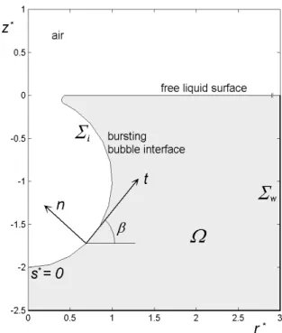
The geometric configuration is axisymmetric. In a meridian plane, rOz, the initial geometric condition for the air/liquid interface Σi corresponds to the bubble gaping cavity joined along the crater line to the free liquid surface [1, 2, and 12], see Figure 1. The bounded axisymmetric liquid domain Ω extends
largely over the bubble size, to obtain a negligible influence of the solid walls Σw (lateral and base surface of a cylindrical pool). The liquid domain boundary is denoted Σ =Σi ∪Σw. We take a unit outward normal n on Σ . The angle β is defined between the radial unit vector and the tangent unit vector t. The curvilinear abscissa s starts from the bottom of the bubble cavity, follows the interface
i
Σ , than the solid surface Σw, and ends on the Oz axis.
Figure 1. Geometric initial configuration
The impulsive character of the collapse process leads to a potential flow assumption. The Laplace equation for the velocity potential φ is:
0
2 =
∇ φ . (1)
The viscous effects are taken into account only by the normal viscous stress at the interface: 2µ
(
∂vn ∂n)
, where µ representsthedynamicviscosityoftheliquid, andvn =∂φ ∂n isthenormalcomponentofthevelocityφ
∇ = v .
We adopt the bubble equivalent radius R0 as length scale (the radius of a sphere with the same volume);
0
R
σ aspressurescale,whereσ isthesurfacetension;
( )
ρσ R0 as velocity scale, and the ratio between
length and velocity as time scale. According to the choice of scales, the Weber number takes always the unit value We=1, the Froude number is
(
2)
0
R g
Fr=σ ρ , and the Reynolds number is
(
ρσ)
12 µ0
R
Re= . Dimensionless variables will be denoted by an asterisk.
The dimensionless Euler’s equation is written:
( )
∗ ∗ ∗ +∇ =−∇ − ∇ ∇ z Fr 1 p 2 v t 2 * * ∂ φ ∂ . (2)The viscous effects are considered through the normal momentum balance at any point of the interface Σi:
( )
0 n Re 2 z p p R 1 R 1 We 1 2 * 2 = − + − + ∗ ∗ ∗ ∗ ∗ ∗ 0 2 1 ∂ φ ∂ , (3)where p∗
( )
z∗ is the dimensionless liquid pressure on the interface at z∗ level, and ∗0
p is the dimen-sionless reference pressure at the free surface level (at z∗ =0).
A non-penetrability condition at the interface Σi is also considered.
Combining equations (2) and (3) to reduce the pressure terms [2, 7], we obtain the Bernoulli’s equation: 2 2 2 n Re 2 Fr z R 1 R 1 We 1 2 v t 1 2 ∗ ∗ ∗ ∗ ∗ ∗ ∗ ∗ − − + + − = ∂ φ ∂ ∂ φ ∂ (4)
The expressions of the normal gradient of normal velocity ∂2φ∗ ∂n∗2 are defined in [1] and [2].
The interface is frozen till the beginning of the cavity collapse, so the initial kinetic conditions correspond to a velocity field equal to zero [1]. 3. NUMERICAL METHOD
The numerical method used in our simulations is detailed in [1, 2] and [7].
The problem is successively divided into tiny variable time steps ∆t∗, defined by a gravity-capillary waves criterion [5]:
( )
2 1 min 3 min 3 s Fr s We 2 t − ∗ ∗ ∗ + ≤ ∆ π ∆ π ∆ , (5) where ∗ min s∆ is the minimum length of a boundary element considered on Σ
( )
t∗ .The temporal interface evolution is determined through a Lagrangian description of a variable number of nodes M=M
(
r∗(t∗),z∗(t∗))
, unevenly redistrib-uted on the boundary Σ( )
t∗ at each time step, with respect to some criteria like the adaptation at surface gradients [4]: that leads to a concentration of nodes at places where the interface curvature is important, or where two portions of the interface approach one another [7]. On each boundary element, cubic splines define the geometric variables, and cubic Hermite polynomials approximate the field variables.We recall the basic computation steps that are per-formed within such a transient free-boundary problem.
c At a fixed instant t∗, we solve the dimensionless form of the Laplace equation (1), to obtain φ∗
( )
t∗ , hence, the corresponding normal component ∗n
v , and tangential component ∗
t
v of the velocity.
d A time-stepping scheme allows the connection of two successive steps to determine the new potential values and interface position at the following instant
(
t∗+ t∆ ∗)
. The time progression is made throughsecond-order limited Taylor series expansions of the functions φ∗
( )
t∗ , r∗( )
t∗ , and z∗( )
t∗ respectively [1, 2, 7].The Boundary Element Method (BEM) is well adapted to the first type of calculation, replacing the Laplace’sequationextendedinthewholeliquiddomain Ω, by a second kind Fredholm integral equation extended only on the boundary Σ . For this direct BEM calculations [3, 4, 13, 14], the velocity field is generated by sources of strength ∗
( )
∗P
n
P ∂
∂φ ,
super-posed to normal doublets (dipoles) of strength
( )
(
−φ∗ P)
, spread over Σ . The integral equation on boundary Σ is written:( )
(
)
(
)
( )
( )
M ; M , 2 n P MP 1 n MP 1 P * P P P P Σ φ π Σ ∂ ∂φ Σ ∂ ∂ φ Σ Σ ∈ = = + + −∫
∫
∗ ∗ ∗ ∗ d d (6)where MP is the dimensionless distance between the observation point M and the singularity point P. We define kinetic conditions of Dirichlet type on the gas-liquid interface Σi, where the velocity potential
∗
φ is known, and of Neumann type on the immobile solid surface Σw, where the normal velocity vanishes:
0
n =
∂ ∂φ∗ ∗ .
By solving the integral equation (6) for the velocity potential φ∗
( )
t∗ at each point M =M(
r∗(t∗),z∗(t∗))
, we obtain the normal component v∗ =∂ ∗ ∂n∗n φ , and
tangential component v∗ =∂ ∗ ∂s∗
t φ of the velocity
at each point M∈Σ . Thus, we define the velocity field v∗
( )
t∗ on the whole surface Σ . Then, this velocity distribution can be extended by subsequent computation to the adjacent liquid, in order to obtain the velocity field within the whole liquid domain Ω.An overview of boundary integral formulations is presented in [3] and [4], where it is shown that within the BEM formulation, the velocity field and the potential field can be expressed in terms of either a distribution of dipoles over the interface, either a distribution of vortices - a sheet vortex [11] over the interface, due to the equivalence between the dipole
and the vortex representation. So, an equivalent BEM formulation can be obtained by the integral representation of the velocity field v∗
( )
t∗ in terms of a vortex distribution. That formulation involves the integral equation for the vortex strengthΣ ∗ ∗
∗ =−n ×v
γ , and the Bernoulli’s equation for ∗
∗ ∂
∂γ t . From the vortex strength γ∗
( )
t∗ computed at each point M∈Σ , we could obtain the scalar velocity potential φ∗( )
t∗ . We highlight that a potential flow is imposed to the liquid, so that the vorticity is confined only at the air-liquid interface, and it cannot diffuse outside the interface [3, 4, and 15].The second-order limited Taylor series expansion of the velocity potential φ∗
( )
t∗ is written:(
) ( )
, t O ! 2 t t t t t t t 3 t t + + + + = + ∗ ∗ ∗ ∗ ∗ ∗ ∗ ∗ ∗ ∗ ∗ ∗ ∗ ∗ ∆ ∆ φ ∆ φ φ ∆ φ 2 2 2 D D D D (7)where the material derivative of the velocity potential is Dφ∗ Dt∗ =∂φ∗ ∂t∗+
( )
∇φ∗ 2, where the local time derivative ∂φ∗ ∂t ∗ is defined by Bernoulli’s equation (4). The corresponding second-order Lagrangian derivative, D2φ∗ Dt∗2 , is defined in [1, 2, 7]. Its expression includes the radial component of the velocity vr∗ =(
−vn∗sinβ+vt∗cosβ)
, together with the axial-one vz∗ =(
vn∗cosβ+vt∗sinβ)
. The expression of2 D
D2φ∗ t∗ , includes also some derivatives, namely 2
D
D2r∗ t∗ , D2z∗ Dt∗2 , and D
(
∂2φ∗ ∂n∗2)
Dt∗ , all of them having slightly complicated expressions (for example, outside the Oz axis, the last derivative includes 20 terms, obtained by using the Maple soft-ware for symbolic computation [1, 2]). All those de-rivatives need the normal and tangential dede-rivatives of ∂φ∗ ∂t ∗, obtained upon the computation of an extra Laplace equation, ∇2(
∂φ∗ ∂ t∗)
=0, withboundary conditions ∂φ∗ ∂t ∗from (4) on i Σ , and
(
∂ ∂t)
∂n =0 ∂ φ∗ ∗ ∗ on w Σ .The numerical code precision is evaluated through the global mechanical energy balance [2, 5]:
∫
∫
∫
∫
∗ ∗ ∗ ∗ ∗ ∗ ∗ ∗ ∗ ∗ ∗ ∗ ∗ ∗ − = = + + + Σ Σ Σ Σ ∂ φ ∂ ∂ ∂φ ∂ ∂φ φ , A n n Re 2 A z Fr 2 1 t A We 1 A n 2 1 t 2 2 d d d d d d d d 2 i i (8)where dA∗ is the axisymmetric boundary element. Upon azimuthally integration, the mechanical energy balance deals with line integrals of the terms com-puted through the BEM, being easily implemented in the computational procedure. The dissipation of mechanical energy due to shear viscosity depends only on the normal component of the velocity, and on its normal derivative, ∂2φ∗ ∂n∗2 .
4. NUMERICAL RESULTS
Within this paper, our simulations point on local vortex formation that leads to the parent bubble interface pinching-off. We focus on the interface rupture, which appears at the bottom of the cavity, near the area that encircles the inferior part of the upward liquid jet that starts to form. Following the rupture, a tiny toroidal air bubble detaches, being entrained downwards within the surrounding liquid, while the liquid jet continues its highly-speed upward movement. Near the interface rupture area, the velocity field within the liquid is typical for a vortex.
We exemplify this kind of computation for a parent air bubble of equivalent radius R0 =0.5 mm, which
bursts at the free surface of distilled water. The dimensionless numbers are: We=1; Fr=29.71, and
1 . 190
Re= , corresponding to physical liquid properties at 20ºC.
Starting with geometric and kinetic conditions de-scribed in section 2, the early collapse behaviour can bedescribedbyavelocitydistributionontheparent bubblegapingcavityliketheonepresentedinFigure2.
Figure 2. Velocity distribution on the interface at the beginning of the bubble collapse
As described in section 3, in Figure 2 there is a concentration of nodes at places where the interface
curvature is important, for example around the crater border, while nodes are rare on the spherical part corresponding to the bottom of the bubble cavity. As we will see further (see Figures 5-8), a concentration of nodes is also used at places where two portions of the interface approach one another, for example around the interface pinching-off line.
In Figure 2, it can be seen that the crater tends to be enlarged (due to strong surface tension forces), the nodes spread over the crater area being submitted to velocity vectors, having radial components of great value, which point in opposite direction with respect to the axis if symmetry. The nodes placed on the inferior part of the cavity tend to move towards the centre of the parent bubble.
Figure 3. Interface evolution at the beginning of the collapse of a parent bubble of 0.5 mm equivalent
radius, for an air/ distilled water couple
Figure 4. Beginning of the liquid jet formation
Following the velocity distribution presented in Figure 2, the collapse process continues with
sequences of the parent bubble interface evolution like the ones presented in Figure 3: the bottom of the bubble cavity rises, while the crater border is continuously enlarged.
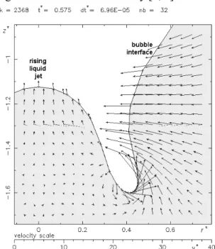
The jet formation starts as in Figure 4, then it continues to rise slowly like in Figures 5 and 6. When the liquid jet forms, there are strong changes in interface curvature at the inferior part of the parent bubble cavity. In Figures 5 and 6, it can be seen that the lateral part of the cavity is submitted to an increasing velocity distribution, associated to strong curvature gradient. It has been shown that the density jump and the strong gradient of curvature are at the origin of creation of the vorticity [3, 4].
Figure 5. Early stage of the local vortex formation
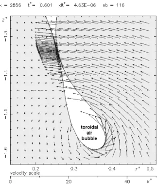
Figure 7. Interface rupture and entrapped toroidal air bubble
Thus, near the cavity interface, within the sur-rounding liquid, a local vortex forms, turning towards the Oz axis with strong velocity values on the right side of the interface.
Finally, the velocity distribution characterising the local vortex leads to the interface pinching-off as in Figure 7. Following the rupture, a tiny toroidal air bubble is entrapped within the liquid, being entrained downwards by the subsequent liquid flow. After that, the liquid jet continues to rise with increasing speed. WepresentinFigure8azoomedimageoftheinterface
at the rupture moment. The velocity vectors are typical to a local vortex, enclosing the toroidal bubble.
The mechanical energy balance (8) expressed in percents as ratio between the energy variation and the initial mechanical energy is plotted versus the dimensionless time, during the whole collapse evolution, till the interface pinching-off (see Figure 9). It was shown [2] that a value of few percents is acceptable for this kind of highly transient free-surface problem
Figure 8. Vortex around the toroidal bubble at the interface rupture moment
Figure 9. Interface pinching-off (left side) and mechanical energy balance during the whole cavity evolution, from the initial moment till the interface rupture (right side)
Finally we present computations [2] that avoid any interface pinching-off at the beginning of the jet formation, by using an appropriate time step criterion (5). The interface evolution associated to the collapse process, from the initial moment till the first jet drop ejection, is presented in Figure 10 for an air bubble of equivalent radius R0 =2 mm, which bursts at the
free surface of distilled water.
−3 −2 −1 0 1 2 3 −2.5 −2 −1.5 −1 −0.5 0 0.5 1 1.5 2 2.5
R0 = 2 mm; Fr = 1.857; Re = 380.3; air/ distilled water
r *
z
*
bottom of the bubble interface rising liquid jet
jet drop prior to ejection
air
liquid
Figure 10. Interface evolution associated to the collapse process of a parent bubble of 2 mm equivalent radius, for an air/ distilled water couple
Thedimensionlessnumbersare:We=1;Fr=1.857, and Re=380.3. In figure 11 we present the zoomed image of the jet formation, where the changes in interface curvature are well described. Within this last computation, an optimal variable time step is selected in order to avoid crossing-over of the nodes during the displacement of the interface. The time step selection obeys some extra requirements described in [1] and [2]. −1.5 −1 −0.5 0 0.5 1 1.5 −2 −1.5 −1 −0.5 0 0.5
R0 = 2 mm; Fr = 1.857; Re = 380.3; air/ distilled water
r *
z
*
Figure 11. Zoomed image of the jet formation
5. CONCLUSIONS
The numerical simulation of an air bubble bursting at a free surface was made in a potential flow of a viscous fluid assumption, through the Boundary Element Method (BEM). Within the BEM formula-tion, the velocity field and the potential field can be expressed in terms of either a distribution of dipoles, either a distribution of vortices over the interface. A potential flow is imposed to the liquid, so that the vorticity is confined only at the air-liquid interface, and it cannot diffuse outside the interface.
We found vortex configurations attached to some specific regions of the interface, where high velocities appear at points of strong curvature. Those vortex configurations may produce the interface rupture andairentrainmentduringtheparent-bubblecollapsing process. In this paper, we point on the parent bubble interface pinching-off, which leads to the formation of a tiny toroidal air bubble. Once the velocity field is obtained through BEM over the whole interface, it can be extended by subsequent computation to the adjacent liquid, in order to obtain the velocity field.
Itisshownthatcomputationsthatavoidanyinterface pinching-off at the beginning of the jet formation can be performed by using an appropriate time step criterion.
REFERENCES
1. GeorgescuS.-C.(1999)Evolutiond’unebulle:Formation à partir d’un orifice et éclatement à la traversée d’une surfacelibre,Ph.D.thesis,InstitutNationalPolytechnique de Grenoble, France
2. Georgescu S.-C., Achard J.-L., Canot É. (2002) Jet drops ejection in bursting gas bubble processes, European Journal of Mechanics, B/Fluids, vol 21, pp 265-280 3. Canot É. (1989) Généralisation de la méthode intégrale
aux frontieres pour les systèmes fluide-fluide, Ph.D. thesis, Institut National Polytechnique de Grenoble, France
4. Canot É., Achard J.-L. (1991) An overview of boundary integral formulations for potential flows in fluid-fluid systems, Arch. Mech., Warszawa, vol 43, no.4, pp 453-498
5. Canot É. (1999) Stability criteria for capillary/ gravity free-surface waves in BEM simulations of viscous potential flows, In: Aliabadi M. H. (ed) Proc. of the Int. Conf. on Boundary Element Techniques, London, U.K, pp 395-404
6. Georgescu S.-C., Achard J.-L., Canot É. (1998) Bubble cavity collapse and liquid jet formation simulation in bursting gas bubble process, In: Book of Abstracts, EURO-MECH Colloquium 376/ Waves in Two-Phase Flows, Istanbul, Turkey, pp 27-30
1. Canot É., Georgescu S.-C., Achard J.-L. (2001) Bursting air bubble at a free surface: Regridding influences on the interface evolution, In: Anton I., Ancuşa V., Resiga R. (eds) Numerical Simulation for Fluid Mechanics and Magnetic Liquids, Editura Orizonturi Universitare, Timişoara, pp 123-132
8. Canot É., Georgescu S.-C., Vincent S. (2004) Test-case No 21: Gas bubble bursting at a free surface, with jet formation (PN-PE), Multiphase Science and Technology, vol 16, nos 1-3, pp 121-126
9. Joseph D. D., Liao T. Y., Hu H. H. (1993) Drag and moment in viscous potential flow, Eur. J. Mech., B / Fluids, vol 12, no. 1, pp 97-106
10. Canot É, Georgescu S.-C. (1997) Bilan d’énergie mécanique pour le suivi d’interface: Modèle potentiel avec prise en compte des contraintes visqueuses normales. In: Actes du 13ème Congrès Français de Mécanique, Poitiers-Futuroscope, France, vol 3, pp 23-26
11. Batchelor G. K. (1994) An Introduction to Fluid Dynamics, 16th edition, Cambridge University Press, Cambridge, New York, Oakleigh Australia, 615 p
12. Georgescu S.-C., Achard J.-L., Canot É. (1997) Large bubble entrapped beneath a free liquid surface, In: Proc. of the VI-th Symp. Techn., Installations and Equipments for Improving the Environmental Quality, Bucharest, vol 1, pp 268-275
13. Machane R. (1997) Contributions de la Méthode Intégrale aux Frontières au suivi d’interfaces, Ph.D. thesis, Université Joseph Fourier, Grenoble, France 14. Machane R., Canot É. (1997) High-order schemes in
Boundary Element Methods for transient non-linear free surface problems, Int. J. Numer. Methods Fluids, vol 24, pp 1049-1072
15. Longuet-Higgins M. (1998) Vorticity and curvature at the free surface, J. Fluid Mech., vol 356, pp 149-153