DÉPARTEMENT DES SCIENCES APPLIQUÉES
Durable nanostructured superhydrophobic coatings
on aluminum alloy substrates
Master Candidate: Jiawei Xiong
Permanent Code: XIOJ18119100
Director: Prof. D. K. Sarkar
ABSTRACT
Superhydrophobic thin films based on metal substrates has attracted great attention due to a wide range of applications in the industry including anti-corrosion, anti-icing and self-cleaning surfaces. Recently, numerous methods have been reported to prepare superhydrophobic thin films but most of them will be destroyed or degrade quickly when applied outdoor or in harsh environments. Therefore, it is extremely important to develop durable superhydrophobic thin films, especially considering the properties of corrosion resistance, Ultra-Violet (UV) durability and mechanical durability.
In this project, superhydrophobic cobalt stearate thin films with excellent anti-corrosion properties were successfully fabricated on aluminum substrates via a simple, electrodeposition process. The correlation between the surface morphology, composition as well as wetting properties and the molar ratio of inorganic cobalt salt/organic stearic acid in the electrolyte were studied carefully. The optimum superhydrophobic surface formed on the cathodic aluminum substrate was found to have a maximum contact angle of 161o and the largest polarization resistance of 1591 kΩ cm2, indicating an excellent barrier against chemical corrosion. Electrical equivalent
circuits have been suggested to better understand the corrosion principals on the interface based on the data from the corresponding electrochemical impedance spectroscopy (EIS).
superhydrophobic cobalt stearate thin films as mentioned above were found to be UV durable as the roll-off properties sustain in the period of two months’ accelerated UV degradation test. Furthermore, inspired from this finding, another novel superhydrophobic nanocomposite thin films have been successfully fabricated on aluminum substrates by embedding cobalt stearate (CoSA)-covered TiO2 nanoparticles
in a hydrophobic polymethyl-hydrosiloxane (PMHS) matrix (PMHS/TiO2@CoSA)
utilizing the sol-gel process. Compared to sharp decreases of water contact angle on the superhydrophobic PMHS/TiO2 thin films (without CoSA), the PMHS/TiO2@CoSA
superhydrophobic thin films exhibited a nearly constant water contact angle of 160o under continuous UV irradiation for more than one month. The designed scheme of TiO2@CoSA core-shell structure not only increases the hydrophobic properties TiO2
nanoparticles surface, but also confined the photocatalytic efficiency of TiO2
nanoparticles. A plausible model has been suggested to explain the UV durable mechanism.
In addition, to improve the adhesion strength of superhydrophobic nanocomposite PMHS/TiO2@CoSA thin films, the thin self-assembled monolayers
(SAM) of GPTS were deposited on the surface of aluminum substrates. The presence of SAM was confirmed by ATR-FTIR, EDX as well as EIS studies. The adhesion strength was expected to be improved by the formation of chemical bondings due to the presence of SAM. But both of the results were found to be 2B between the substrates of as-received aluminum and SAM modified aluminum following the (ASTM) D
3359-by comparing the surfaces on as-received aluminum and SAM modified aluminum substrates after the removal of adhesive tape.
It is believed that this project will contribute to a better understanding of superhydrophobic phenomena as well as realizing the application of superhydrophobic surfaces in the industrial world.
RÉSUMÉ
Les couches minces superhydrophobes déposées sur des substrats métalliques ont suscité beaucoup d’attention vu leurs nombreuses applications industrielles comme les revêtements anticorrosifs et antigivrants ainsi que les surfaces autonettoyantes. Ces derniers temps, de nombreuses méthodes d’élaboration de couches minces ont été proposées. Cependant, la plupart des couches obtenues se détruisent ou se dégradent assez rapidement lorsqu’elles sont utilisées à l’extérieur ou exposées à des conditions sévères. Par conséquent, il est très important de développer des couches minces superhydrophobes résistantes ayant de bonnes propriétés anticorrosion et anti ultraviolet ainsi qu’une bonne résistance mécanique.
Dans ce projet, des couches minces superhydrophobes de stéarate de cobalt, ayant de très bonnes propriétés anticorrosion, ont été élaborées avec succès par électrodéposition sur un substrat d’aluminium. Ensuite, les corrélations entre les propriétés de la surface (morphologie, composition et mouillabilité) et le rapport molaire sel de cobalt inorganique/acide stéarique organique dans l’électrolyte ont été étudiées minutieusement. Il a été observé que la surface superhydrophobe optimale, formée sur un substrat d’aluminium cathodique, possède l’angle de contact maximal de 161° et la résistance de polarisation la plus élevée de 1591kΩ cm2, offrant ainsi une excellente barrière contre la corrosion. Afin de mieux comprendre les principes de la corrosion à l’interface, un circuit électrique équivalent a été proposé en se basant sur
stéarate de cobalt possède une bonne résistance aux rayonnements ultraviolets (UV). En effet, après un test de dégradation accélérée par UV de deux mois, les propriétés hydrophobes des couches minces ne se sont pas altérées. En se basant sur ces résultats, d’autres couches minces innovantes, faites à partir dépôts nanocomposites superhydrophobes, ont été fabriquées avec succès sur des substrats d’aluminium. Pour cela, des nanoparticules de TiO2 revêtues de stéarate de cobalt (CoSA) ont été
incorporées dans une matrice de polyméthyle-hydrosiloxane (PMHS) superhydrophobe (PMHS/TiO2@CoSA) en utilisant le procédé sol-gel. Alors que les couches minces
superhydrophobes de PMHS/TiO2 (sans CoSA) montrent une diminution rapide de
l’angle de contact avec l’eau après irradiation continue par rayonnement UV pendant plus d’un mois, les couches de PMHS/TiO2@CoSA conservent un angle quasi-constant
de 160°. La structure en noyau-enveloppe de TiO2@CoSA permet non seulement
d’augmenter les propriétés hydrophobiques de la surface des nanoparticules TiO2, mais
aussi de limiter leur activité photocatalytique. Un modèle plausible a été proposé pour expliquer les mécanismes de résistance aux UV.
En outre, afin d’améliorer l’adhérence des couches minces nanocomposites
superhydrophobes PMHS/TiO2@CoSA, des monocouches auto-assemblées (SAM) de
GPTS ont été déposées sur des substrats d’aluminium. La présence des SAM a ensuite été confirmée par des analyses ATR-FTIR, EDX ainsi que EIS. Il a été espéré que les SAM améliorent l’adhérence au substrat par la formation de liaisons chimiques. Cependant, Les tests sur des substrats non-traités et des substrats traités par SAM montrent, dans les deux cas, une adhérence de type 2B selon la norme ASTM D
3359-02. Néanmoins, une légère amélioration peut être observée en comparant les surfaces non traitées à celle traitées par SAM après l’enlèvement du ruban adhésif.
Ce projet contribuera à une meilleure compréhension des phénomènes superhydrophobiques ainsi qu’à la réalisation des applications des surfaces superhydrophobes dans le monde industriel
ACKNOWLEDGEMENTS
This project was financially supported by Natural Science and Engineering Research Council of Canada (NSERC), Université du Québec à Chicoutimi (UQAC) and Aluminum Research Centre (REGAL). I would like to thank these organizations for their continuous support for my research.
Foremost, I would like to express my sincere and special gratitude to my director, Prof. Dilip Sarkar, for his patience, guidance, encouragement and continuous support of my research. He always has a positive attitude towards any trouble and endless smart ideas to solve them efficiently. Furthermore, he keeps putting forward hard questions which incented me to widen my research from various perspectives. It is really my honor to work with him and learn from his expertise throughout my master studies.
I am extremely grateful to my co-director Prof. X.-Grant Chen, for his careful technical discussions and encouragement all the time. I sincerely appreciated that he gave me the valuable opportunity to studying in UQAC.
My sincere thanks also goes to all my colleagues, professors and technicians in CURAL. Without their precious support and favor, it would not be possible to complete this research successfully. Those includes Dr. Zhan Zhang, Dr. Saleema Noormohammed, Dr. Kun Liu, Dr. Ying Huang, Dr. Jean-Denis Brassard, Dr. Xianai Huang, Dr. Jian Qin, Dr. Lei Pan, Dany Racine, Émélie Brideau, Alexandre, Ying Lu, Zhen Li, Lanfeng Jin, Hezhaoye Ma, Qinfu Zhao, Na Xu and Wei Xu.
Mohan for their comments on my manuscripts and reports. I have learnt a lot from their native English expressions, too. Moreover, I sincerely appreciate Dr. Abderrahmane Benzaoui for his kind help in the French translation of the abstract for my thesis.
Last but not the least, Yafei Li, my beloved girl-friend, had been studying in KU Leuven University in Belgium in the past two years. It is not so easy to run a continuous relationship for 4 years, especially for such a long-distance relationship. I am sincerely sorry for not able being aside and accompanying with you these years. I am extremely grateful for your understanding, support, encouragement and love all the time. I love you, darling! I must convey the deepest gratitude and love to my dear parents, for their endless support, love, understanding, guidance and patience in all my life. Mom and Dad, I love you!
THESIS CONTENTS
ABSTRACT ... 1 RÉSUMÉ ... 4 ACKNOWLEDGEMENTS ... 7 THESIS CONTENTS ... 9 FIGURE CONTENTS ... 12 TABLE CONTENTS ... 18 EQUATION CONTENTS ... 19 1. Introduction ... 20 1.1 Introduction ... 20 1.2 Definition of problem ... 23 1.3 Objectives ... 24 1.4 Methodology ... 25 Reference ... 25 2. Literature review ... 282.1 Fabrication of superhydrophobic coatings ... 28
2.1.1 Sol-gel process ... 28
2.1.2 Electrochemical deposition ... 29
2.2 Self-assembled monolayers (SAM) ... 30
2.2.1 Preparation of SAM ... 31
2.2.2 Characterization and analysis of SAM ... 33
2.2.3 Important factors about SAM ... 34
2.3 Durable superhydrophobic coatings ... 35
2.3.1 Mechanical durability ... 36
2.3.2 UV durability ... 46
2.3.3 Thermal durability ... 56
2.3.4 Chemical durability ... 59
3. Experimental ... 69
3.1 Materials ... 69
3.2 Sample preparation ... 69
3.2.1 Fabrication of superhydrophobic cobalt stearate thin films by electrodeposition ... 69
3.2.2 Fabrication of superhydrophobic films incorporating TiO2 nanoparticles by sol-gel process ... 70
3.2.3 SAM modified aluminum substrates for improved adhesion properties ... 72
3.3 Characterization: Wettability, Topography, Morphology and Structure, Chemical composition, Corrosion behavior analysis and UV degradation behavior analysis ... 73
4. Corrosion resistant superhydrophobic cobalt stearate thin films coated aluminum alloys by electrodeposition ... 80
4.1 Introduction ... 80
4.2 Experimental ... 84
4.3 Results and discussion ... 86
4.3.1 Surface morphology and wetting ... 86
4.3.2 Surface composition... 90
4.3.3 Surface wettability ... 99
4.3.4. Mechanism ... 103
4.3.5 Corrosion resistance properties ... 107
4.4 Summary ... 123
Reference ... 124
5. Ultra-Violet durable superhydrophobic thin films coated aluminum alloys ... 128
5.1 UV durable superhydrophobic cobalt stearate thin films prepared by one-step electrodeposition ... 128
5.1.4 Summary ... 134
5.2 UV durable PMHS/TiO2@CoSA superhydrophobic coatings by sol-gel/spin-coating process ... 135
5.2.1 Introduction ... 135
5.2.2 Experimental ... 138
5.2.3 Results and discussions ... 139
5.2.4 Summary ... 150
Reference ... 150
6. Superhydrophobic thin films applied on SAM modified aluminum substrates ... 154
6.1 Electrochemical impedance spectroscopy (EIS) studies of self-assembled monolayers (SAM) on aluminum substrates... 154
6.1.1 Introduction ... 154
6.1.2 Experimental ... 156
6.1.3 Results and discussion ... 157
6.1.4 Summary ... 163
6.2 Mechanical durability test of superhydrophobic coatings on SAM modified aluminum substrates... 164
Reference ... 166
7. Conclusions ... 169
8. Recommendations ... 172
FIGURE CONTENTS
Figure 1. 1 The water drop in equilibrium state on a solid surface [2] ... 20 Figure 1. 2 Superhydrophobic phenomena in nature [4, 5, 8] ... 21
Figure 2. 1 The scheme for different bonding modes of SAM with APTES [12] 30 Figure 2. 2 Two methods of making a SAM [13] ... 32 Figure 2. 3 Cross-hatch tape adhesion test for coatings with 10–20 nm silica fillers. (a-c) Hydrophobic surface and (d) superhydrophobic surface [31] ... 39 Figure 2. 4 Images of the grid area of a sample before (a) and after (b) Cross-hatch tape adhesion test [32] ... 39 Figure 2. 5 Schematic illustration of adhesion strength test [33] ... 40 Figure 2. 6 Schematic diagram of the abrasion test equipment with sand paper used as an abrasive surface [34] ... 41 Figure 2. 7 (a) Contact angle and sliding angle on the coating as a function of abrasion length; SEM images for the coating after abrasion length of (b) 400mm ... 42 Figure 2. 8 Contact angle and sliding angle on the metal/polymer composite surface as a function of abrasion cycles [35] ... 43 Figure 2. 9 Contact angle and sliding angle on PTFE/PVDF composite surfaces as a function of abrasion cycles [36] ... 44 Figure 2. 10 Image for pencil hardness test ... 45 Figure 2. 11 Solar radiation spectrum ... 47 Figure 2. 12 Photographs of water droplet shape on TiO2 coatings before (left) and
after (right) UV illumination for 6h [42] ... 48 Figure 2. 13 Reversible super-hydrophobic-super-hydrophilic transition of the
as-prepared films under the alternation of UV irradiation and dark storage [43] ... 50
Figure 2. 15 Changes of WCAs of the superhydrophobic coatings with different
TiO2 contents under QUV accelerated weathering test [45] ... 52
Figure 2. 16 Evolution of water CA on OTS-modified ZnO NW array (squares) and OTS-modified ZnO@SiO2 NW array (triangles) under UV irradiation[49] . 53 Figure 2. 17 Photo degradation process of PTES based superhydrophobic surface [47] ... 54
Figure 2. 18 Contact angles of three different layers of SiO2 on the top of TiO2 (P25)*3 coated superhydrophobic samples after certain periods of time [47] ... 55
Figure 2. 19 Contact angle as a function of temperature for organically silica coatings (black) before (blue) after modified by TMCS [53] ... 57
Figure 2. 20 (a) Water contact angle plotted against the thermal treatment temperature; (b) the SEM images of FPI and PS samples before and after heating at 150 oC [56] ... 58
Figure 2. 21 Model for the anticorrosion mechanism[57] ... 60
Figure 2. 22 (a) Potentiodynamic polarization curves, (b) Nyquist plots and (c) Bode plots of the bare Al alloy substrate and the as-prepared superhydrophobic surface measured in 3.5 w.t.% NaCl solution [63] ... 62
Figure 2. 23 Typical electrical equivalent circuits used for superhydrophobic surfaces [64] ... 63
Figure 3. 1 The schematic model for preparation of cobalt stearate (CoSA) by electrodeposition ... 70
Figure 3. 2 Photograph of Single Wafer Spin Processor ... 71
Figure 3. 3 The Schematic diagram of a self-assembled monolayer of GPTS ... 72
Figure 3. 4 Photograph of contact angle goniometer ... 74
Figure 3. 5 Photograph of 3D surface optical profilometer ... 74
Figure 3. 6 Photograph of scanning electron microscope ... 75
Figure 3. 7 Photograph of image analysis system... 76
Figure 3. 9 Photograph of X-ray diffraction system ... 77
Figure 3. 10 Photograph of corrosion test ... 78
Figure 3. 11 Photograph of UV degradation test ... 78
Figure 3. 12 Photograph of UV-Vis spectroscopy ... 79
Figure 4. 1 SEM images (left column) of (a) as-received aluminum substrate and electrodeposited cathodic aluminum substrates with the application of 10V DC voltage for 10 min in the Co (II)/SA ethanolic solution with molar ratios of (c) 0, (e) 0.02, (g) 0.08, (i) 0.2, (k) 0.5 and (m) ∞. The insets show the images of water drops on respective surfaces. The molar ratio ∞ represents a pure solution of Co(II) ions in ethanolic solution having concentration of 0.01 M. The SEM images (right column) in high magnification (b), (d), (f), (h), (j), (l), (n) correspond to those at lower magnification in the left column ... 87
Figure 4. 2 EDS spectra of different areas on the aluminum substrate modified by electrodeposition in the mixed ethanolic solution with a Co/SA molar ratio of 0.5: (a) area 1: the gray honeycomb-like framework, (b) area 2: the white clusters ... 91
Figure 4. 3 (a) low angle XRD patterns of (I) As-received aluminum, (II) 0.08/Al for 10min, (III) 0.08/Al for 60min, and (IV) Cobalt stearate drop films on aluminum substrates; (b) shows the corresponding high angle XRD patterns of (a) ... 93
Figure 4. 4 (a) shows FTIR spectra of (I) as-received aluminum substrate and (III) solid stearic acid, as well as chemically modified aluminum substrates by electrodeposition in ethanolic solution with a Co/SA molar ratio of (II) 0, (IV) 0.08, (V) 0.2, (VI) 0.5; (b) compares the FTIR spectra of chemically modified aluminum substrates by electrodeposition in ethanolic solution with a Co/SA molar ratio of (I) ∞, (III) 0.5 and (II) aluminum substrates dropcoated with pure cobalt stearate ... 95
molar ratio of Co/SA in the electrolytes; The curve (c) depicts the calculation results of (a)/(b) by peak area ... 97 Figure 4. 6 (a) Surface roughness (b) and water contact angle as well as contact angle hysteresis of as-received aluminum substrate and electrochemically modified cathodic aluminum substrates with the application of 10V DC voltage for 10 min in varied molar ratios of Co/SA ethanolic solution ... 99 Figure 4. 7 (a) Potentiodynamic polarization curves; (b) Polarization resistance; (c) Corrosion current density of as-received aluminum, and thin films prepared from a cobalt nitrite and stearic acid mixed solution with Co/SA molar ratios of 0.08, 0.2, 0.5 as well as electrodeposited films in a pure solution of stearic acid (i.e. Co/SA=0) and cobalt nitrite (i.e. Co/SA=∞), respectively ... 108 Figure 4. 8 (a) The current-potential (I-E) curves obtained from the potential variation of ± 15 mV around the corresponding corrosion potential (Ecorr) for
the Rp calculated by ohm’s law; (b) the Rp value calculated by ohm’s law (Rp1)
versus by Stern-Geary equation (Rp2) ... 113
Figure 4. 9 (a) The corrosion potentials (Ecorr, black) and open circuit potentials
(OCP, blue) for thin films samples Potentiodynamic polarization curves of (1) as-received aluminum, and thin films prepared from a cobalt nitrite and stearic acid mixed solution with Co/SA molar ratios of (3) 0.08, (4) 0.2, (5) 0.5 as well as electrodeposited films in a pure solution of (2) stearic acid and (6) cobalt nitrite, respectively. A horizontal dotted line has been plotted at -700 mV to guide the eyes. (b) Ecorr obtained from Stern-Geary equation versus OCP
stabilized in 3.5 w.t.% sodium chloride solution for 24h ... 114 Figure 4. 10 (a)Nyquist plots (b) Bode modulus diagrams and (c) Bode phase angle diagrams of superhydrophobic thin films electrodeposited on Al from Co/SA molar ratio of 0.2 and as-received aluminum substrate. (d) Electrical equivalent circuits employed to simulate the EIS study of (d1) as-received aluminum and (d2) superhydrophobic thin films electrodeposited on Al from Co/SA molar ratio of 0.2. The inset image shows the amplified diagram in the higher frequency range ... 117
Figure 5. 1 Water contact angle (black square) and contact angle hysteresis (blue dot) on the surface of the electrodeposited cobalt stearate film as a function of UV irradiation time ... 131 Figure 5. 2 SEM images of electrodeposited cobalt stearate film (a) before and (b) after UV degradation for 60 days. The insets show the water drop on the corresponding surfaces... 133 Figure 5. 3 ATR-FTIR spectra of (a) stearic acid powder; the electrodeposited cobalt stearate film (b) before and (c) after UV degradation for 60 days .... 134 Figure 5. 4 (a) Low angle XRD patterns of (I) stearic acid powder and (II) cobalt stearate films on aluminum substrates; (b) ATR-FTIR spectra of (I) stearic acid powder and (II) cobalt stearate drop films on aluminum substrates. The inset figure in (a) shows the corresponding UV-Vis absorption spectrum of cobalt stearate ... 140 Figure 5. 5 (a) The variation of water contact angle on PMHS/TiO2 and
PMHS/TiO2@CoSA superhydrophobic thin films as a function of UV
irradiation time. The inset images in (a) show the water drop on the corresponding surfaces respectively; (b) ATR-FTIR spectra of (I) PMHS liquid and (II) PMHS/TiO2@CoSA superhydrophobic thin films. The inset figure in
(b) shows the amplificative ATR-FTIR spectra in the range from 3050 cm-1 to
2750 cm-1; (c) XRD patterns of (I) aluminum substrates (II) PMHS/TiO2 and
(III) PMHS/TiO2@CoSA; (d) EDS spectra of (d-I) PMHS/TiO2@CoSA and
(d-II) PMHS/TiO2 ... 143
Figure 5. 6 (a) SEM image and (b) The schematic model for the PMHS/TiO2@CoSA coatings on aluminum substrate. The inset image in (a)
shows water drops on this superhydrophobic surface... 147
substrate (SAM/Al) and (c) Al substrate ... 157 Figure 6. 2 SEM images of (a) Al and (c) SAM/Al substrate; EDX spectra of (b) Al and (d) SAM/Al substrate ... 159 Figure 6. 3 (a-c) Nyquist plots for Al and SAM/Al substrates after immersion time in 10-4M NaOH aqueous solution of 2, 4, 6, 8, 10h respectively; (d) Charge transfer resistance (Rct) of Al and SAM/Al substrates as functions of
immersion time; (e) Electrical equivalent circuit model used for fitting of EIS dates of Al and SAM/Al substrates; (f) The variation of open circuit potential (OCP) with immersion time for Al and SAM/Al substrates ... 161 Figure 6. 4 Potentiodynamic polarization curves of Al and SAM/Al substrates after 10 h immersion time in 10-4 M NaOH aqueous solution ... 162 Figure 6. 5 Optical photographs of superhydrophobic PMHS/TiO2 coatings on
as-received aluminum substrates (a) before and (b) after adhesive tape tests; on SAM modified aluminum substrates (c) before and (d) after adhesive tape tests ... 164
TABLE CONTENTS
Table 2. 1 Some important factors of SAMs [12, 14-19] ... 34 Table 2. 2 Classification of test results ... 37
Table 4. 1 The EDS results of atomic element percentages for different areas on the aluminum substrate modified by electrodeposition in the mixed ethanolic solution with a Co/SA molar ratio of 0.5 ... 92 Table 4. 2 The open circuit potential (OCP), corrosion potential (Ecorr), current
density (Icorr) and polarization resistance (Rp) for aluminum substrates
electrodeposited in the solution of varied molar ratio of Co/SA ... 110 Table 4. 3 Electrochemical parameters obtained from electrical equivalent circuits (EEC), fitted EIS data of as-received aluminum and superhydrophobic thin films on Al substrates in 3.5 w.t. % NaCl solution ... 118
Table 6. 1 Results of EIS and potentiodynamic polarization of Al and SAM/Al substrates after the immersion time of 10 hrs in 10-4 M NaOH solution ... 163
EQUATION CONTENTS
cos θ =𝛾𝑆𝑉− 𝛾𝑆𝐿 𝛾𝐿𝑉 (1.1) ... 20 cos𝜃𝑤 = 𝑟 𝑐𝑜𝑠𝜃1 (1.2) ... 22 cos𝜃𝑐 = 𝑓1(𝑐𝑜𝑠𝜃1+ 1) − 1 (1.3) ... 22 𝑍𝐶𝑃𝐸 = 𝑌 1 0(𝑗𝜔)𝑛 (2.1) ... 63 Z = 𝑍𝑟𝑒𝑎𝑙 + j 𝑍𝑖𝑚𝑎𝑔𝑖𝑛𝑎𝑟𝑦 (4.1) ... 86 Z = 𝑍′+ j 𝑍′′ (4.2) ... 86 |Z| = √𝑍′2+ 𝑍′′2 (4.3) ... 86 φ = arctan (|𝑍𝑖𝑚𝑎𝑔𝑖𝑛𝑎𝑟𝑦| 𝑍𝑟𝑒𝑎𝑙 ) (4.4) ... 86 cos𝜃𝑤 = 𝑟 𝑐𝑜𝑠𝜃1 (4.5) ... 101 cos𝜃𝑐 = 𝑓1(𝑐𝑜𝑠𝜃1+ 1) − 1 (4.6) ... 102Co2+ + 2CH3(CH2)16COOH → Co[CH3(CH2)16COO]2 + 2H+ (4.7.1) ... 104
2H+ + 2e− → H2 (4.7.2) ... 104 Co2+ + 2H2O → Co(OH)2 + 2H+ (4.8.1) ... 104 Co(OH)2 → CoOx +H2O (4.8.2) ... 104 2H+ + 2e− → H 2 (4.8.3) ... 104 Rp =2.3I βaβc corr(βa+βc) (4.9) ... 109 R𝑝 =∆𝐸∆𝐼 (4.10) ... 113 𝑍𝐶𝑃𝐸 = 𝑌 1 0(𝑗𝜔)𝑛 (4.11) ... 121 η = 𝑅𝑐𝑡− 𝑅𝑐𝑡0 𝑅𝑐𝑡 × 100% (4.12) ... 122 nλ = 2d sin θ (5.1) ... 141 Rp = βaβc 2.3Icorr(βa+βc) (6.1) ... 162
1. Introduction
1.1 Introduction
Wettability of a solid surface is a macroscopic representation of the interaction between the liquid and the substrate solid material [1]. The wettability is usually expressed by the contact angle θ (CA, θ) of a water droplet resting on a solid surface, which is given by Young’s equation [2]:
cos θ =𝛾𝑆𝑉− 𝛾𝑆𝐿
𝛾𝐿𝑉 (1.1)
where 𝛾𝑆𝑉, 𝛾𝑆𝐿 and 𝛾𝐿𝑉 refer to the interfacial surface tensions with S, L, and
V as solid, liquid, and gas, respectively, as shown in Figure 1.1.
Figure 1. 1 The water drop in equilibrium state on a solid surface [2]
CA, 𝜃𝑎) and shrinkage (receding CA, 𝜃𝑟) of a water droplet. The difference between
𝜃𝑎 and 𝜃𝑟 is defined as contact angle hysteresis [3]. Depending on the value of the static contact angle, the surface properties are determined as hydrophilic (CA<90o) or hydrophobic (CA>90o). When the contact angle of a water droplet resting on the solid surface is greater than 150o and the contact angle hysteresis (CAH) is smaller than 5-10o, we define the surface as a superhydrophobic surface [3].
Many plants and animals show water-repellent properties with fine micro-structures, such as the lotus leaf, water skippers and butterfly wings, as shown in figure 1.2 [3-5]. Those superhydrophobic surfaces in nature are dominated by micro-nano topography as well as low surface energy coatings. Inspired by the “lotus effect”, biomimetic superhydrophobic surfaces have been fabricated using various approaches. Techniques to fabricate superhydrophobic surfaces can be generally divided into two categories: making a rough surface from a low surface energy material and modifying a rough surface with a material of low surface energy [6, 7].
To understand the mechanism of superhydrophobic phenomena from a theoretical viewpoint, two classical models, namely Wenzel mode[9] and Cassie–Baxter model[10], have been established to illustrate the special wettability. The Wenzel equation is written as[9]:
cos𝜃𝑤 = 𝑟 𝑐𝑜𝑠𝜃1 (1.2)
where 𝜃𝑤 and 𝜃1 are the contact angle of water drop on a rough and smooth surface respectively, having the same surface composition; and roughness factor ‘r’ is defined as the ratio of the true (on rough surfaces) and apparent (smooth) surface areas and therefore is always a positive number and ‘r’>1. In the Wenzel model, (i) when the true water contact angle 𝜃1 on a smooth surface is less than 90◦, the apparent contact angle 𝜃𝑤 will be less than the true contact angle 𝜃1 on a rough surface, and (ii) when the true contact angle 𝜃1 is larger than 90◦, the apparent contact angle 𝜃𝑤 will be greater than the true contact angle 𝜃1 on a rough surface.
However, in the Cassie–Baxter model, the water contact angle is determined by the composite structure of solid cobalt stearate films and the trapped air in the framework structure. The Cassie–Baxter equation is written as[10]:
respectively, 𝑓1 is the fraction of solid surface in contact with water drop.
1.2 Definition of problem
It is well-known that the basis of the so-called “Lotus-effect” which depicts the self-cleaning effect is caused by the presence of a rough micro-nanostructure covered with waxy materials with a high degree of resistance to wetting, resulting in a water contact angle slightly above 150º[11]. Inspired from nature, usually, the superhydrophobic surface is composed of two part: (i) optimum roughness (ii) passivation with a low-surface-energy coating.
During the past decades, there have been many ways created to prepare superhydrophobic surfaces, such as lithography and templating techniques [8, 12], plasma treatment of the surface [13], self-assembly and self-organization[14, 15], chemical bath deposition (CBD) and chemical vapor deposition (CVD)[16, 17]. Most of these methods involve rather strict conditions such as harsh chemical treatment, expensive materials ((e.g., fluoroalkylsilanes[18] and nanotubes[19]), and complex processing procedures, which are not appropriate to achieve large-scale applications in industry. Compared to these methods, electrodeposition[20, 21] and sol-gel[22] are facile, convenient and easier to handle. Moreover, even though various superhydrophobic films have fabricated using different techniques, most of them were found vulnerable to environmental attack such as chemical corrosion, mechanical scratch, ultraviolet(UV) irradiation and high temperature[23-26]. Recently, a lot of papers have been published on inhibiting corrosion behavior on metallic substrates,
which is regarded as one of the most important applications of superhydrophobic surfaces. For example, Ying et al.[27] has studied the corrosion resistance properties of superhydrophobic copper surface fabricated by electrochemical deposition. Superhydrophobic coatings with the properties of resisting UV degradation and mechanical scratching are two tough problems hindering the large-scale application of superhydrophobic surfaces in industry. Keeping these applications in mind, the principal objective of this research project is to fabricate durable superhydrophobic coatings on aluminum substrates.
The project will add a supplement to the various other methods of making a durable superhydrophobic coating from the perspective of chemical corrosion, mechanical scratch and UV resistance properties.
1.3 Objectives
Fabricate superhydrophobic surfaces on aluminum substrates by electrochemical process and improve the corrosion resistance properties of aluminum substrates Fabricate superhydrophobic coatings by sol-gel process and develop UV-durable
superhydrophobic coatings on aluminum substrate.
Prepare self-assembled monolayer (SAM) on aluminum substrates and improve the adhesion force between the superhydrophobic coatings and aluminum substrate.
1.4 Methodology
Inorganic-Organic superhydrophobic coatings will be fabricated using an inorganic salt (Co(NO3)2·6H2O) and organic acid (CH3(CH2)16COOH) by electrochemical
process. The chemical durability of superhydrophobic coatings will be evaluated by their corrosion behavior in 3.5 w.t. % NaCl aqueous solution.
Sol-gel process will be utilized to incorporate TiO2 nanoparticles with
polymethylhydrosiloxane (PMHS) to fabricate superhydrophobic coatings. Additionally, cobalt stearate will also be incorporated into the sol-gel mixture to fabricate superhydrophobic coatings. The UV durability of superhydrophobic coatings will be evaluated in a UV chamber containing two UV lamps with the wavelengths of 302 nm and 365 nm.
The aluminum substrates will be modified with (3-Glycidyloxypropyl) trimethoxysilan (GPTS) before the deposition of the coatings. SAMs will be used as binders between the substrates and the coatings to enhance the mechanical durability of the coatings. The adhesion test will follow the American Standard Test Method (ASTM) D 3359-02.
Reference
[1] Sun T. Bioinspired Surfaces with special wettability. Acc Chem Res. 2005;38:644-52.
[2] Young T. An Essay on the Cohesion of Fluids. Philosophical Transactions of the Royal Society of London. 1805;95:65-87.
[3] Li XM, Reinhoudt D, Crego-Calama M. What do we need for a superhydrophobic surface? A review on the recent progress in the preparation of superhydrophobic surfaces. Chemical Society reviews. 2007;36:1350-68.
Bionic Engineering. 2014;11:325-45.
[5] Feng X, Zheng Q. Superior Water Repellency of Water Strider Legs with Hierarchical Structures: Experiments and Analysis. Langmuir. 2007;23:4892-6.
[6] Huang Y, Sarkar DK, Chen XG. A one-step process to engineer superhydrophobic copper surfaces. Materials Letters. 2010;64:2722-4.
[7] Ma M, Hill RM. Superhydrophobic surfaces. Current Opinion in Colloid & Interface Science. 2006;11:193-202.
[8] Yan YY, Gao N, Barthlott W. Mimicking natural superhydrophobic surfaces and grasping the wetting process: a review on recent progress in preparing superhydrophobic surfaces. Advances in colloid and interface science. 2011;169:80-105.
[9] Wenzel RN. RESISTANCE OF SOLID SURFACES TO WETTING BY WATER. Industrial & Engineering Chemistry. 1936;28:988-94.
[10] Cassie ABD, Baxter S. Wettability of porous surfaces. Transactions of the Faraday Society. 1944;40:546-51.
[11] Valipour M N, Birjandi FC, Sargolzaei J. Super-non-wettable surfaces: A review. Colloids and Surfaces A: Physicochemical and Engineering Aspects. 2014;448:93-106.
[12] Sas I, Gorga RE, Joines JA, Thoney KA. Literature review on superhydrophobic self-cleaning surfaces produced by electrospinning. Journal of Polymer Science Part B: Polymer Physics. 2012;50:824-45. [13] Balamurali Balu VB. Fabrication of “Roll-off” and “Sticky” Superhydrophobic Cellulose Surfaces via Plasma Processing. Langmuir. 2008;24:4785-90.
[14] Pan C, Shen L, Shang S, Xing Y. Preparation of superhydrophobic and UV blocking cotton fabric via sol–gel method and self-assembly. Applied Surface Science. 2012;259:110-7.
[15] Cho WK, Park S, Jon S, Choi IS. Water-repellent coating: formation of polymeric self-assembled monolayers on nanostructured surfaces. Nanotechnology. 2007;18:395602.
[16] Sarkar DK, Farzaneh M. Fabrication of PECVD-grown fluorinated hydrocarbon nanoparticles and circular nanoring arrays using nanosphere lithography. Applied Surface Science. 2008;254:3758-61. [17] Sarkar DK, Farzaneh M, Paynter RW. Wetting and superhydrophobic properties of PECVD grown hydrocarbon and fluorinated-hydrocarbon coatings. Applied Surface Science. 2010;256:3698-701. [18] Brassard JD, Sarkar DK, Perron J. Synthesis of monodisperse fluorinated silica nanoparticles and their superhydrophobic thin films. ACS applied materials & interfaces. 2011;3:3583-8.
[19] Zhao L, Liu WL, Zhang LD, Yao JS, Xu WH, Wang XQ, et al. Fabrication of superhydrophobic and conductive surface based on carbon nanotubes. Colloids and Surfaces A: Physicochemical and Engineering Aspects. 2013;423:69-76.
[20] Joung YS, Buie CR. Electrophoretic deposition of unstable colloidal suspensions for superhydrophobic surfaces. Langmuir. 2011;27:4156-63.
2009;25:6357-62.
[23] Nishimoto S, Kubo A, Nohara K, Zhang X, Taneichi N, Okui T, et al. TiO2-based superhydrophobic– superhydrophilic patterns: Fabrication via an ink-jet technique and application in offset printing. Applied Surface Science. 2009;255:6221-5.
[24] Allen NS, Edge M, Ortega A, Sandoval G, Liauw CM, Verran J, et al. Degradation and stabilisation of polymers and coatings: nano versus pigmentary titania particles. Polymer Degradation and Stability. 2004;85:927-46.
[25] Ahmad Z. CHAPTER 2 - BASIC CONCEPTS IN CORROSION. Principles of Corrosion Engineering and Corrosion Control. Oxford: Butterworth-Heinemann; 2006. p. 50-2.
[26] Saleema N, Farzaneh M. Thermal effect on superhydrophobic performance of stearic acid modified ZnO nanotowers. Applied Surface Science. 2008;254:2690-5.
[27] Huang Y, Sarkar DK, Gallant D, Chen XG. Corrosion resistance properties of superhydrophobic copper surfaces fabricated by one-step electrochemical modification process. Applied Surface Science. 2013;282:689-94.
2. Literature review
2.1 Fabrication of superhydrophobic coatings
2.1.1 Sol-gel process
As the name implies, the sol-gel process involves the evolution of inorganic networks through the formation of a colloidal suspension (sol) and gelation of the sol to form a network in a continuous liquid phase (gel) [1].
Sol–gel method has some unique advantages compared to other methods. It is a low-cost method suitable for application on large areas and complex-shaped substrates. The greatest advantage in employing the sol–gel method is fabricating superhydrophobic surfaces for all kinds of solids, such as metals, glass, silicon wafer, polymers, and textiles. There have been lots of papers published on the fabrication of superhydrophobic coating by sol-gel methods in recent years [2-6]. Material of low surface energy and micro- or nanoparticles can be added into the network to create superhydrophobic surfaces. JD. Brassard et al. [5] have prepared superhydrophobic thin films on flat aluminum and silicon substrates by spin-coating methods with the mono-dispersive spherical fluorinated silica nanoparticles prepared by sol-gel processes. However, most of sol-gel superhydrophobic coatings prepared by dipping, spining or spraying processes are not very durable due to a lack of chemical bonds connected to the substrate. Therefore, we need find a medium such as self-assembled monolayers
2.1.2 Electrochemical deposition
The electrophoretic deposition (EPD) technique has been considered as an effective technique to fabricate superhydrophobic films recently due to the great advantages and easy control of the thickness and morphology of a deposited film through simple adjustments of the deposition time and applied potential[7]. During the EPD process, charged suspended particles in a liquid medium, with a DC electric field, are attracted and deposited onto an electrically conductive substrate of the opposite charge. Therefore, there are two types of electrophoretic deposition. The deposition of positively charged particles on the negative electrode (cathode) is termed as cathodic electrophoretic deposition, and in the contrary case, it will be termed anodic electrophoretic deposition.
Huang et al.[8] have prepared superhydrophobic ZnO thin films on aluminum alloy substrates through the electrophoretic deposition process using stearic acid functionalized zinc oxide nanoparticles suspension in ethanol. The EPD process shows great controllability of the atomic percentage of Zn and O, roughness and water contact angle of the thin films by varying the deposited bath temperature. As they reported, the 50oC deposited ZnO films showed superhydrophobic properties with water contact angle of 155 ± 3o. Based on EPD technique, Ogihara et al.[9] reported SiO2/trimethylsiloxysilicate superhydrophobic composite coatings. Also, by changing
the controllable electrophoretic deposition time, they successfully fabricated a transparent superhydrophobic coating. This result as well as work of Huang et al.
confirmed that EPD owns great advantage in controllability of deposited films as compared to other methods such as self-assembly [10], dip-coating [11].
2.2 Self-assembled monolayers (SAM)
Figure 2. 1 The scheme for different bonding modes of SAM with APTES [12]
Self-assembly is defined as the spontaneous formation of complex hierarchical structures from pre-designed building blocks, typically involving multiple energy scales and multiple degrees of freedom [13]. Generally speaking, Self-assembled Monolayers (SAM) are ordered molecular assemblies formed by the adsorption of an active surfactant on a surface. SAMs are created by the chemisorption of "head groups" onto a substrate from either the vapor or liquid phase followed by a slow organization
the terminal end can be functionalized (i.e. adding –OH, –NH2, –COOH, or –SH groups)
to vary the wetting and interfacial properties [14]. An appropriate substrate is chosen to react with the head group. Substrates can be planar surfaces, such as silicon and metals, or curved surfaces, such as nanoparticles. SAMs gains two different head and tail groups, which make them real candidates as adhesion promoters for usual surface treatment process prior to painting [15]. Considering that point, we plan to use spin-coating on SAM modified aluminum substrates in the hope of building chemical bonds
to connect PMHS sol-gel and aluminum. Here, we take
(3-Aminopropyl)triethoxysilane (APTES) as an example to explain the scheme, as shown in the Figure 2.1 [12].
2.2.1 Preparation of SAM
In a general, SAMs can be prepared from both solution and gas phase, as shown in Figure 2.2 [13]. The traditional route is the solution process. It is a much easier way to build a thin monolayer on the substrate than the other method. Growth from the gas phase generally requires a more expensive experimental setup (i.e., usually a vacuum chamber) but also offers some advantages, such as a better control of the cleanliness of the environment, the substrate and the substances.
To date, there have been a large amount of papers published about how to make a SAM. Luzinov et al. [16] have fabricated a self-assembled monolayer with epoxy surface groups on silicon substrate. First, silicon wafers were cleaned and hydroxylated
in piranha solution. Then, the wafers were fully rinsed with ultrapure water and dried with nitrogen gas. After the rinsing, the substrates were dried under a stream of dry
Figure 2. 2 Two methods of making a SAM [13]
nitrogen, immediately taken into the nitrogen-filled glove-box, and immersed in epoxysilane solutions of different concentrations for different periods of deposition time. After being removed from the solution, (3-glycidoxypropyl)trimethoxysilane (GPTS) the GPMS-coated wafers were ultrasonically cleaned in toluene and acetone, respectively, and dried with nitrogen gas. The film is designated as GPTS film, namely a self-assembled monolayer of epoxysilane. Li et al. [17] have prepared a thin polymer film covalently bonded to silicon substrate via an epoxy-terminated self-assembled monolayer. As an anchor interlayer, GPTS was self-assembled on hydroxylated silicon substrate to create epoxy-terminated surface, following the method of growing from solution.
functionalized surfaces by deposition of aminopropyltrimethoxysilane (APTMS) at the interface of vapor and solid. Clean and polished wafers with a thin oxide layer on the surface were placed in a sealed vessel with a container filled with toluene and APTES. It means there was no direct contact between the liquid and substrates. Then, the vessel was put in an oven maintained at 100 oC for 1h. With the reaction between APTES vapor and the hydroxyl groups of surface, they finally got APTES monolayer.
2.2.2 Characterization and analysis of SAM
SAMs as a significant surface technology need to be characterized by various analytical techniques. Luzinov et al.[16] have analyzed the epoxysilane SAMs’ surface morphology and microstructure properties on a Dimension 3000 (Digital Instruments, Inc.) Scanning Probe Microscopy (SPM) as well as utilized a COMPEL automatic ellipsometer (InOmTech, Inc.) to study ellipsometric thickness of the film. Sugimura et
al.[18] reported that the chemical properties of organosilane self-assembled monolayers
were characterized by water contact angle measurement performed at 298 K using an automatic contact angle meter (CA-X, Kyowa Interface Science), by chemical composition analysis using Mg Kα radiation x-ray photoelectron spectroscopy (XPS, ESCA3400, Shimadzu) and ζ-potential measurement carried on an electrophoretic light scattering spectrophotometer (ELS-600, Otsuka Electronics). F.M. Reis et al.[15] have studied self-assembled monolayer on Al 5052 alloy by investigating the influence of the electrochemical behavior on the SAM-treated surface by Electrochemical
Impedance Spectroscopy (EIS). This method is quite interesting as papers on SAMs characterized with EIS are rarely seen.
2.2.3 Important factors about SAM
Table 2. 1 Some important factors of SAMs [12, 14-19]
It has taken a long time to develop SAM on all kinds of substrates since Bigelow
et al. reported the successful case of alkyl-amines on Pt in 1946. Here, in table 2.1, we
have discussed several important factors about SAM: substrates, silanes, solvent, etc. SAMs are particularly attractive for the following reasons: the ease of preparation; the tunability of surface properties via modification of molecular structure and functions; SAMs as building blocks for heterostructures, the use of SAMs as building blocks in more complex structures, e.g., for “docking” additional layers to a surface; the possibility of lateral structuring in the nanometer regime; the applications made
there have been a lot of reports on SAM in recent years, but few were used on superhydrophobic surface. Second, most of the published papers focus on SAM created on Au, silicon and glass, however, it is rarely seen on Al. In this case, future work will focus on preparation of SAM on aluminum substrates and potential applications on mechanically durable superhydrophobic coatings.
2.3 Durable superhydrophobic coatings
Large quantities of papers have been published on ways to fabricate superhydrophobic surfaces [2, 3, 5, 19-25]. Most of these surfaces possess the advantages of having a very great contact angle and exhibiting minimal sticking to water droplets. According to reports published, superhydrophobic surfaces have so many applications in every aspects of our lives, such as antifouling paints for boats [26], waterproof clothes [27], corrosion inhibition [28, 29], water and oil separation [4]. However, it is quite difficult to make it last for long periods. Normally, superhydrophobic surfaces are easily damaged by mechanically scratch or deformed by ultraviolet when exposed in the outdoor environment. The fragility of superhydrophobic surfaces severely limits their applicability. A durable superhydrophobic surface with easy-reparability will enable a wide range of new applications in harsh environments such as high UV irradiation, high temperature, terrible abrasion and chemical corrosion.
2.3.1 Mechanical durability
Superhydrophobic surfaces maintains great potential on numerous fields such as anti-corrosion, anti-icing, non-wetting fabrics, self-cleaning windows and drag reduction to name a few. However, development of durable superhydrophobic surfaces is hindered by their poor mechanical properties due to the microscopic roughness features are easily damaged by physical force. To realize a wide range applications of superhydrophobic coatings in industrial world, we cannot ignore such an inevitable and significant problem. Many mechanical behaviors are able to cause a
superhydrophobicity-loss transition. Normally, mechanically damaged
superhydrophobic surfaces show a decreased contact angle and an increased contact angle hysteresis. The non-wettability of a surface patterned with topography can be reduced essentially in two ways: (a) loss of roughness increases the area of contact between water and the surface, or (b) the intrinsic hydrophobicity of the surface is reduced as a result of hydrophilic contamination or damage to a hydrophobic surface layer [30].
As for the mechanical durability of superhydrophobic surfaces, there are quite a few different aspects to test, including the adhesion test, abrasion test and hardness test. There exist various test methods for the varied aspects as given below.
(1) Adhesion test
There are two methods described in this ASTM Specification. One is to make an X-cut pattern, which is primarily intended for use at job sites. After an X-cut is made through the film to the substrate, pressure-sensitive tape is applied over the cut and then removed, and adhesion is assessed qualitatively on the 0 to 5 scale. Another is to make a crosshatch pattern, which is more suitable for use in the laboratory but not suitable for films thicker than 125 μm.
Here, we mainly discuss the latter one. The test process is depicted as follows: A crosshatch pattern is made though the film onto the substrate. Square grids with a side length of 1mm are cut on the coated substrate with a steel blade. Detached flakes of coating are removed by brushing with a soft brush. Pressure-sensitive tape is applied over the crosshatch cut. Tape is smoothed into place by using a pencil eraser or hand to smooth over the area of the incisions. Tape is removed by pulling it off rapidly back over itself at as close to an angle of 180º as possible. In table 2.2, the adhesion strength is assessed on a 0 to 5 scale.
Kumar et al. [31] have prepared hydrophobic and superhydrophobic sol-gel coating based on a tetraethylorthosilicate (TEOS) and glycidoxypropyltriethoxysilane (GPTS) matrix with the addition of fluoroalkylsilane modified silica filler particles. According to ASTM method, the tape test result for surfaces with different amounts of silica is shown in figure 2.3. It showed that the coatings with increasing filler content progressively show higher removal of coating from the grids, which prove to have poorer adhesion strength. The reason could be that the increased surface roughness and coating porosity would increase severity of coating flaws that lead to the brittleness of coatings as observed. So it is a pity that a superhydrophobic coating with high roughness showed only 1B adhesion strength which is not good enough for practical applications.
In figure 2.4, Xu et al.[32] reported a perfluoroalksilane (FAS) passivated superhydrophobic coating on glass by colloid assembly method involving the uses of dual-sized silica particles and an acidic silica sol showing strong adhesion strength. Because FAS surface is anti-stick, they conduct the tape test before the FAS modification. The experiment demonstrated that the adhesion strength is proved as 5B according to this method. It was explained by the fact that cross-linked Si-O-Si chemical bonds were formed by the reaction between the active hydroxyl groups on the linear silica-based polymers and the hydroxyl groups on the glass substrate. It is very cheering that adhesion strength could reach 5B. The chemical bond is fairly strong. However, the substrate is limited to glass which must have plenty of –OH groups on
Figure 2. 3 Cross-hatch tape adhesion test for coatings with 10–20 nm silica fillers. (a-c) Hydrophobic surface and (d) superhydrophobic surface [31]
Figure 2. 4 Images of the grid area of a sample before (a) and after (b) Cross-hatch tape adhesion test [32]
Obviously, there are some other ways to test the adhesion strength. Yuan et al. [33] successfully dropped different ratios of mixture solution of polydimethylsiloxane
(PDMS)/CaCO3 on substrates and made a superhydrophobic coating with good
mechanical properties. Adhesion strength testing was performed by an electronic tensile testing machine. PDMS/CaCO3 coating was cut into 2 × 1.5 cm2 squares. The
detached speed parameter was set as 150 mm/s. With their home-designed method (shown in figure 2.5), the adhesion test results on glass, paper and copper were all greater than 13N at the moment the double-side adhesive was detached from the coating surface. Frankly, this method is quite new and could estimate the strength in detailed number. It could be a good, mechanically stable coating, nevertheless, it is really difficult for us to compare this one with other results.
Figure 2. 5 Schematic illustration of adhesion strength test [33]
(2) Abrasion test
The abrasion test or scratch test is used to characterize the shear resistance property of coatings by measuring the changes before and after abrasion process as applied to
many reports have been published on abrasion tests on superhydrophobic coatings created with home-made equipment.
One of the most popular experiments (shown in figure 2.6) is carried out using sand paper served as an abrasion surface, with the superhydrophobic surfaces to be tested facing the material. Simultaneously, a pressure is applied on the coatings with a heavy object. Then, the coated surfaces are dragged in a horizontal line back and forth several times. Finally, measurements on contact angle, thickness, morphology and other properties are analyzed after the test. If there is no big change or the surface has maintained its superhydrophobic property, it proves that the coating shows good resistance against mechanical abrasion.
Figure 2. 6 Schematic diagram of the abrasion test equipment with sand paper used as an abrasive surface [34]
Figure 2. 7 (a) Contact angle and sliding angle on the coating as a function of abrasion length; SEM images for the coating after abrasion length of (b) 400mm
(c) 700mm [34]
She et al.[34] have prepared a pinecone-like superhydrophobic surface on pre-treated magnesium substrates through a process combining both electrodeposition of nickel and stearic acid chemical modification. The scratch test is shown as figure 2.2.1(a). SiC paper (800 mesh) is the abrasive surface and pressure is 1200 Pa. The surface was dragged for 700mm with contact angle turned from 163oto 150oand sliding angle from 1.2±0.9o to 52.7±1.4o. The result is shown in figure 2.7. The obvious scratches and smoothness of the coating are the most important reason for gradually losing superhydrophobicity. It can be speculated that the coating is too hard and brittle because of the weak bond strength between the electrodeposited nickels.
Figure 2. 8 Contact angle and sliding angle on the metal/polymer composite surface as a function of abrasion cycles [35]
Zhu et al. [35] have fabricated a metal/polymer composite superhydrophobic coating through mixture of UHMWPE with copper powder in a mold under pressure and a reaction with AgNO3 solution followed by fluorinated passivation. The scratch
test was conducted on home-made equipment. The abrasive surface is 1500 mesh sandpaper, with the superhydrophobic surface to be tested facing the abrasive material. The superhydrophobic surface was under a pressure of 10 kPa, dragged in one direction with a speed and abrasion length of 3 cm s-1 and 30 cm, respectively. The results are
shown in figure 2.8. It should be noted that the most essential thing for creating a durable superhydrophobic coating is the fact every freshly exposed surface created by repeated abrasion also must be superhydrophobic. Copper powder was firmly embedded inside the polymer substrate during the preparation process, and Ag which took the place of Cu was also deeply imbedded inside the polymer substrate.
Similar principals apply for abrasion resistance properties found on the polymer composite superhydrophobic disks (as shown in figure 2.9) prepared by hot-pressing the mixtures of polytetrafluoroethylene/polyvinylidene (PTFE/PVDF) powder and followed by abrasion with sandpapers, which is a well done job by Wang et al. [36]. Even when the surface is polluted by dust or organic contaminant, superhydrophobicity can be repaired by abrading regeneration process within a few minutes. The abrasion test was conducted on the 320 mesh sandpaper. Pressure of 30 kPa was applied to the superhydrophobic surface, the surface was dragged in a linear direction with a speed and abrasion length of 10 cm s−1 and 20 cm, respectively. Obviously, the polymer disk itself has low-energy surface and acquires roughness by abrading to become a superhydrophobic surface. So every freshly exposed surface is a new born superhydrophobic surface.
Figure 2. 9 Contact angle and sliding angle on PTFE/PVDF composite surfaces as a function of abrasion cycles [36]
(3) Hardness test
Figure 2. 10 Image for pencil hardness test
Hardness is another important factor for the mechanical durability of the non-wettability coating[11, 37]. Pencil hardness measurements are used to determine the hardness of organic coatings. The hardness of a coating, relative to a standard set of pencil leads, is determined by scratching the leads across the coating at a controlled angle of 45º for a distance of approximately ¼ inch. The pencil hardness test is a constant-load scratch test (as shown in figure 2.10). It uses pencil leads of different hardness grades (9B–9H) as the scratch stylus. The same normal load with indenters of different hardness is applied on the samples. The hardest pencil grade that does not cause damage to the coated specimen is considered as the pencil hardness of the coating. Lakshmi et al.[37] have prepared a sol-gel superhydrophobic coating on glass substrate by embedding fumed silica nanoparticles in a partially condensed hybrid sol of methyltriethoxysilane (MTEOS) and colloidal silica. According to the method mentioned above, the coatings with 16.58 w.t% silica exhibited water contact angles as
high as 162.5o with a pencil hardness of 5H. It is quite understandable that the silica
contributes a lot to that elevated hardness value.
2.3.2 UV durability
It is well known that superhydrophobic surfaces with “the lotus effect” have attracted increasing attention during the past decades due to their great potential in widespread applications including anti-corrosion and self-cleaning. When these surfaces are exposure in the ambient air, most of them are vulnerable to be damaged by the ultraviolet (UV) in the solar light, gradually losing their property of superhydrophobicity. As we may know, commercially available polymers such as polydimethyl siloxane, ethylene-vinyl acetate copolymer and Teflon, all showed surface degradation after long time UV aging tests. The longevity of those surfaces takes a really significant role in their wide application in industry. To my best knowledge, ultraviolet stability of superhydrophobic surfaces has not yet been studied extensively compared with anti-corrosion, which is a requirement for outdoor applications [38].
2.3.2.1 The principal of superhydrophobic coatings destroyed by UV
In figure 2.11, we show a solar radiation spectrum which consists of 44% infrared light, 50% visible light, 6% ultraviolet light. Among them, ultraviolet light is the most powerful part owning enough energy to break most of the chemical bonds. Considering
the unstable weather and time-consuming experiment, a UV chamber has been designed to simulate the UV part in the solar light.
Figure 2. 11 Solar radiation spectrum
Most of superhydrophobic coatings will undergo a photo-oxidation process to form carbonyl or hydroxyl groups on the surface under UV irradiation. Those hydrophilic groups would change the wettability and reduce the contact angle of these surfaces. According to the Wenzel model [39], the creation of roughness on a flat surface with an equilibrium contact angle θ (flat) > 90o increases the contact angle,
while the same roughness on a surface with θ (flat) < 90odecreases the contact angle [40]. When the surface is hydrophilic, surface roughness enhances the hydrophobicity to superhydrophilicity. That is the reason why those surfaces lose the properties of superhydrophobicity.
2.3.2.2 Superhydrophobic coatings under UV irradiation
Generally, when superhydrophobic surface are exposed under UV irradiation, the UV degradation behaviors could be summarized into three different categories as given below:
(1) Easily destroyed by UV
The first one is the most common around us. These superhydrophobic surfaces can be destroyed by UV very easily and lose function totally [41, 42]. In figure 2.12, Xia et
al. [42] have made a self-cleaning superhydrophobic surface based on titanium dioxide
nanowires combined with polydimethylsiloxane (PDMS) by a dip-coating process. Upon UV irradiation (obtained from a 8W Hg lamp with a wavelength) for 6h, the superhydrophobic surface was converted into hydrophilic one, with the contact angle changing from 158±1o to 25±1o. It could explained by the fact that TiO2 activated by
UV irradiation shows a great ability of photocatalysis which can decompose PDMS and generate many hydroxyl groups.
(2) Reversible superhydrophobicity to superhydrophilicity transition
The second one is quite interesting due to the tunable surface wettability after irradiation with UV light [43, 44]. Even though those surfaces cannot maintain their superhydrophobicity under UV, they can regain that property after being put back in darkness or by heating, a process which can be recycled many times with almost no change of contact angle. Lei Jiang’s group[43] managed to prepare an aligned ZnO nanorod smart film with reversible superhydrophobicity to superhydrophilicity transition controlled by alternation of UV illumination and dark storage (as shown in figure 2.13). As reported, upon UV irradiation (obtained from a 500 W Hg lamp with a filter centered at 365±10nm for 2 h), the water droplet spread out on the film, resulting in a CA of about 0o. After the UV irradiated films were placed in the dark for 7 days, it returned into a superhydrophobic surface again. This reversible super-hydrophobic-super-hydrophilic transition can be explained as follows: UV irradiation will generate electron-hole pairs in the ZnO surface. Some of the holes can react with lattice oxygen to form surface oxygen vacancies. The defective sites are kinetically more favorable for hydroxyl adsorption than oxygen adsorption, which turns the surface into a superhydrophilic one. But after dark storage, the hydroxyl adsorbed on the defective sites can be replaced gradually by oxygen atoms, which allows the surface to be converted back to its original superhydrophobicity.
Figure 2. 13 Reversible super-hydrophobic-super-hydrophilic transition of the as-prepared films under the alternation of UV irradiation and dark storage [43]
(3) Long-term UV stability
Those superhydrophobic surfaces have great potential in a wide range of outdoor applications because of their excellent UV durability. Xiu et al. [40] successfully fabricated an inorganic superhydrophobic coating, by sol-gel method, using tetramethoxysilane and isobutyltrimethoxysilane as precursors. They checked the UV stability of the as-prepared surfaces under prolonged UV tests (ASTM D 4329). A UVA-340 fluorescent lamp was used to simulate the short and middle UV wavelength region corresponding to daylight exposure. These surfaces gradually lost their superhydrophobic properties in a short time. However, after the organic parts were removed by heat treatment and then modified with fluoroalkylsilanes, the characteristics of superhydrophobicity were maintained even after 5500h UV irradiation with no degradation of either contact angle or contact angle hysteresis. The result was shown in Figure 2.14. However, they didn’t illustrate the mechanism clearly.
which improved UV stability due to the fact that C-F bonds are much stronger than the C-H bonds. Even though it could create the most effective UV stability coating, the process is really complex and the mechanism is not known clearly yet.
Figure 2. 14 UV stability of a PFOS-treated rough silica thin film [40]
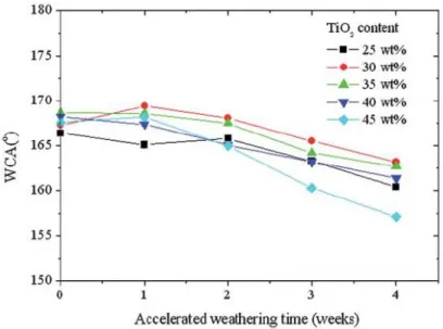
Ding et al. [45] have fabricated a superhydrophobic coating by blending fluorinated polysiloxane and different weight percentages of TiO2 nanoparticles. In
figure 2.15, after being subjected to an accelerated weathering test for 4 weeks, all superhydrophobic coatings showed a slight decrease in water contact angle. As they explained, the chemical bond of Si-O and C-F with bonding energy up to 460 and 485 kJ mol-1 respectively can neither be decomposed by photocatalytic TiO2 (band gap: 3.2
eV or 309 kJ mol-1) nanoparticles nor by UV light (314-419 kJ mol-1). However, fluorinated polysiloxane is quite expensive and not appropriate for practical applications.
Figure 2. 15 Changes of WCAs of the superhydrophobic coatings with different TiO2
contents under QUV accelerated weathering test [45]
In other words, we have already found a way to improve the UV stability of superhydrophobic coatings by grafting some chemical bonds with higher energy than that of ultraviolet and the band gap of a UV absorber (oxide nanoparticles).
As we discussed before, nanoparticles like TiO2 [42, 46, 47], ZnO [39, 48-50] and CeO2
[51] are well known for the role of inorganic UV absorbers. On the other hand, they could accelerate degradation of the polymer or fluoroalkyl-silane because of photocatalytic reaction. Therefore, people are becoming more and more interested in using other nanoparticles like SiO2 to suppress the photoactivity of TiO2, ZnO. This
should be another method that we can employ to develop UV-stable superhydrophobic coatings. Wang et al.[49] have successfully prepared a UV-stable superhydrophobic octadecyltrimethoxysilane (OTS) modified ZnO@SiO2 nanowire array by combining
comparing the contact angle of substrates with OTS-modified ZnO or ZnO@SiO2 NW
array placed under a Hayashi LA-410 light source, we can see the greatly improved UV durability of the latter one, as shown in figure 2.3.3. The UV source emits UV light in the range of 320-400 nm, whose intensity was maintained at 5.0 m W cm-2. As for the mechanism of UV stability, it could be illustrated that the insulating ~4.17nm SiO2 shell
was believed to effectively suppress the surface chemical reactions or surface reconstruction initiated by photo-generated hole-electron pairs in ZnO NWs. With the confinement effect, the photocatalytic oxidation reactions which generate hydroxyl
Figure 2. 16 Evolution of water CA on OTS-modified ZnO NW array (squares) and OTS-modified ZnO@SiO2 NW array (triangles) under UV irradiation[49]
radicals and groups will not happen. That is the principal of maintaining superhydrophobicity.They also applied the same coating on cotton textile and it is also
an ultraviolet-blocking surface as well [50]. However, the fabricating process is a little too complex for widespread use.
As another important photocatalytic material, TiO2 also shows strong oxidative
power after UV excitation with which it can completely decompose organic substances as well as UV-induced superhydrophilic transition. Isimjan et al.[47] revealed a superhydrophobic coating combining TiO2 nanoparticles with the low surface energy
chemical 1H, 1H, 2H, 2H-perfluorodecyltriethoxysilane (PTES) on a steel surface, with water contact angles as high as 165o. Nevertheless, the pure P25 TiO2 and PTES
mixture coating cannot resist UV light (315-400 nm, 100 mW/cm2) and the contact angle switched from ~170o to 0 in five hours.
![Figure 1. 1 The water drop in equilibrium state on a solid surface [2]](https://thumb-eu.123doks.com/thumbv2/123doknet/7634050.235862/21.892.264.634.736.991/figure-the-water-drop-equilibrium-state-solid-surface.webp)
![Figure 2. 1 The scheme for different bonding modes of SAM with APTES [12]](https://thumb-eu.123doks.com/thumbv2/123doknet/7634050.235862/31.892.254.673.283.724/figure-scheme-different-bonding-modes-sam-aptes.webp)
![Figure 2. 3 Cross-hatch tape adhesion test for coatings with 10–20 nm silica fillers. (a- (a-c) Hydrophobic surface and (d) superhydrophobic surface [31]](https://thumb-eu.123doks.com/thumbv2/123doknet/7634050.235862/40.892.267.624.156.520/figure-adhesion-coatings-fillers-hydrophobic-surface-superhydrophobic-surface.webp)

![Figure 2. 8 Contact angle and sliding angle on the metal/polymer composite surface as a function of abrasion cycles [35]](https://thumb-eu.123doks.com/thumbv2/123doknet/7634050.235862/44.892.239.656.115.426/figure-contact-sliding-polymer-composite-surface-function-abrasion.webp)
![Figure 2. 9 Contact angle and sliding angle on PTFE/PVDF composite surfaces as a function of abrasion cycles [36]](https://thumb-eu.123doks.com/thumbv2/123doknet/7634050.235862/45.892.239.653.683.981/figure-contact-sliding-composite-surfaces-function-abrasion-cycles.webp)
![Figure 2. 13 Reversible super-hydrophobic-super-hydrophilic transition of the as- as-prepared films under the alternation of UV irradiation and dark storage [43]](https://thumb-eu.123doks.com/thumbv2/123doknet/7634050.235862/51.892.237.654.109.335/figure-reversible-hydrophobic-hydrophilic-transition-prepared-alternation-irradiation.webp)
![Figure 2. 14 UV stability of a PFOS-treated rough silica thin film [40]](https://thumb-eu.123doks.com/thumbv2/123doknet/7634050.235862/52.892.243.653.263.563/figure-uv-stability-pfos-treated-rough-silica-film.webp)
![Figure 2. 16 Evolution of water CA on OTS-modified ZnO NW array (squares) and OTS-modified ZnO@SiO 2 NW array (triangles) under UV irradiation[49]](https://thumb-eu.123doks.com/thumbv2/123doknet/7634050.235862/54.892.236.655.540.888/figure-evolution-water-modified-squares-modified-triangles-irradiation.webp)
