HAL Id: hal-02948498
https://hal-univ-rennes1.archives-ouvertes.fr/hal-02948498
Submitted on 25 Sep 2020
HAL is a multi-disciplinary open access
archive for the deposit and dissemination of
sci-entific research documents, whether they are
pub-lished or not. The documents may come from
teaching and research institutions in France or
abroad, or from public or private research centers.
L’archive ouverte pluridisciplinaire HAL, est
destinée au dépôt et à la diffusion de documents
scientifiques de niveau recherche, publiés ou non,
émanant des établissements d’enseignement et de
recherche français ou étrangers, des laboratoires
publics ou privés.
Abu Sadat Md. Sayem, Roy B. V. B. Simorangkir, Karu P. Esselle, Raheel M.
Hashmi, Hangrui Liu
To cite this version:
Abu Sadat Md. Sayem, Roy B. V. B. Simorangkir, Karu P. Esselle, Raheel M. Hashmi, Hangrui
Liu. A Method to Develop Flexible Robust Optically Transparent Unidirectional Antennas
Uti-lizing Pure Water, PDMS and Transparent Conductive Mesh.
IEEE Transactions on Antennas
and Propagation, Institute of Electrical and Electronics Engineers, 2020, 68 (10), pp.6943-6952.
�10.1109/TAP.2020.2996816�. �hal-02948498�
ACCEPTED MANUSCRIPT
A Method to Develop Flexible Robust Optically
Transparent Unidirectional Antennas Utilizing Pure
Water, PDMS and Transparent Conductive Mesh
Abu Sadat Md. Sayem, Student member, IEEE, Roy B. V. B. Simorangkir, Member, IEEE, Karu P. Esselle,
Fellow, IEEE, Raheel M. Hashmi, Member, IEEE, and Hangrui Liu, Student member, IEEE
Abstract—A method to realize low-cost, optically transparent, flexible and unidirectional antennas is presented in this paper. The key to the method is making a flexible transparent reflector made using a new method- injection of pure water into a flexible transparent cavity that is made out of Polydimethylsiloxane (PDMS) polymer and integrating the flexible reflector with a flexible dipole made of transparent conducting mesh. This method is simple and inexpensive. Hence, it is useful for large scale production of transparent, flexible, robust and low-cost antennas as well as RF/microwave components for wearable body-area networks and other such systems that require flexible and transparent components. To validate the method, an antenna operating in the 2.45 GHz band was designed, fabricated and tested under various conditions. Its measured gain is 3.2 dBi and efficiency is 51%. To the best of our knowledge, this is the first water-based transparent flexible antenna. Due to the shielding effect of the water-based reflector, it produces low SAR in the human body when it is worn, as expected from a unidirectional antenna. Further, it is investigated and confirmed that the use of pure water in the reflector makes the antenna significantly more efficient as opposed to salt water.
Index Terms—Body area network, broadside, flexible, robust, smart city, uni-directional, water, wearable.
I. INTRODUCTION
With the rapid growth of unconventional applications, the demand for new antenna designs and new methods for an-tenna fabrication are increasing. It is undeniable that some new applications demand new antenna features; for example, wearable antennas should have low antenna-body coupling and antennas integrated on solar cell panels should be optically transparent. If a transparent antenna can be made flexible and compact, then it renders broad areas of application possibilities due to its unobtrusive appearance. Flexible and unobtrusive wearable devices enhance wearers’ comfort [1], [2], aesthetic appearance and, thus, increase the compliance This work was supported in part by the Australian Commonwealth Gov-ernment funded International Research Training Program Scholarship in Mac-quarie University, Australia. (Corresponding author: Abu Sadat Md. Sayem.) Abu Sadat Md. Sayem and Raheel M. Hashmi are with the School of Engineering, Macquarie University, Sydney, Australia. (E-mail: [email protected]).
R. B. V. B. Simorangkir is with the University of Rennes 1, CNRS, Institut d’Electronique et de T´el´ecommunications of Rennes (IETR)-UMR 6164, F-35000 Rennes, France and the School of Engineering, Macquarie University, Sydney, NSW 2109, Australia. (E-mail: [email protected]).
Karu P. Esselle is with the School of Electrical & Data Engineering, Uni-versity of Technology Sydney, Australia. (E-mail: [email protected]). Hangrui Liu is with the Department of Physics and Astronomy, Macquarie University, Sydney, Australia. (E-mail: [email protected]).
for long-term and continuous usage [3]. Visually imperceptible wearable devices can acquire health information seamlessly and pervasively in everyday life without compromising reg-ular activities. In particreg-ular, when there is a high chance of removing monitoring devices by the patients suffering from mental illness, it is significantly important to hide these devices from patients’ sight. Moreover, defence industry and security providers demand for unobtrusive conformal antennas that can be easily camouflaged, and optical transparency is considered as an efficient approach of achieving unobtrusiveness. The performance of the antenna hidden inside garments is affected by the dielectric constant of the fabric [4], [5] and the performance of the embroidered antennas deteriorates after washing [6], [7].
Besides wearable applications, flexible transparent antennas have another potential application in implementing reliable communication links for the rapidly growing mobile devices, especially in the context of Internet of Things (IoT) and Smart City Projects [8]. The rapid development of super-fast wireless technology invokes the need for high performance integrated networks, which imposes visual impacts and infrastructure challenges in urban areas. Installing conformal transparent antennas on existing infrastructure [8] such as window glasses, automobile windshields, display devices [9], street lights and solar cells [10] is an efficient solution of accommodating these large number of network access points without compromising aesthetics.
However, realization of optically transparent flexible an-tenna is highly challenging because of the unavailability of suitable materials and challenging fabrication processes. As can be found in the literature, the traditional transparent con-ductors used for the realization of transparent antennas can be classified into two major categories-(i) transparent conductive films, such as indium-tin-oxide (ITO) [11], zinc and silver (Ag) mixed multi-layer ITO (IZTO/Ag/IZTO) film [12], fluorine-doped tin oxide (FTO) [13] and silver-coated polyester (AgHT-8) film [14] and (ii) mesh conductors, such as tortuous copper micromesh [15] and silver grid layers (AgGL) [16]. The sheet resistance (Rs) and optical transparency (T) of these
conduc-tors are summarized in Table I, which shows that transparent conductive films have good transparency but suffer from poor conductivity (high sheet resistance) and mesh conductors have high electrical conductivity but their optical transparency is low. Thus, there exist a trade-off between sheet resistance and optical transparency when selecting these materials [8]. In
ACCEPTED MANUSCRIPT
PROPERTIES OF THE TRADITIONAL TRANSPARENT CONDUCTORS
Material Rs(Ω/sq) T (%)
Indium-tin-oxide (ITO) [11] 8.6 86 Multi-layer ITO (IZTO/Ag/IZTO) film [12] 4.99 81.1
Fluorine-doped tin oxide (FTO) [13] 4.81 69.2 Silver-coated polyester (AgHT-8) film [14] 8 80
Tortuous copper micromesh [15] 0.07 32 Silver grid layers (AgGL) [16] 0.018 54.5
addition, expensive and complicated fabrication processes are required to realize antennas from these materials. For many applications that require less expensive, transparent, flexible and robust antennas, new design and realization methods are still in need.
Recently, water has been utilized to realize transparent antennas owing to its availability, low cost and interesting electrical properties. Pure water provides almost 100% optical transparency within the visible light spectrum [17] and behaves as a dielectric material with high permittivity and high dielec-tric loss [18]. Although pure water has limited conductivity, when salt is added its conductivity increases significantly. In the literature, significant research efforts can be found on water-filled antennas where either pure water [18]–[20] or salt water [21]–[24] has been used. Moreover, some research efforts used both [25] for improved performance and some efforts investigated water-based reconfigurable antennas [26], [27].
Apart from the aforementioned water-based antennas, a new type of water-based antenna was introduced in [28], whose operating principle was described as a dense dielectric patch antenna (DDPA). Later, another water-based patch antenna was introduced in [29] where both the patch and ground were realized from water enclosed inside transparent plexiglass. The antenna was highly transparent except the small central disk-loaded feeding probe. This antenna operated at 2.4 GHz band with omnidirectional conical beam radiation patterns and demonstrated 35% impedance bandwidth. Its measured gain and efficiency varied from 1.5 to 4 dBi and 57% to 82%, respectively, over the operating band. The diameter of the antenna was 306 mm (∼2.45 λ0) and height was 37.6 mm
(∼0.3 λ0). Nevertheless, use of water to make a flexible and
transparent antenna is an area yet to be explored.
This paper addresses a key challenge in the realization of flexible, durable and transparent antennas with unidirectional radiation patterns. In this research effort, we have explored how electrical properties of water can be utilized to make a flexible reflector for an antenna by enclosing water in flexible polymer and further explain why pure water is more efficient than salt water for such flexible reflectors. To reduce the area occupied by conducting parts, which are often less transparent than non-conducting parts, we start with a flexible dipole antenna made of transparent conducting mesh as opposed to a microstrip patch. Indeed, when dipoles and other such anten-nas with bidirectional radiation patterns are used on a wearable system, they produce high levels of Specific Absorption Rate (SAR) due to the lack of a shield between the radiating element and the human body. To avoid this, the solution
using a new method - injection of pure water into a flexible transparent cavity that is made out of Polydimethylsiloxane (PDMS) polymer and integrating it to the flexible dipole to form a “shield” between the dipole and the body. To the best of our knowledge, this is the first flexible water-based transparent antenna ever reported. Moreover, the proposed fabrication method is inexpensive, simple, reproducible and is useful for low-cost production of optically transparent, flexible and durable antennas and potentially some RF/microwave components.
The water reflector directs dipole radiation primarily to the upper hemisphere like a typical microstrip patch antenna with a ground plane. The dipole occupies only a small fraction of the antenna area (2.5% in the prototype) and has about 70% optical transparency. To contain water without sacrificing its flexibility and transparency, a rectangular container is made from PDMS, which has extremely high flexibility, about 94% optical transparency [30], heat resistance and chemical stabil-ity. Thus, the remaining 97.5% of antenna area has optical transparency close to that of PDMS. The overall dimensions of this 2.45 GHz antenna is 60 mm × 60 mm × 14.5 mm (∼0.49 λ0 × 0.49 λ0 × 0.11 λ0). In fact, its area is less
than those of inflexible water-based 2.45 GHz antennas with unidirectional radiation patterns. This is the thinnest water-based unidirectional transparent antenna but it is thicker than some other transparent antennas realized from transparent thin films and mesh conductors. Due to its flexibility, transparency, unidirectional radiation pattern, durability and relatively small area, it has the potential for use in many applications men-tioned earlier including wearable systems. Its SAR is estimated and its bending performance is also examined in the paper.
II. ANTENNACONFIGURATION ANDOPERATION A. Antenna Configuration
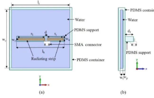
The configuration of the antenna is shown in Fig. 1. The radiating part of the antenna is a planar dipole strip, which is made of flexible transparent conductive mesh sheet, VeilShield from Less EMF, whose sheet resistance is 0.1 Ω/sq, optical transparency is nearly 72% and has a thickness of 0.057 mm. The dipole is fed at an offset feed point through an SMA connector. A pure water layer, enclosed inside a rectangular PDMS container, is placed underneath the radiating strip at an appropriate distance to act as a reflector and, thus, makes the radiation unidirectional. Another rectangular PDMS structure is attached to the container above it as a supporting structure to hold the radiating dipole above the water container. The dipole strip is attached to the support by using PDMS; strong integration of the mesh with PDMS ensures its stability in repeated bending operations [31]. Considering PDMS perco-lation into the mesh, an effective sheet resistance of 0.7 Ω/sq [31] was used to model the PDMS-conductive mesh composite in simulations during antenna design process. PDMS was found to have a relatively constant dielectric constant of 2.75 and an increasing loss tangent from 0.008 to 0.07 in the frequency range of 0.5 to 10 GHz, based on our measurements conducted with an Agilent 85070E Dielectric Kit. At the room
ACCEPTED MANUSCRIPT
Fig. 1. Antenna configuration: (a) top view, (b) side view.
Fig. 2. Measured relative permittivity and loss tangent of pure water.
temperature (23°C), its measured relative permittivity and loss tangent are plotted in Fig. 2. The optimized dimensions of the antenna, obtained using CST Microwave Studio, are listed in Table II.
B. Operating Principle
The operating principle of the proposed antenna is the utilization of a high-permittivity reflector plane on one side of a dipole radiator to transform its bidirectional radiation pattern to a unidirectional pattern. Fig. 3 illustrates the predicted 3-D radiation pattern of the antenna at 2.45 GHz and indicates its similarity to the pattern of a microstrip patch antenna. The antenna is linearly polarized. Pure water enclosed inside the PDMS container, shown in Fig. 1, is used as the reflector plane in our design. The interface between two media having
TABLE II
DIMENSIONS OF THE WATER-BASED ANTENNA
Parameter Description Value (mm) lr Length of the water layer 56
wr Width of the water layer 56
wt Thickness of the water layer 2.5
wp Thickness of the PDMS container 2
lh Length of the PDMS support 46
wh Width of the PDMS support 5
df Distance from reflector surface to radiator 8
sl Length of the left dipole strip 25.5
sr Length of the right dipole strip 15.5
wf Width of the dipole strip 2
d Gap between two strips of the dipole 2
Fig. 3. Predicted 3-D radiation pattern of the antenna at 2.45 GHz.
a large difference in permittivity provides an approximate boundary condition similar to an electric wall [28], [32]. As the permittivity of the water is much higher than that of the supporting PDMS layers and surrounding air, most of dipole radiation towards the reflector is reflected back from the interface [28], [32]. The phase angle of wave reflection coefficient φR [33] at the reflector plane and the electrical
distance between the reflector plane and radiator determine the interference properties between the reflected wave (from the reflector) and the direct radiated wave from the dipole in the upper hemisphere (z > 0). An optimum distance between the reflector and radiating dipole strip should be maintained to obtain constructive interference [33] and, thus, a unidirectional radiation pattern. The effects of the variation of the distance between the reflector and dipole strip and water layer dimensions are investigated later in parametric analysis section.
C. Comparison Between Pure-Water and Salt-Water Reflec-tors
In this design, high permittivity of water is used to generate reflection. At this point, it is logical to consider also a reflector filled with salt water as opposed to pure water. The predicted peak gains and radiation efficiencies of the antennas, one with a pure-water reflector and the other with a salt-water (relative permittivity 76 and electrical conductivity 3.6 S/m) reflector are shown in Fig. 4 and Fig. 5, respectively, for varying gap between the radiating strip and the reflector at the design frequency of 2.45 GHz. It can be noted, for practically useful values of gaps (i.e. less than 1 cm), a pure-water reflector leads to higher gain and efficiency than the salt-water reflector due to its lower loss. For the value of the gap selected for the final design (df = 8 mm), the difference in gain is approximately
2.8 dB, which is very significant, especially for a wearable system operating on wearable small batteries because it gives the opportunity to reduce transmitting power level by about 48% to achieve the same radio link quality and hence extends battery life. It is worth recalling here that the pure water layer behaves as an imperfect dielectric reflector and salt water layer behaves as an imperfectly conducting reflector. It turns out that
ACCEPTED MANUSCRIPT
Fig. 4. Comparison of the peak gain of the antenna at 2.45 GHz with pure-water and salt-pure-water reflectors for varying distance between the dipole and the reflector.
Fig. 5. Comparison of the radiation efficiency of the antenna at 2.45 GHz with pure-water and salt-water reflectors for varying distance between the dipole and the reflector.
pure-water reflector is more efficient than a salt-water reflector in this and similar applications.
III. PARAMETRICANALYSES
The key parameters that affect antenna performance are the length, width and thickness of the water layer and the distance between the water reflector and radiating strip. The effects of these parameters have been analyzed and the results are outlined here. For analyzing the effects of one parameter, other parameters are kept constant at the values given in Table II.
A. Effects of the Length of the Water Layer
The length of the water layer affects the radiation pattern and gain but does not affect the resonance frequency signif-icantly. The effects of the length of the water layer on the radiation patterns at 2.45 GHz frequency are illustrated in Fig. 6, which confirms the effectiveness of the length of the water as a reflector to direct radiation in broadside direction. With the increase of the length, back radiation decreases and front radiation increases accordingly, thus, antenna radiation pattern becomes more unidirectional.
Fig. 6. Effect of the length of the water layer on the radiation patterns at 2.45 GHz.
TABLE III
FRONT-TO-BACK(F/B)RATIO OF THE ANTENNA FOR VARIOUS WATER LAYER LENGTHS
lr(mm) 46 56 66 114
F/B (dB) 4.3 10 11.7 12.1
Fig. 7. Effect of the width of the water layer on the radiation patterns at 2.45 GHz.
The front-to-back (F/B) ratio of the radiation patterns of the antenna for various water reflector lengths are given in Table III. As expected, with the increase of the water reflector length, F/B ratio improves. This improvement is more significant at smaller lengths of the reflector. Aiming for a satisfactory F/B ratio and smaller antenna area, we have set the length at 56 mm.
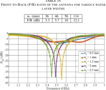
B. Effects of the Width of the Water Layer
Like the length of the water layer, the width also affects the radiation patterns and gain but does not affect the resonance frequency significantly. Fig. 7 depicts that wider water layer helps to increase F/B ratio.
The F/B ratio of the radiation patterns of the antenna for var-ious water reflector widths, shown in Table IV, confirms that with the increase of the reflector width, F/B ratio improves.
ACCEPTED MANUSCRIPT
TABLE IV
FRONT-TO-BACK(F/B)RATIO OF THE ANTENNA FOR VARIOUS WATER LAYER WIDTHS
wr(mm) 36 46 56 114
F/B (dB) 3.3 5.7 10 12.1
Fig. 8. Effect of the thickness of the water layer on the resonance frequency.
Like the effect of the reflector length, the improvement of the F/B ratio is more significant at smaller widths of the reflector. As depicted in Table IV, only 2.1 dB of improvement of the F/B ratio can be achieved for the increase of the width from 56 mm to 114 mm. To make the antenna compact, we have set the width at 56 mm.
C. Effects of the Thickness of the Water Layer
The thickness of the water layer influences the resonance frequency, matching and radiation patterns. The effect of the water layer thickness on antenna performance is due to reflection characteristics of a wave reflected from a multi-layer dielectric slab [34]. In our design, water and PDMS walls form multiple dielectric layers and due to its high dielectric constant water layer thickness affects antenna performance severely. Fig. 8 illustrates how the antenna resonance frequency and matching are affected by the water-layer thickness. A thicker water layer loads the dipole more and decreases its reso-nance frequency. The radiation patterns of the antenna at the corresponding resonance frequencies for various water layer thickness values are plotted in Fig. 9, which shows that only for very thin water layers, maximum radiation is towards the water layer (θ = 180°) due to the dielectric effect of PDMS, which has more effect than the water in these cases; otherwise maximum radiation is upwards (θ = 0°). The F/B ratio of the radiation patterns of the antenna for various water layer thickness values, given in Table V, confirms that for 0.5 and 1 mm thick water layers the F/B ratio is negative but for thicker water layers most of the radiation is directed towards upper hemisphere (positive F/B ratio).
D. Effects of the Distance between the Radiating Strip and Reflector Surface
The distance between the radiating strip and reflector sur-face is one of the most important parameters that determine the reflection characteristics as well as antenna performance,
Fig. 9. Effect of the thickness of the water layer on the radiation patterns. TABLE V
FRONT-TO-BACK(F/B)RATIO OF THE ANTENNA FOR VARIOUS WATER LAYER THICKNESS VALUES
wt(mm) 0.5 1 1.5 2 2.5
F/B (dB) -11.7 -9.9 7.7 7.8 10
particularly in terms of gain. The impact of the distance between the radiating strip and the water reflector on antenna peak gain is shown in Fig. 4. An optimal distance is required to get maximum gain at the target frequency of operation and from Fig. 4 that distance is approximately 17 mm (∼ λ0/8).
It is also noted that reducing this distance significantly to 8 mm will make the antenna a lot thinner and the reduction in gain is only 1 dB. Aiming for a reasonably thin antenna with good radiation performance, the distance between the radiating strip and reflector surface was chosen to be 8 mm (∼0.07 λ0),
for which a peak gain of 3.84 dBi and radiation efficiency of about 50% have been estimated at 2.45 GHz.
IV. FABRICATIONPROCESS A. Mold Fabrication
For fabricating the PDMS parts (i.e., the water container and the radiator supporting block), 3-D printed molds were used, whose geometries are shown in Fig. 10. Stereolithography (SLA) based 3-D printing machine (Form 2 from Formlabs) and Photopolymer resin were used to fabricate the molds. Designs of the molds were created by CAD software (Creo 5.0 plus) and then combined into one STL format file, which was then loaded to the 3-D printing machine using 3-D model preparation software (PreForm 2.17.1 from Formlabs). After fabricating the molds, they were kept in an oven (UF55, Mem-mert) at 75°C overnight for heating and drying to thoroughly cure the molds and to eliminate stickiness.
B. Antenna Fabrication
After fabricating the molds, antenna fabrication process was started. Fig. 10 illustrates some fabrication steps of the antenna. Mold 1 and mold 2 were used to fabricate the PDMS container to hold the water and mold 3 was used to fabricate the PDMS supporting block on which the dipole strip was placed. PDMS was prepared by mixing base and curing agent
ACCEPTED MANUSCRIPT
elastomer kit. Then, the uncured PDMS solution was poured into the molds and degassed in a vacuum desiccator to remove the air bubbles from the PDMS solution. Next, the PDMS solutions in the three molds were cured in an oven at 65°C for about 2 hours. The cured PDMS blocks were then peeled off from the molds. With a canal digged at the inner edges of mold 1 (see Fig. 10), the structure of cured PDMS layer obtained from mold 1 resembles a box without a cover. By attaching this structure to the PDMS structure obtained from mold 2, which is basically a simple rectangular slab, a hollow PDMS box was formed. The cured PDMS block from mold 3 was then attached on top of the hollow rectangular PDMS box. Uncured PDMS was used for all the attachments, which again required curing in an oven at 65°C for about 2 hours. After completing the fabrication of the PDMS structures, the radiating dipole strip was made by cutting the conductive mesh sheet manually by a sharp razor following the dimension of Fig. 1. The dipole strip was then attached to the supporting PDMS block by little amount of uncured PDMS and cured in an oven at 85°C for about 1 hour. After fabricating the antenna, the SMA connector was connected to the dipole feed point by using silver epoxy and it was cured again in the oven at 65°C for two hours. For strengthening the attachment of the SMA connector to the antenna, a section of the SMA connector flange was inserted into the PDMS block. At the last step, pure water was injected into the PDMS cavity by using a syringe.
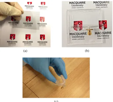
Fig. 11 shows the photos of the VeilShield and the fabricated prototypes of the antenna. Fig. 11(a) indicates reasonably high optical transparency of VeilShield. Fig. 11(b) confirms the high optical transparency of the fabricated prototype by the clear visibility of the printed logo and text through it. The small 43 mm × 2 mm radiating element, made from flexible conductive mesh sheet, takes up approximately 2.5% of the antenna area. The optical transparency of this small section is around 70% [31] and the rest of the antenna, composed of water and PDMS, has an optical transparency close to that of PDMS. Fig. 11 (c) demonstrates that the fabricated prototype is highly flexible and can be used in conformal operations without breakage. The proposed antenna can withstand harsh mechanical stress and can be used in wet and humid conditions. As is, it will freeze around 0°C but by adding a transparent anti-freeze, such as those added to car radiators, its freezing point may be brought down to very low temperatures. RF properties of such additives are not well known at present, so this aspect is beyond the scope of this paper.
V. EXPERIMENTALRESULTS
The performance of the antenna was tested in both free-space and on-phantom. The suitability of the antenna to operate near human body was examined by measuring its performance on a human-muscle-equivalent ultra-wide-band (UWB) homogeneous semi-solid flat phantom of dimensions 200 mm × 200 mm × 47 mm. The phantom was manufactured by adopting the technique as described in [35], by using
Fig. 10. Antenna fabrication process.
(a) (b)
(c)
Fig. 11. (a) A VeilShield sample demonstrating its transparency, (b) The antenna prototype, (c) Antenna bent to a very low radius.
deionized water (85.15%), agar (2.64%), polyethylene powder (PEP) (10.52%), sodium chloride (0.18%), TX-151 (1.46%) and sodium dehydroacetate (0.05%). The electrical properties of the phantom, measured using an Agilent 85070E Dielectric Probe Kit, imitates the electrical properties of human muscle in a wide frequency range, which includes the operating band of the antenna prototype. To represent the practical applications of the antenna on a human body with garment in between, a 5 mm gap was allowed between the antenna and the phantom by using a rectangular block of foam as shown in Fig. 12(a). For testing the robustness, the prototype was wrapped around the wrist of a human-hand-shaped phantom having a bending radius of 28 mm as shown in Fig. 12 (b). This phantom was also fabricated by using the same materials as the flat phantom.
ACCEPTED MANUSCRIPT
(a) (b)
Fig. 12. Photographs of the antenna measurement set-ups: (a) on a flat phantom, (b) wrapped on a human-hand-shaped phantom.
Fig. 13. Predicted and measured |S11| of the water antenna in free space, on
a flat phantom and under bending.
The predicted and measured results of the magnitude of input reflection co-efficient (|S11|) are illustrated in Fig. 13.
The |S11| measurements were accomplished with an Agilent
N5242A PNA-X. A strong correlation between the predicted and measured free-space results can be observed in the displayed results. In free space, the measured 10-dB return loss bandwidth of the antenna is approximately 170 MHz (∼2.37-2.54 MHz). Measured |S11| on flat-phantom shows
that the phantom has little effect on both resonance frequency and matching. However, the antenna still covers the desired 2.45 GHz band and good matching is still maintained. This demonstrates the shielding effect of the water reflector and the suitability of the antenna for operation in human-body environment. |S11| result on the bent-phantom indicates a
downward shift of the resonance frequency under bending due to the effect of the elongated current path. It is worth mentioning that the antenna is physically and electrically stable under bending and continues operation in the desired band in the bended case.
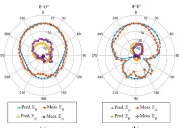
The normalized predicted and measured far-field radiation patterns of the antenna are plotted in Fig. 14. These patterns were measured using the NSI700S-50 spherical near-field antenna range at the Australian Antenna Measurement Facility in CSIRO, Marsfield, Sydney, Australia. The results show that the antenna produces a unidirectional radiation pattern, confirming the validity of the proposed design method. The measured peak gains and efficiencies of the antenna from 2 to 3 GHz are plotted and compared with the predicted values in Fig. 15 and Fig. 16, respectively. In the operating band, a maximum measured peak gain of 3.2 dBi is achieved with a
(a) (b)
Fig. 14. Predicted and measured normalized far-field radiation patterns (in dB) of the antenna: (a) XZ plane, (b) YZ plane.
Fig. 15. Predicted and measured peak gain of the antenna versus frequency.
Fig. 16. Predicted and measured radiation efficiency of the antenna versus frequency.
radiation efficiency of 51%. It is worth mentioning that the fabrication inaccuracy and the presence of tiny air bubbles have contributed to small discrepancies between the predicted and measured results. Moreover, the silver-epoxy connection between the SMA connector and the conductive mesh dipole may also have affected some measured results.
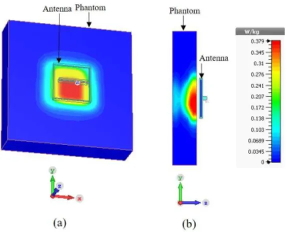
Finally, to explore the effectiveness of shielding provided by the water reflector and compatibility of the new antenna with wearable wireless systems, its SAR was numerically assessed by placing the antenna 5 mm above a 200 mm × 200 mm × 47 mm human-muscle-equivalent flat-phantom. The SAR
ACCEPTED MANUSCRIPT
Fig. 17. SAR distribution in human-muscle-equivalent flat-phantom at 2.45 GHz: (a) 3-D view, (b) cross-sectional view.
was computed in CST Microwave Studio by applying 0.1 W input power and averaged over 10 g of tissue. The numerically computed maximum 10 g-averaged SAR was 0.379 W/kg, which is below the SAR limit of 2 W/kg as specified in IEEE C95.1-2005 standard [36]. So, the water reflector provides effective shielding against the antenna’s back radiation towards body and it functions like the metal ground plane in a patch antenna. The SAR investigation demonstrates that this antenna can be used in wearable applications and input power level can be increased to about 0.5 W without exceeding the IEEE SAR limit. Fig. 17 shows the predicted SAR distribution in the human-muscle-equivalent flat phantom. It is worthy to mention here that the thickness of the water layer impacts the SAR; for 4.5 mm thick water layer, the computed maximum 10 g-averaged SAR reduces to 0.261 W/Kg. Moreover, the body itself can serve as a water-based reflector, without needing the water bolus, but the resulting high SAR and low efficiency make such an arrangement inappropriate for wearable wireless systems.
VI. CONCLUSION
A novel design of a highly flexible, durable and optically transparent antenna with a patch-like unidirectional radiation pattern has been demonstrated. The high permittivity of pure water, enclosed inside flexible transparent polymer cavity, is utilized to make a reflector to transform the bidirectional radiation pattern of a dipole to a unidirectional broadside pattern. The small dipole strip itself is made from flexible transparent conductive mesh, and hence, the antenna is highly flexible, robust and transparent. A comparison between salt-water and pure-salt-water reflectors confirms that both can function as a reflector but a pure-water reflector leads to a significantly higher antenna gain and efficiency when compared with a salt-water reflector, especially for small gaps between the radiating dipole and the reflector, due to excessive loss in salt water. The antenna is made from low cost and readily available materials using 3-D printed molds. The fabrication process is simple, inexpensive and reproducible. This antenna has smaller lateral dimensions than other reported (inflexible) water-based antennas having unidirectional radiation patterns.
transparency, good RF performance and ease of fabrication, the demonstrated method is appropriate for production of robust flexible transparent antennas as well as some flexible transparent RF components.
ACKNOWLEDGMENT
The authors would like to thank Dr. Shilun Feng, Nanyang Technological University, Singapore for his assistance in mold fabrication. The authors are also grateful to Dr. Rajas Prakash Khokle for his co-operation in antenna measurements.
REFERENCES
[1] Y. Zheng, X. Ding, C. C. Y. Poon, B. P. L. Lo, H. Zhang, X. Zhou, G. Yang, N. Zhao, and Y. Zhang, “Unobtrusive Sensing and Wearable Devices for Health Informatics,” IEEE Transactions on Biomedical Engineering, vol. 61, no. 5, pp. 1538–1554, May 2014.
[2] R. Paradiso, G. Loriga, and N. Taccini, “A wearable health care system based on knitted integrated sensors,” IEEE Transactions on Information Technology in Biomedicine, vol. 9, no. 3, pp. 337–344, Sep. 2005. [3] M. Poh, N. C. Swenson, and R. W. Picard, “A Wearable Sensor for
Unobtrusive, Long-Term Assessment of Electrodermal Activity,” IEEE Transactions on Biomedical Engineering, vol. 57, no. 5, pp. 1243–1252, May 2010.
[4] D. L. Paul, H. Giddens, M. G. Paterson, G. S. Hilton, and J. P. McGeehan, “Impact of Body and Clothing on a Wearable Textile Dual Band Antenna at Digital Television and Wireless Communications Bands,” IEEE Transactions on Antennas and Propagation, vol. 61, no. 4, pp. 2188–2194, April 2013.
[5] C. Hertleer, H. Rogier, L. Vallozzi, and L. Van Langenhove, “A Textile Antenna for Off-Body Communication Integrated Into Protective Cloth-ing for Firefighters,” IEEE Transactions on Antennas and Propagation, vol. 57, no. 4, pp. 919–925, April 2009.
[6] M. Guibert, A. Massicart, X. Chen, H. He, J. Torres, L. Ukkonen, and J. Virkki, “Washing reliability of painted, embroidered, and electro-textile wearable RFID tags,” in 2017 Progress in Electromagnetics Research Symposium - Fall (PIERS - FALL), Nov 2017, pp. 828–831. [7] M. Toivonen, T. Bj¨orninen, L. Syd¨anheimo, L. Ukkonen, and Y.
Rahmat-Samii, “Impact of Moisture and Washing on the Performance of Em-broidered UHF RFID Tags,” IEEE Antennas and Wireless Propagation Letters, vol. 12, pp. 1590–1593, 2013.
[8] R. B. Green, M. Guzman, N. Izyumskaya, B. Ullah, S. Hia, J. Pitchford, R. Timsina, V. Avrutin, U. Ozgur, H. Morkoc, N. Dhar, and E. Topsakal, “Optically Transparent Antennas and Filters: A Smart City Concept to Alleviate Infrastructure and Network Capacity Challenges,” IEEE Antennas and Propagation Magazine, vol. 61, no. 3, pp. 37–47, June 2019.
[9] W. Hong, S. Lim, S. Ko, and Y. G. Kim, “Optically Invisible Antenna Integrated Within an OLED Touch Display Panel for IoT Applications,” IEEE Transactions on Antennas and Propagation, vol. 65, no. 7, pp. 3750–3755, July 2017.
[10] T. Peter, T. A. Rahman, S. W. Cheung, R. Nilavalan, H. F. Abutarboush, and A. Vilches, “A Novel Transparent UWB Antenna for Photovoltaic Solar Panel Integration and RF Energy Harvesting,” IEEE Transactions on Antennas and Propagation, vol. 62, no. 4, pp. 1844–1853, April 2014.
[11] F. Colombel, X. Castel, M. Himdi, G. Legeay, S. Vigneron, and E. M. Cruz, “Ultrathin metal layer, ITO film and ITO/Cu/ITO multilayer towards transparent antenna,” IET Sci., Measure. Tech., vol. 3, no. 3, pp. 229–234, May 2009.
[12] S. Hong, S. H. Kang, Y. Kim, and C. W. Jung, “Transparent and flexible antenna for wearable glasses applications,” IEEE Transactions on Antennas and Propagation, vol. 64, no. 7, pp. 2797–2804, July 2016. [13] S. Sheikh, M. Shokooh-Saremi, and M. Bagheri-Mohagheghi, “Transpar-ent microstrip patch antenna based on fluorine-doped tin oxide deposited by spray pyrolysis technique,” IET Microwaves, Antennas Propagation, vol. 9, no. 11, pp. 1221–1229, 2015.
[14] S. Y. Lee, M. Choo, S. Jung, and W. Hong, “Optically Transparent Nano-Patterned Antennas: A Review and Future Directions,” Applied Sciences, vol. 8, no. 6, 2018. [Online]. Available: https://www.mdpi.com/2076-3417/8/6/901
ACCEPTED MANUSCRIPT
[15] T. Jang, C. Zhang, H. Youn, J. Zhou, and L. J. Guo, “Semitransparent and flexible mechanically reconfigurable electrically small antennas based on tortuous metallic micromesh,” IEEE Trans. Antennas Propag., vol. 65, no. 1, pp. 150–158, Jan 2017.
[16] J. Hautcoeur, F. Colombel, X. Castel, M. Himdi, and E. M. Cruz, “Radiofrequency performances of transparent ultra-wideband antennas,” Prog. in Electromag. Res. C, vol. 22, pp. 259–271, 2011.
[17] R. Saidur, T. Meng, Z. Said, M. Hasanuzzaman, and A. Kamyar, “Evaluation of the effect of nanofluid-based absorbers on direct solar collector,” International Journal of Heat and Mass Transfer, vol. 55, no. 21, pp. 5899 – 5907, 2012. [Online]. Available: http://www.sciencedirect.com/science/article/pii/S0017931012004188 [18] S. G. O’Keefe and S. P. Kingsley, “Tunability of liquid dielectric
resonator antennas,” IEEE Antennas and Wireless Propagation Letters, vol. 6, pp. 533–536, 2007.
[19] R. Zhou, H. Zhang, and H. Xin, “A compact water based dielectric resonator antenna,” in 2009 IEEE Antennas and Propagation Society International Symposium, June 2009, pp. 1–4.
[20] R. Zhou and H. Zhang and H. Xin, “Liquid-based dielectric resonator antenna and its application for measuring liquid real permittivities,” IET Microwaves, Antennas Propagation, vol. 8, no. 4, pp. 255–262, March 2014.
[21] C. Hua and Z. Shen, “Shunt-excited sea-water monopole antenna of high efficiency,” IEEE Transactions on Antennas and Propagation, vol. 63, no. 11, pp. 5185–5190, Nov 2015.
[22] C. Hua, Z. Shen, and J. Lu, “High-efficiency sea-water monopole antenna for maritime wireless communications,” IEEE Transactions on Antennas and Propagation, vol. 62, no. 12, pp. 5968–5973, Dec 2014. [23] L. Xing, Y. Huang, S. S. Alja’afreh, and S. J. Boyes, “A monopole water antenna,” in 2012 Loughborough Antennas Propagation Conference (LAPC), Nov 2012, pp. 1–4.
[24] H. Fayad and P. Record, “Broadband liquid antenna,” Electronics Letters, vol. 42, no. 3, pp. 133–134, Feb 2006.
[25] M. Wang and Q. Chu, “High-efficiency and wideband coaxial dual-tube hybrid monopole water antenna,” IEEE Antennas and Wireless Propagation Letters, vol. 17, no. 5, pp. 799–802, May 2018. [26] J. Liang, G. Huang, K. Qian, S. Zhang, and T. Yuan, “An
azimuth-pattern reconfigurable antenna based on water grating reflector,” IEEE Access, vol. 6, pp. 34 804–34 811, 2018.
[27] Z. Hu, Z. Shen, and W. Wu, “Reconfigurable leaky-wave antenna based on periodic water grating,” IEEE Antennas and Wireless Propagation Letters, vol. 13, pp. 134–137, 2014.
[28] Y. Li and K. Luk, “A water dense dielectric patch antenna,” IEEE Access, vol. 3, pp. 274–280, 2015.
[29] J. Sun and K. Luk, “A wideband low cost and optically transparent water patch antenna with omnidirectional conical beam radiation patterns,” IEEE Transactions on Antennas and Propagation, vol. 65, no. 9, pp. 4478–4485, Sept 2017.
[30] S. Sun, Z. Pan, F. K. Yang, Y. Huang, and B. Zhao, “A transparent silica colloidal crystal/PDMS composite and its application for crack suppression of metallic coatings,” Journal of Colloid and Interface Science, vol. 461, pp. 136 – 143, 2016. [Online]. Available: http://www.sciencedirect.com/science/article/pii/S0021979715301855 [31] A. S. M. Sayem, R. B. V. B. Simorangkir, K. P. Esselle, and R. M.
Hashmi, “Development of Robust Transparent Conformal Antennas Based on Conductive Mesh-Polymer Composite for Unobtrusive Wear-able Applications,” IEEE Transactions on Antennas and Propagation, vol. 67, no. 12, pp. 7216–7224, Dec 2019.
[32] H. W. Lai, K. Luk, and K. W. Leung, “Dense Dielectric Patch Antenna-A New Kind of Low-Profile Antenna Element for Wireless Communica-tions,” IEEE Transactions on Antennas and Propagation, vol. 61, no. 8, pp. 4239–4245, Aug 2013.
[33] L. Peng, J.-y. Xie, K. Sun, X. Jiang, and S.-m. Li, “Resonance-Based Reflector and Its Application in Unidirectional Antenna with Low-Profile and Broadband Characteristics for Wireless Applications,” Sensors, vol. 16, no. 12, 2016. [Online]. Available: https://www.mdpi.com/1424-8220/16/12/2092
[34] K. P. Thakur and W. S. Holmes, “Reflection of plane wave from multi-layered dielectrics,” in APMC 2001. 2001 Asia-Pacific Microwave Conference (Cat. No.01TH8577), vol. 2, Dec 2001, pp. 910–913 vol.2. [35] K. Ito, K. Furuya, Y. Okano, and L. Hamada, “Development and char-acteristics of a biological tissue-equivalent phantom for microwaves,” Electronics and Communications in Japan (Part I: Communications) banner, vol. 84, no. 4, pp. 67–77, Apr. 2001.
[36] “IEEE Standard for Safety Levels with Respect to Human Exposure to Radio Frequency Electromagnetic Fields, 3 kHz to 300 GHz,” IEEE Std C95.1-2005 (Revision of IEEE Std C95.1-1991), pp. 1–238, April 2006.