Any correspondence concerning this service should be sent to the repository administrator: [email protected]
Official URL: http://dc.engconfintl.org/fluidization_xiv/
This is an author-deposited version published in: http://oatao.univ-toulouse.fr/ Eprints ID: 10529
To cite this version:
Neau, Hervé and Fede, Pascal and Laviéville, Jérôme and Simonin, Olivier High
performance computing (HPC) for the fluidization of particle-laden reactive
flows. (2013) In: 14th International Conference on Fluidization - From
Fundamentals to Products (2013), 26 May 2013 - 31 May 2013 (Netherlands).
O
pen
A
rchive
T
oulouse
A
rchive
O
uverte (
OATAO
)
OATAO is an open access repository that collects the work of Toulouse researchers and makes it freely available over the web where possible.
HIGH PERFORMANCE COMPUTING (HPC) FOR THE
FLUIDIZATION OF PARTICLE-LADEN REACTIVE FLOWS
Hervé Neaua,b*, Pascal Fedea,b, Jérôme Laviévillecand Olivier Simonina,b
a Université de Toulouse; INPT, UPS; IMFT; F-31400 Toulouse, France b
CNRS ; Institut de Mécanique des Fluides de Toulouse; Allée du Professeur Camille Soula, F-31400 Toulouse, France
c
EDF Recherche & Développement; DMFEE; F-78401, Chatou, France *T: +33 5 34 32 29 23; E: [email protected]
ABSTRACT
The present paper shows the parallel computing performance (up to 4,096 cores) of a numerical solver for simulation of dense reactive multiphase reactive flow such as fluidized bed reactor. NEPTUNE_CFD V1.08 is a parallelized unstructured code solving unsteady Eulerianmulti-fluid approach.The mesheshaveupto 38,000,000 cells. The simulations show an excellent scalability up to 2,536 cores.
INTRODUCTION
Dilute and dense particle-laden reactive flows are encountered in a wide range of industrial applications such as coal combustion, catalytic polymerization or uranium fluoration. The numerical modeling with specific focus on the hydrodynamic of fluidized beds has been a major topic of research over last two decades. Nowadays, it is possible to perform realistic 3D industrial configuration simulations using unsteady Eulerian multi-fluid approach for monodisperse or polydisperse reactive particle mixtures (Igci et al. (1), Wang et al. (2), Delloume et al. (3)). Such an approach is implemented in the unstructured parallelized code NEPTUNE_CFD V1.08. NEPTUNE_CFD is a multiphase flow software developed in the framework of the NEPTUNE project, financially supported by CEA, EDF, IRSN and AREVA-NP. As shown by Parmentier et al. (4), the effective numerical simulation of fluidized beds may be very expensive (mesh and CPU time), both at industrial and laboratory scales, in particular because of the 3D unsteady structures of small sized (clusters or bubbles). It may need from thousands to millions of computational hours on supercomputer and consequently requires the use of High Performance Computing (HPC). Moreover, recent hardware developments (interconnection network, multi-core, cache) have strongly increased the computer performances and efficiency. Parallel computations using meshes of several millions of cells are currently running. In this study, we make an evaluation of NEPTUNE_CFD parallel performances up to 4,096 cores on a schematic configuration (3D uniform granular shear flow) and an industrial scale reactor of gas-solid fluidized bed.
NEPTUNE_CFD
The main numerical characteristics of NEPTUNE_CFD V1.08 are unstructured meshes with all types of cell, non-conforming connections, cell-center type finite volume method, calculation of co-localized gradients with reconstruction methods and distributed-memory parallelism by domain decomposition (MPI parallelization).
In a previous study, NEPTUNE_CFD’s scalability has been checked up to 1,024 cores (Neau et al. (5)). The kernel module (numerical solver) is written in Fortran 77 and C (ANSI 1989). NEPTUNE_CFD relies one compulsory library (BFT) for memory and Input/Output (I/O) management as well as specific utilities.
The NEPTUNE_CFD mathematical modeling of gas-solid turbulent flows is based on multi-fluid Eulerian equations derived in the frame of an original joint fluid-particle PDF approach. In the proposed modeling approach, separate mean transport equations (mass, momentum, and fluctuating kinetic energy) are solved for each phase and coupled through inter-phase transfer terms. For more details on mathematical modeling we refer to Simonin (6), and on fluidized bed simulations we refer to Balzer et al. (7), Gobin et al. (8).
The partial differential equations are discretized with a 2nd order centered scheme and the solution is time-advanced by a 1st order scheme. The algorithm is based on an elliptic semi-implicit fractional step method using iterative linear solvers or direct matrix inversion (Méchitoua et al. (9)). The algorithm accounts for density variation as a function of pressure, enthalpy and mass fraction of species.
PARALLEL SUPERCOMPUTER DESCRIPTION
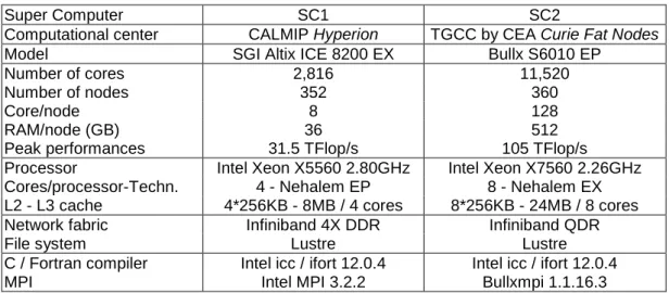
Numerical simulations have been carried out on 2 clustersinproduction(cf.Table1): - SC1:SGIAltixICE8200-EXbasedonIntelXeonX5560QuadCoreprocessors, - SC2:Bullx S6010 based on Intel Xeon X7560 Eight Core processors.
Super Computer SC1 SC2
Computational center CALMIP Hyperion TGCC by CEA Curie Fat Nodes
Model SGI Altix ICE 8200 EX Bullx S6010 EP
Number of cores 2,816 11,520
Number of nodes 352 360
Core/node 8 128
RAM/node (GB) 36 512
Peak performances 31.5 TFlop/s 105 TFlop/s Processor Intel Xeon X5560 2.80GHz Intel Xeon X7560 2.26GHz Cores/processor-Techn. 4 - Nehalem EP 8 - Nehalem EX L2 - L3 cache 4*256KB - 8MB / 4 cores 8*256KB - 24MB / 8 cores Network fabric Infiniband 4X DDR Infiniband QDR
File system Lustre Lustre
C / Fortran compiler Intel icc / ifort 12.0.4 Intel icc / ifort 12.0.4
MPI Intel MPI 3.2.2 Bullxmpi 1.1.16.3
Table 1: Super computer description. SIMULATION OF A 3D GRANULAR UNIFORM SHEAR FLOW
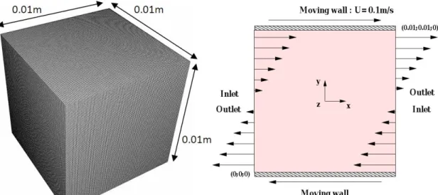
This case is a 3D isothermal granular shear flow of a monodisperse and a binary solid particle mixture (shear rate = 20 s-1). The computational domain is a cubic box of length Hcube = 0.01 m. The schematic of the system is shown by Figure 1. The
solid and gas material properties are given by in Table 2.
For the bidisperse case, we choose a ratio of particle diameter (coarse/fine) used in industrial fluidized bed of catalytic polymerization. The gas phase is laminar and the particle agitation model is accomplished by solving an equation for the particle turbulent agitation. Gravity is not taken into account. According to a largeparticleto gasdensityratioonlythedragforceistakenintoaccount.
Figure 1: Sketch and mesh (1,000,000 of cells) of a 3D granular uniform shear flow.
Monodisperse Binary solid particle mixture Phase Gas Solid Solid 1 Solid 2 Density (kg·m-3) 1 1000 1000 1000 Viscosity ×10-5 (Pa·s) 1 - - -
Diameter (µm) - 350 350 40 Solid volume fraction - 0.3 0.3 0.001 Restitution coefficient - 0.8 0.8 0.8
Table 2: Powder and gas properties.
We employed two different regular meshes with uniform size hexahedra: - 1M mesh: 1,000,000 cells, ∆l = 10-4 m, 100 cells per direction (Figure 1),
- 38M mesh: 37,933,056 cells, ∆l = 3.10-5 m, 336 cells per direction.
Three boundary conditions are used:
- right-side and left-side, inlet-outlet condition for particles and gas with imposed velocity (m·s-1): = 20 × − ,
- front-side and back-side, symmetry condition for particle and gas,
- top-side and bottom-side, moving wall: = 20 × − . Moving wall is a no-slip wall boundary (gas and particle): , = , = and = 0. An adaptative time step is used (computed from Courant and Fourier criteria). The following iterative solvers have been selected: jacobi for the velocity, conjugated gradient for the pressure and biconjugate gradient stabilized for the volume fraction.
For the monodisperse test case we solve 9 partial differential equations: PDE (mass balance, momentum transport, particle turbulence) and 14 for the bi-dispersed case.
For such a configuration, the mathematical model has a 0D analytical solution which can be compared with the numerical solution given by NEPTUNE_CFD. So, we have solved the equations of the mathematical modeling in the frame of 0D approach and the corresponding predictions are given by Table 3.
Monodisperse Binary particle mixture Solid Solid 1 Solid 2 Solid volume fraction 0.300 0.300 0.001 Particle fluctuating kinetic energy (m2·s-2) 2.66 10-5 2.62 10-5 2.962 10-6 Particle kinetic viscosity (kg·m-1·s-1) 6.21 10-4 6.16 10-4 5.60 10-4 Particle collisional viscosity (kg·m-1·s-1) 9.88 10-4 9.87 10-4 6.39 10-5
Table 3: 0D approach predictions. Numerical results and discussion
After a transient phase, numerical simulations converge to stationary state. 3D unsteady numerical simulation results of monodisperse case with 1M mesh agree with0D predictions (Table4). TheaccuracyofNEPTUNE_CFD numerical results is excellent and independent of parallelization, core number or mesh size.
NEPTUNE_CFD performances are evaluated on a restart simulation of 1,000 additional iterations after transient step on the 1M mesh and 200 additional iterations on the 38M mesh. We used the "CPU_TIME" intrinsic fortran sub-routine to measure the different CPU times per core. The following analysis is based on the averaged values of effective CPU time (at least 3 times for each case).
0D NEPTUNE_CFD minimum maximum Solid volume fraction 0.300 0.300 0.301 Particle fluctuating kinetic energy (m2·s-2) 2.66 10-5 2.65 10-5 2.66 10-5 Particle kinetic viscosity (kg·m-1·s-1) 6.21 10-4 6.19 10-4 6.21 10-4 Particle collisional viscosity (kg·m-1·s-1) 9.88 10-4 9.88 10-4 9.90 10-4
Table 4: 0D approach and NEPTUNE_CFD predictions for monodisperse case. Monodisperse case: 1,000,000 and 37,933,056 cell meshes
Evaluation of NEPTUNE_CFD parallel performances is realized on the 1M mesh from 8 to512cores on SC1/SC2andon the38M meshfrom128to 4096cores on SC2.
The speedup is defined as the ratio between the elapsed time to execute a program on one node (ref=1node=8cores on SC1 and ref’=1node=128cores on SC2) and ona setofconcurrent n nodes(n×ref)andthe efficiency is defined as the ratio between speedup and n: = !
" = # $ %
" =
&
where '() is the effective core CPU time of the parallel job on one node (ref) and ' is the effective core CPU time of the parallel job on n nodes (n×ref). To plot on a
same graph SC1 and SC2 results on the 1M mesh, we set a common reference:
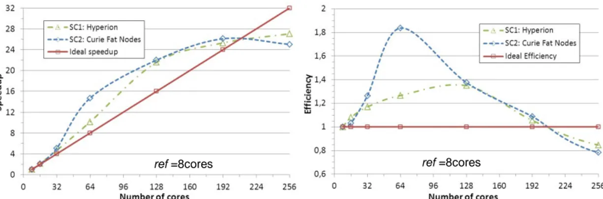
ref=8cores. NEPTUNE_CFD speedup and parallelism efficiency are depicted in
Figure 2. The solid line represents the ideal speedup and efficiency. With the 1M mesh, from 16 to 192 cores, the speedup is greater or equal to the linear speedup (say, super-linear speedup). As a consequence, the efficiency is found greater than 1. Such a behavior comes from cache effect and memory band width.
Beyond 192 cores, the efficiency decreases significantly. For a large number of cores it is mainly caused by MPI communication overhead and unbalancing load.
Figure 2: NEPTUNE_CFD speedup and efficiency (1M mesh – ref = 8 cores)
Restitution time of a simulation is divided into computation time, communication and waiting time (send/receive/barrier MPI) and Input/Output time (zero in this case). Basically increasing of core number corresponds to decreasing of cell number per core. However a decrease of computation time per core leads to an increase of communication time between cores. The core limit number is reached when communication time increases quicker than the decrease of computation time. Thus, there is an optimal number of cores fora given mesh anda given number of PDE. For the simulation using 1M mesh and solving 10 PDE, the performances are excellent while cell number per core is greater than 10,000 and good up to 5,200 cells per core that is to say up to 192 cores. The restitution time decreases up to 256 cores (4,000 nodes per core).
We emphasized that a more important effective CPU times on SC2 than on SC1 (about 1.6 times). This effect may be attributed to processor frequency, to computer architecture (interconnection network) and to implementations of MPI.
To improve NEPTUNE_CFD performance evaluation, we perform numerical simulations on SC2 with a mesh including 37,933,056 hexahedra using from 1 to 32 nodes (128 to 4,096 cores). As CPU times are important, performances are evaluated on a restart simulation of 200 additional iterations after transient phase.
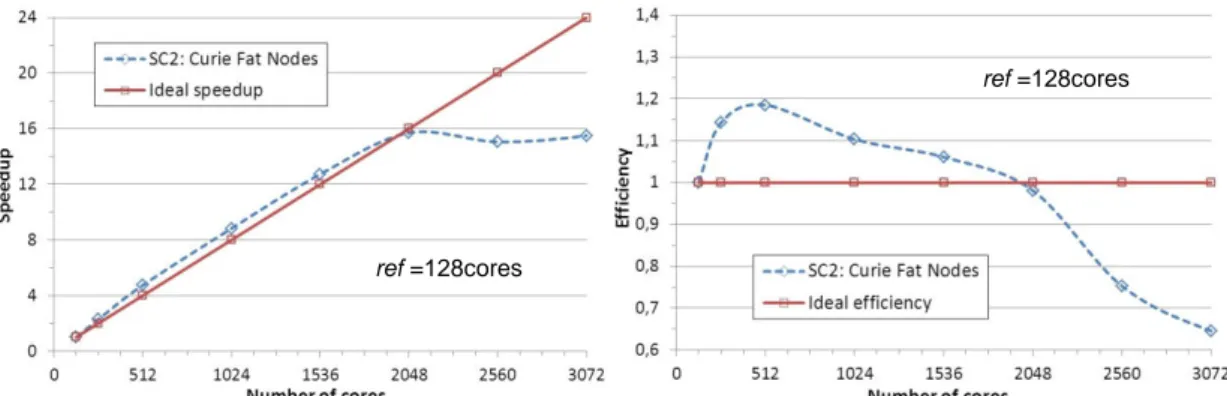
Figure 3 shows the speedup and efficiency, obtained for the mesh 38M, defined with
ref=128cores. We observe an excellent HPC efficiency even for large core number
(2,048 cores, 16 nodes). The speedup is super-linear up to 1,536 cores and linear for 2,048 cores. Efficiency is also greater or equal to 1. This studyconfirms the very good parallel performances of NEPTUNE_CFD on Nehalem clusters.
Nevertheless, with the 38M mesh, performance degradation begins when cell number per core is lower than 18,500 instead 10,000 in the case with the 1M mesh. This augmentation could be explained by implementation of the message passing library (MPI) and by computer architecture. Previous studies with MPINSIDE (Neau et al. (5)) have shown that MPI communications (barrier before MPI Allreduce) due to iterative solvers increase quickly with core number. Bullxmpi is known to be not very efficient for these MPI synchronization steps on this architecture (Fat Nodes). The large number of cores per node (128 on SC2) and the interconnection network (InfiniBand QDR) increase this limitation (a lot of MPI communications on a low I/O unit number managed by a MPI that can be improved).
ref =8cores ref =8cores
Figure 3: NEPTUNE_CFD speedup and efficiency (monodisperse - 38M mesh).
NEPTUNE_CFD strong scaling is excellent up to 2,048 cores on SC2 in condition of respect of minimum cell number per core (18,500 cells per core). Using a cluster with “thin”nodesandanefficientMPI,weshouldobtainscalabilityupto3,584cores.
Bidisperse case: 37,933,056 cell mesh
This case is the same 3D isothermal granular shear flow but with a binary solid mixture described in Table 2. Simulations are performed on the 38M mesh from 128 to 4,096 cores on SC2. Figure 4 depicts NEPTUNE_CFD speedup (ref=128cores). NEPTUNE_CFD performances are excellent up to 2,560 cores (i.e.while cell number per core is greater than 14,800).
For this bidisperse numerical simulation, NEPTUNE_CFD solve 16 PDE instead of 10 in the previous case. So, the computation versus communication balance is better and the minimum number of cells per core decreases.
Figure 4: NEPTUNE_CFD speedup
(bidisperse – 38M mesh).
This study of uniform granular (mono/bidisperse) shear flow shows accuracy and excellent scalability of NEPTUNE_CFD for large enough problem sizes.
INDUSTRIAL CASE: 3D GAS-SOLID FLUIDIZED BED REACTOR
The 2nd case is a 3D unsteady dense fluidized bed at industrial scale. The reactor is about 30 meter high and 5 meter wide (Figure 5). The powder / gas properties and operating points are given in Table 5. For the gas turbulence modeling, we use a standard k-ε model
extended to fluid-particle flows. For the solid phase, a coupled transport equation system is solved on particle fluctuating kinetic energy andfluid-particlefluctuatingvelocitycovariance.
Figure 5: Mesh of industrial fluidized bed.
ref =128cores
5m 30m ref =128cores
Only the drag and buoyancy (Archimedes) forces were accounted for fluid/particle momentum transfer. At the bottom, the
fluidization grid is an inlet for the gas with imposed fluidization velocity Vf = 0.67 m·s-1
anda wall for solid. At the top, we defined 2 free outlets for gas and solid. The wall-type boundary condition is friction for gas and slip for solid. Figure 5 details the 3M reactor mesh (O-grid) using 3,150,716 hexaedra with
∆x=∆y~30 mm, ∆z=90 mm.
Phase Gas Solid Density (kg·m-3) 21 850 Viscosity ×10-5 (Pa·s) 1.54 - Pressure (bar) 20 - Median diameter (µm) - 1600 Solid mass (kg) - 80,000 Restitution coefficient - 0.9
Table 5: Powder and gas properties.
NEPTUNE_CFD HPC is evaluated on a restart simulation of 500 iterations after fluidized bed destabilization. Simulations were carried out only on the cluster SC1. The code speedup is depicted in Figure
6. Parallel performances are very good up to 384 cores. The restitution time decreases up to 512 cores. For this simulation solving 12 equations, NEPTUNE_CFD HPC is excellent while cellnumberpercoreishigher than8,200. This simulation of a fluidized bed reactor illustrates perfect NEPTUNE_CFD scalability at industrial scale.
Figure 6: NEPTUNE_CFD speedup (fluidized bed reactor - 3M mesh).
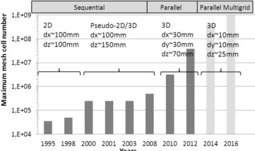
If we consider such a 3D reactor (30 m, 5 m), if we set a maximum CPU time per core of 15 days, we can evaluate the maximum number of mesh cells we can use to perform a simulation of physical time 20 s. Based on our experience of Eulerian multi-fluid codes, Figure 7 shows the past and future evolution of this maximum number of mesh cells between 1995 and 2016.
Figure 7: Evolution of code HPC capabilities on fluidizedbedreactor.
Between 1995 and 2008 the evolution was due to hardware performance increasing (processor, RAM). Since 2008, parallelization by decomposition domain allows use
of mesh hundred times bigger. The current step is the massively parallel computation (thousands of cores) with multigrid solvers.
CONCLUSION
3D numerical simulations of a schematic configuration and an industrial fluidized bed were performed to evaluate NEPTUNE_CFD parallel performances. The 1st one exhibits numerical result accuracy and demonstrates NEPTUNE_CFD high parallel computing performances up to 2,560 cores with a 38 million cell mesh. The 2nd one demonstrates NEPTUNE_CFD scalability on industrial reactor. The minimum numberofcellspercoretoensure scalabilityisbetween5,000and 18,500. The next step is to quantify the relationship between equation number and minimum cell number per core. Recent developments (parallel I/O, parallel multi-grid solvers) allow to overtake the actual code limitations. So NEPTUNE_CFD V2.0 should show significantly improved performances and should allow massively parallel computing.
ACKNOWLEDGMENTS
This work was granted access to the HPC resources of CALMIP under the allocation P0111 (Calcul en Midi-Pyrénées). This work was also granted access to the HPC resources of the Curie supercomputer, owned by GENCI and operated into the TGCC by CEA under the allocation 2011050787 made by PRACE.
REFERENCES
1. Y. Igci, A. T. Andrews IV, and S. Sundaresan. Filtered Two-Fluid Models for Fluidized Gas-Particle Suspensions. No. 6 AIChE Journal, Vol. 54, 2008
2. J. Wang, M.A. Van Der Hoef, J.A.M. Kuipers. CFD study of the minimum bubbling velocity of Geldart A particles in gas-fluidized beds. Chemical Engineering Science 65, pages 3772–3785, 2010
3. V. Delloume, E. Peirano, F. Johnsson, B. Leckner, O. Simonin. Numerical Simulation of the Fluid Dynamics of a Freely Bubbling Fluidized Bed : Influence of the Air Supply System. Powder Technology, Vol. 122, pages 69-82, 2002 4. J.-F. Parmentier, O. Simonin, and O. Delsart. A functional subgrid drift velocity
model for filtered drag prediction in dense fluidized bed. AIChE Journal, Vol. 58, Issue 4, pages 1084-1098, 2011.
5. H. Neau, J. Laviéville, and O. Simonin. NEPTUNE_CFD High Parallel Computing Performances for Particle-Laden Reactive Flows. ICMF, 2010.
6. O. Simonin. Statistical and continuum modelling of turbulent reactive particulate flows.TheoreticalandExperimentalModelingofParticulateFlows.LectureSeries 2000-06, Von Karman Institute for Fluid Dynamics, Belgium, 2000.
7. G. Balzer, A. Boëlle, and O. Simonin. Eulerian gas-solid flow modelling of dense fluidized bed. FLUIDIZATION VIII, Proc. International Symposium of the Engineering Foundation, J.F. Large and C. Laguerie (Ed), pages 409–418, 1995. 8. A. Gobin, H. Neau, O. Simonin, J.R. Llinas, V. Reiling, and J.L Sélo. Fluid
dynamic numerical simulation of a gas phase polymerization reactor. Int. J. for Num. Methods in Fluids, 43, pages 1199–1220, 2003.
9. N. Méchitoua, M. Boucker, J. Laviéville, J.M. Hérard, S. Pigny, and G. Serre. An unstructuredfinitevolumesolverfortwo-phasewater/vapourflowsmodelingbased on elliptic oriented fractional step method. NURETH 10, Corée du Sud, 2003.