Science Arts & Métiers (SAM)
is an open access repository that collects the work of Arts et Métiers Institute of
Technology researchers and makes it freely available over the web where possible.
This is an author-deposited version published in: https://sam.ensam.eu Handle ID: .http://hdl.handle.net/10985/18214
To cite this version :
A. GREGORIO, T. SANTOS, R. ROSSI, A.M.P. JESUS, José OUTEIRO, P.A.R. ROSA
Tribology of metal cutting: newly formed underside of chip Procedia CIRP Vol. 82, p.136141 -2019
Any correspondence concerning this service should be sent to the repository Administrator : [email protected]
ScienceDirect
Available online at www.sciencedirect.com
Available online at www.sciencedirect.com
ScienceDirect
Procedia CIRP 00 (2017) 000–000
www.elsevier.com/locate/procedia
2212-8271 © 2017 The Authors. Published by Elsevier B.V.
Peer-review under responsibility of the scientific committee of the 28th CIRP Design Conference 2018.
28th CIRP Design Conference, May 2018, Nantes, France
A new methodology to analyze the functional and physical architecture of
existing products for an assembly oriented product family identification
Paul Stief *, Jean-Yves Dantan, Alain Etienne, Ali Siadat
École Nationale Supérieure d’Arts et Métiers, Arts et Métiers ParisTech, LCFC EA 4495, 4 Rue Augustin Fresnel, Metz 57078, France
* Corresponding author. Tel.: +33 3 87 37 54 30; E-mail address: [email protected]
Abstract
In today’s business environment, the trend towards more product variety and customization is unbroken. Due to this development, the need of agile and reconfigurable production systems emerged to cope with various products and product families. To design and optimize production systems as well as to choose the optimal product matches, product analysis methods are needed. Indeed, most of the known methods aim to analyze a product or one product family on the physical level. Different product families, however, may differ largely in terms of the number and nature of components. This fact impedes an efficient comparison and choice of appropriate product family combinations for the production system. A new methodology is proposed to analyze existing products in view of their functional and physical architecture. The aim is to cluster these products in new assembly oriented product families for the optimization of existing assembly lines and the creation of future reconfigurable assembly systems. Based on Datum Flow Chain, the physical structure of the products is analyzed. Functional subassemblies are identified, and a functional analysis is performed. Moreover, a hybrid functional and physical architecture graph (HyFPAG) is the output which depicts the similarity between product families by providing design support to both, production system planners and product designers. An illustrative example of a nail-clipper is used to explain the proposed methodology. An industrial case study on two product families of steering columns of thyssenkrupp Presta France is then carried out to give a first industrial evaluation of the proposed approach.
© 2017 The Authors. Published by Elsevier B.V.
Peer-review under responsibility of the scientific committee of the 28th CIRP Design Conference 2018. Keywords: Assembly; Design method; Family identification
1. Introduction
Due to the fast development in the domain of communication and an ongoing trend of digitization and digitalization, manufacturing enterprises are facing important challenges in today’s market environments: a continuing tendency towards reduction of product development times and shortened product lifecycles. In addition, there is an increasing demand of customization, being at the same time in a global competition with competitors all over the world. This trend, which is inducing the development from macro to micro markets, results in diminished lot sizes due to augmenting product varieties (high-volume to low-volume production) [1]. To cope with this augmenting variety as well as to be able to identify possible optimization potentials in the existing production system, it is important to have a precise knowledge
of the product range and characteristics manufactured and/or assembled in this system. In this context, the main challenge in modelling and analysis is now not only to cope with single products, a limited product range or existing product families, but also to be able to analyze and to compare products to define new product families. It can be observed that classical existing product families are regrouped in function of clients or features. However, assembly oriented product families are hardly to find.
On the product family level, products differ mainly in two main characteristics: (i) the number of components and (ii) the type of components (e.g. mechanical, electrical, electronical).
Classical methodologies considering mainly single products or solitary, already existing product families analyze the product structure on a physical level (components level) which causes difficulties regarding an efficient definition and comparison of different product families. Addressing this
Procedia CIRP 82 (2019) 136–141
2212-8271 © 2019 The Authors. Published by Elsevier B.V.
Peer-review under responsibility of the scientific committee of The 17th CIRP Conference on Modelling of Machining Operations 10.1016/j.procir.2019.04.034
© 2019 The Authors. Published by Elsevier B.V.
Peer-review under responsibility of the scientific committee of The 17th CIRP Conference on Modelling of Machining Operations
ScienceDirect
Procedia CIRP 00 (2019) 000–000
www.elsevier.com/locate/procedia
2212-8271 © 2019 The Authors. Published by Elsevier B.V.
Peer-review under responsibility of the scientific committee of The 17th CIRP Conference on Modelling of Machining Operations, in the person of the Conference Chair Dr Erdem Ozturk and Co-chairs Dr Tom Mcleay and Dr Rachid Msaoubi.
17th CIRP Conference on Modeling of Machining Operations
Tribology of metal cutting: newly formed underside of chip
A. Gregorio
a, T. Santos
b, R. Rossi
c, A.M.P. Jesus
d, J.C. Outeiro
e, P.A.R. Rosa
a,*
aIDMEC, Instituto Superior Técnico, University of Lisbon, Av. Rovisco Pais N1, Lisboa 1049-001, Portugal
bUniversidade Federal de Santa Maria, Av. Roraima, 1000, Prédio 7, Santa Maria, RS 97105-900, Brazil
cUniversidade Federal do Rio Grande do Sul, Rua Sarmento Leite, 425, Porto Alegre, RS 90046-902, Brazil
dINEGI, Faculty of Engineering, University of Porto, Rua Dr. Roberto Frias, Porto 4200-465, Portugal
eArts et Metiers ParisTech, LaBoMaP, Rue Porte de Paris, 71250 Cluny, France
* Corresponding author. E-mail address: [email protected]
Abstract
This investigation provides comprehensive knowledge regarding metal cutting tribology with the purpose of re-examining the role of Oxygen in the process mechanics. Special purpose apparatus and tribological tools were designed and used to conduct experimental cutting tests on pure metals under Oxygen-rich surrounding medium. It was observed that chip curl, sticking and sliding zones are intimately connected with Oxygen concentration. The main research contribution of this study however, is the assessment of friction coefficient as a function of the process parameters, rather than a constant numeric value, resulting from complex phenomena at the contact interface between the cutting tool and the underside of the newly formed chip.
© 2019 The Authors. Published by Elsevier B.V.
Peer-review under responsibility of the scientific committee of The 17th CIRP Conference on Modelling of Machining Operations, in the person of the Conference Chair Dr Erdem Ozturk and Co-chairs Dr Tom Mcleay and Dr Rachid Msaoubi.
Keywords: Metal cutting; Tribology; Friction coefficient; Oxide film
1. Introduction
Friction at the tool-chip interface is of complex nature and results from several physical and chemical phenomena that interact to hinder chip flow, increasing energy dissipation over the rake surface. In this tool-chip interface, friction is influenced by many parameters, such as normal load, sliding velocity, interface temperature, material pair, surface roughness, lubrication, among others.
Over time, considerable research as been conducted in order to assess the effect of friction on tool wear and eventual failure, cutting forces, heat and temperature gradients, surface integrity, energy consumption and chip curling [1-4]. Yet, the metal cutting tribology itself is not completely understood.
Due to the complex nature of friction, different approaches on metal cutting tribology and chip sliding mechanism over the rake surface have been presented over time [5]. It is usually accepted, however, that the tool-chip interface is
divided, at least, into two different zones – a first zone, contiguous to the cutting edge, where there is intimate contact between the underside of the chip and tool surface, in which the chip slides over the rake surface without transfer of material to the tool; and, a second zone in which the chip sticks to the rake surface near the point where chip detaches from the tool, leaving behind a deposit of material. The sliding near cutting-edge approach is based on the direct observation of the tool-chip interface [6-7]. However, there is still a lack of knowledge on the mechanism that allows the sliding motion in that zone [8]. Some researchers addressed the sticking in the second zone as a consequence of the formation of oxide films in the newly generated underside of the chip, which increase adhesion between the chip and tool [8-10]. Despite the importance of the mechanisms involved in slipping and sticking of the chip, this topic has been left unnoticed over the last two decades among the metal cutting leading research themes, and serious gaps remain to be explained.
Available online at www.sciencedirect.com
ScienceDirect
Procedia CIRP 00 (2019) 000–000
www.elsevier.com/locate/procedia
2212-8271 © 2019 The Authors. Published by Elsevier B.V.
Peer-review under responsibility of the scientific committee of The 17th CIRP Conference on Modelling of Machining Operations, in the person of the Conference Chair Dr Erdem Ozturk and Co-chairs Dr Tom Mcleay and Dr Rachid Msaoubi.
17th CIRP Conference on Modeling of Machining Operations
Tribology of metal cutting: newly formed underside of chip
A. Gregorio
a, T. Santos
b, R. Rossi
c, A.M.P. Jesus
d, J.C. Outeiro
e, P.A.R. Rosa
a,*
aIDMEC, Instituto Superior Técnico, University of Lisbon, Av. Rovisco Pais N1, Lisboa 1049-001, Portugal
bUniversidade Federal de Santa Maria, Av. Roraima, 1000, Prédio 7, Santa Maria, RS 97105-900, Brazil
cUniversidade Federal do Rio Grande do Sul, Rua Sarmento Leite, 425, Porto Alegre, RS 90046-902, Brazil
dINEGI, Faculty of Engineering, University of Porto, Rua Dr. Roberto Frias, Porto 4200-465, Portugal
eArts et Metiers ParisTech, LaBoMaP, Rue Porte de Paris, 71250 Cluny, France
* Corresponding author. E-mail address: [email protected]
Abstract
This investigation provides comprehensive knowledge regarding metal cutting tribology with the purpose of re-examining the role of Oxygen in the process mechanics. Special purpose apparatus and tribological tools were designed and used to conduct experimental cutting tests on pure metals under Oxygen-rich surrounding medium. It was observed that chip curl, sticking and sliding zones are intimately connected with Oxygen concentration. The main research contribution of this study however, is the assessment of friction coefficient as a function of the process parameters, rather than a constant numeric value, resulting from complex phenomena at the contact interface between the cutting tool and the underside of the newly formed chip.
© 2019 The Authors. Published by Elsevier B.V.
Peer-review under responsibility of the scientific committee of The 17th CIRP Conference on Modelling of Machining Operations, in the person of the Conference Chair Dr Erdem Ozturk and Co-chairs Dr Tom Mcleay and Dr Rachid Msaoubi.
Keywords: Metal cutting; Tribology; Friction coefficient; Oxide film
1. Introduction
Friction at the tool-chip interface is of complex nature and results from several physical and chemical phenomena that interact to hinder chip flow, increasing energy dissipation over the rake surface. In this tool-chip interface, friction is influenced by many parameters, such as normal load, sliding velocity, interface temperature, material pair, surface roughness, lubrication, among others.
Over time, considerable research as been conducted in order to assess the effect of friction on tool wear and eventual failure, cutting forces, heat and temperature gradients, surface integrity, energy consumption and chip curling [1-4]. Yet, the metal cutting tribology itself is not completely understood.
Due to the complex nature of friction, different approaches on metal cutting tribology and chip sliding mechanism over the rake surface have been presented over time [5]. It is usually accepted, however, that the tool-chip interface is
divided, at least, into two different zones – a first zone, contiguous to the cutting edge, where there is intimate contact between the underside of the chip and tool surface, in which the chip slides over the rake surface without transfer of material to the tool; and, a second zone in which the chip sticks to the rake surface near the point where chip detaches from the tool, leaving behind a deposit of material. The sliding near cutting-edge approach is based on the direct observation of the tool-chip interface [6-7]. However, there is still a lack of knowledge on the mechanism that allows the sliding motion in that zone [8]. Some researchers addressed the sticking in the second zone as a consequence of the formation of oxide films in the newly generated underside of the chip, which increase adhesion between the chip and tool [8-10]. Despite the importance of the mechanisms involved in slipping and sticking of the chip, this topic has been left unnoticed over the last two decades among the metal cutting leading research themes, and serious gaps remain to be explained.
A. Gregorio et al. / Procedia CIRP 82 (2019) 136–141 137
2 Author name / Procedia CIRP 00 (2019) 000–000
To evaluate the performance of metal cutting processes, chip morphology is often taken into consideration, being chip curl, probably, the most evident parameter of frictional influence on metal cutting mechanics [11, 12]. Metal cutting fluids are widely used to improve (i) cooling rate of the workpiece, hence inhibiting both thermal deformation and metallurgical changes and allowing part handling, (ii) surface finish and enhance corrosion protection of the machined surface and, (iii) chip removal from the cutting area. Even though there is usually consensus on the positive influence of cutting fluids in machining processes, it may not be obvious how these fluids influence friction on the contact interface. Chip flow over the rake surface occurs under extreme contact pressure and temperature, leading to a very effective sweeping mechanism of multiple forms of contamination (lubricant, debris, oxides, etc.). In addition, this mechanism is also very effective in preventing new contamination since newly formed chip moves from the inner edge to the point where it detaches from the tool, thus resulting in a chip-tool contact interface surface that will become virtually impossible to lubricate. As a matter of fact, there are still several questions that are lacking a proper explanation: What is the role of cutting fluids in the tribology of metal cutting? Is the choice of the lubricant important? Is its action only physical or is there a chemical component as well? How does this affect the friction coefficient in chip-tool interface?
Brinksmeier et al. [13] presented a study on the impact of metalworking fluids on machining processes, including the chemical interactions occurring between intervening surfaces. The kinematics of oxide films formation in metal cutting is governed by the chemical affinity between chip and surrounding medium [14,15] and usually, the investigations report improvements when favoring the formation of oxide films. Nevertheless, many of these investigations neglect the assessment of the friction coefficient. There are few articles reporting the chip morphology under different atmospheres and, attempts to explain the mechanisms by which oxidation phenomena affects metal cutting are rare. This lack of metal cutting tribological knowledge as been reported by several researchers that some still need to be fulfilled [16-18].
The present research is directed towards revising metal cutting tribology, focusing on the chemically active and newly formed surfaces at the tool tip, and also accounting the influence of surface roughness on the friction coefficient. The overall presentation is supported by specially designed orthogonal cutting experiments that were conducted on pure metals under laboratory-controlled conditions.
2. Materials and methods
2.1. Experimental apparatus
Precise and accurate measurements of friction coefficient are difficult on common machine tools, so the authors decided to develop a special purpose apparatus, designed to conduct orthogonal cutting tests under particular conditions.
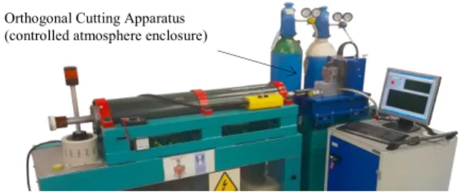
Fig 1. presents the set-up that was developed, which uses a linear electromagnetic actuator to impose controlled velocity and energy to the kinematics transmission systems. Cutting
forces are monitored by a three-dimensional piezoelectric dynamometer enclosed in a chamber that was specially designed to control the surrounding medium of the cutting tests. In the present work, the relative position between tool and workpiece was considered as a major contribution to the understanding of the contact mechanics at the chip-tool interface. Thus, a high accuracy linear inductive transducer was developed to overcome difficulties related with high speed and harsh acceleration during experimental tests [19].
Fig. 1. Metal cutting apparatus: Custom-built kinematics appliances based on a linear electromagnetic actuator while cutting tools and specimens remain
inside a controlled atmosphere enclosure.
2.2. Materials and specimens
Triangular uncoated carbide inserts TCMW 16T308 H13A were used. Flat top chip-breaker with null rake angle and a clearance angle of 7º ensure adequate tool geometry for direct measurement of both normal force and tangential force on the rake face. Clearance surface was polished to a very smooth surface to minimize its interaction with the machined surface. To achieve and recondition a nearly perfect surface, lapping and polishing techniques were used, resorting to diamond grits ranging from 5 to 0.5 µm applied on a lap plate. The inserts were then worked across the plate at very low pressure and speed until a scratchless mirror-like surface was achieved. This procedure assures an adequate roughness and texture of both rake and clearance faces, and cutting-edge sharpness. Cutting-edge radius was maintained below 1 µm (Fig. 2) and the ratio of the uncut chip thickness to the cutting-edge radius was adequate to neglect the influence of the ploughing and rubbing mechanism on the cutting force values.
The choice of workpiece material is crucial to emphasize different phenomena that occur during chip flow in favour of the comprehensive analysis on friction mechanics at the tool– chip interface. Pure metals were chosen since their less complex chemical reaction products, under the influence of active surrounding medium, reduce experimental data dispersion. Specimens were manufactured from pure metals (Zinc 99.99%, Tin 99.999%, Aluminium 99.999% and electrolytic Copper 99.999%) and unalloyed metals (Titanium 99.6% and Lead 99.5%), which have been previously strain-hardened. The cut specimens were faced to a rectangular cuboid with a length/width/thickness of 9/7/2mm, respectively. Since the oxidation mechanism is favored by high exposure times to the surrounding atmosphere, typical of low cutting speeds, and also high surface temperatures, typical of high cutting velocities, a compromise was attained and a constant cutting velocity (Vc) of 500 mm/min of the linear guide was used for all experimental tests.
Orthogonal Cutting Apparatus (controlled atmosphere enclosure)
2.3. Experimental work plan
The tribological experiments were performed under orthogonal cutting conditions; the ratio between the uncut chip thickness and the specimen width was kept below 1/80 to ensure plane strain conditions and uncut chip thickness was set constant to 25 µm to focus exclusively on the influence of surface roughness and oxygen concentration on the friction coefficient. Fig. 2 shows two different conditions of the cutting inserts: (i) modified inserts combining a polished clearance face and two rough rake face conditions, as supplied (Ra 0.25 µm) and roughly polished (Ra 0.1 µm) and (ii) modified inserts that had both clearance and rake faced completely polished (Ra less than 0.015 µm) and a sharp cutting edge (cutting radius less than 1µm). The first set of inserts was used to support a comprehensive analysis about surface roughness influence on friction coefficient whereas the second set of inserts differs from the ones found in traditional cutting tools since orthogonal cutting itself is not a tribological test and particular conditions must be assured in order to guarantee a comprehensive study on metal cutting tribology.
The cutting medium, which plays an important role in defining the chemical reaction nature, was set to control oxidation rates during the cutting tests: (i) inert medium of Argon and (ii) active medium of Oxygen (21% and 100%). The active gas medium surrounding the detach gap between tool and work material promotes oxidation of the newly formed chip during cutting, favoring the level of permeability. The utilization of a gaseous atmosphere also allows the observation of the chip flow during the cutting tests through a clear gas medium. The interaction of the medium on the chip detachment has been limited by a gas flow meter (5 L/min).
Fig. 2. Cutting tools: (a) Polished clearance surface while preserving stock rake surface; (b) Polished insert with sharpened cutting-edges.
3. Results and discussion
3.1. Rake surface condition
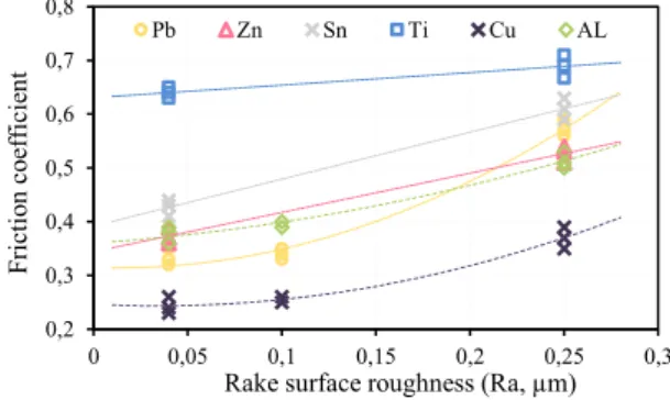
Surface roughness of cutting tool is a major parameter on metal cutting tribology. As previously mentioned, clearance surface contribution on the cutting tests can mislead friction calculations, particularly in the case of rough clearance surfaces since tool asperities anchor in the machined surface promoting an increase of the cutting forces followed by an apparent friction coefficient reduction. Thus, clearance surfaces must be as polished as possible to allow realistic estimates of the friction coefficient. Fig. 3 shows the evolution of the friction coefficient in the contact interface (steady-state regime) as a function of the average roughness of the rake surface. An inert medium of Argon was used to inhibit oxidation phenomena, thus avoiding its contribution to the friction measurements. As seen, surface roughness has a
significant influence on friction coefficient (e.g. an increase of 80% can be observed in Pb).
Fig. 3 presents fitting lines and their extrapolations, which do not pass through the origin. Rather, a positive intercept is observed. This intercept is known experimentally and is usually explained in terms of ploughing and rubbing action, but this unwanted geometric contribution can be minimized using sharp-angled tools and well-polished surfaces (both clearance and rake surfaces). Even in this condition, a positive interception can be found and experimental measurements of friction can be taken as an unequivocal indicator of adhesion (µ µadhesion). As surface roughness increases, a more pronounced interaction between the hard asperities of rake surface and the freshly formed underside of the chip is noted. A deep interlocking of asperities promotes additional sliding resistance, rising the friction force and, therefore, the friction coefficient for rougher tools. However, the asperity interlocking mechanism only becomes effective if the tips of the tool asperities are able to indent the work material. Titanium seems to be less sensitive to this mechanism possibly due to its higher mechanical resistance to penetration.
Fig. 3. Friction coefficient for different test material as a function of the rake surface roughness. Test parameters: Polished clearance surface (Ra=0.01µm),
t0=0.025mm, w=2mm, Vc=500mm/min, cutting in Argon).
3.2.Friction of non-oxidized metallic surfaces
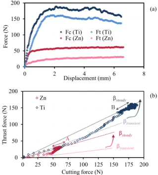
The cutting and thrust forces measured from transient beginning to the steady-state cutting regime can be analysed in Fig. 4a for both Zinc and Titanium. Polished cutting inserts were used and the cutting tests were conducted at room atmosphere. When the cutting tool first contacts the work material, compression occurs. As the cutting action progresses, stress increases up to the moment when rupture occurs causing material separation from the uncut portion and the metal begins flowing along the rake surface - similar to the plastic indentation process. The contact pressure acting on the rake surface is mainly related with the material flow stress whereas the frictional stress is determined by the characteristics of the contact interface. Fig. 4b shows a linear increase in thrust force (Ft) as function of the cutting force (Fc). Furthermore, three different slopes can be identified, corresponding to well-defined regions: (i) a leftmost region (Fc < 45 N and 100 N for Zinc and Titanium, respectively) where the friction angle is nearly constant (βtransient = 14º for Zinc and 28º for Titanium); (ii) a rightmost region where the cutting force reaches its maximum value (Fc > 60 N and 180 N for Zinc and Titanium, respectively) and friction angle is
0,2 0,3 0,4 0,5 0,6 0,7 0,8 0 0,05 0,1 0,15 0,2 0,25 0,3 Fr ic tio n c oe ffic ie nt
Rake surface roughness (Ra, µm)
Pb Zn Sn Ti Cu AL Cutting edge Rake face Clearance face 10m (b) (a)
A. Gregorio et al. / Procedia CIRP 82 (2019) 136–141 139
4 Author name / Procedia CIRP 00 (2019) 000–000
constant (βsteady = 33º for Zinc and 56º for Titanium) even when fluctuation of he cutting force is observed (point-cloud); and, (iii) a region bounded by the previously described ones, where the friction angle value progressively increases from its lowest to its highest, evidencing intimate contact between the chip and the tool. It is also observed that the evolution of the thrust force Ft against the cutting force Fc slightly decreases at the beginning of the steady-state regime (Fig. 4b, A and B, for Zinc and Titanium, respectively).
Two points can be outlined from Fig.4: (i) the transient condition seems consistent with the progressive replacement of the oxidized layer by a newly generated metallic surface in the contact interface (please see Fig.8); and (ii) the friction angle increases from its lowest value at the initial transient conditions to its highest, reaching a value of 56º for Ti (33º for Zn), far higher values than what is commonly observed in metal forming processes. In the case of Titanium, friction values are significantly higher than the ones measured for other test materials, for every test condition. In fact, it is well known that Ti reacts with WC, promoting Cobalt melts to adhere to the rake surface and also Carbon diffusion from WC thus forming TiC at the contact interface [20]. At the beginning of the cutting process, the workpiece surface presents a thin film of metallic oxide. As cutting process progresses and rupture occurs, the natural thin oxide film, present in the workpiece, expands, breaks and fragments and a real metallic surface is generated at the underside of the chip. Such conditions become propitious for higher diffusion rate of Carbon from WC to form TiC and for the formation of Co melts, which increase during the cutting of Ti, causing strong chemical adhesion thus leading to high friction values.
Fig. 5 shows the transient tribological conditions whereby friction coefficient increases sharply at the beginning of the cutting test (A in Fig. 5) and remains almost constant throughout subsequent steady-state cutting regime (B in Fig. 5). It is worth noticing that experimental data trend does not intersect the origin, being the positive interception the adhesion for the material pair tool-oxidized metallic surface (workpiece). Further on, friction coefficient increases asymptotically up to a maximum value (µ = 0.85 for Ti and 0.5 for Zn) for a tool displacement much higher than the uncut chip thickness, which seems to illustrate that, although chip separation is well established, additional chip flow over the rake face is required to sweep up contaminants such as lubricants or oxide debris. In what follows, the presence of oxides appears to promote lower friction and reduced metal-metal contact. The high displacement required does not seem consistent solely with the oxide removal mechanism, raising questions about the existence of neglected contributions in the formulation of metal cutting tribology.
3.3. Oxidation effects on the friction coefficient
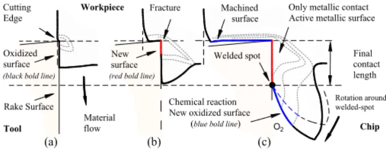
The formation of non-oxidized metallic surfaces near the cutting-edge was discussed in previous section. Yet, it is still unclear how and where the oxidation of these surfaces occurs, and also, how the oxides formation can affect friction. At the moment of chip detachment, the newly generated and chemically active underside of the chip becomes vulnerable to
the surrounding medium, which can be of two types: (i) active gas/liquid shield, or (ii) inert gas/liquid shield. In the case of an inert gaseous shield, such as a Nitrogen (N) or Argon (Ar) rich surrounding medium, chip oxidation occurs only after material removal, being friction left undisturbed. However, when the removal of material takes place in the presence of active surrounding mediums, such as those rich in Oxygen, it results in the formation of oxide films at the underside of the chip. These chemical reactions occur under pressure, promoting the formation of cold pressure-welded spots over the rake surface of the cutting tool, as evidenced by Fig.6, which shows that the position density of pressure welded spots increases with Oxygen concentration. The oxide films are then smeared over the rake surface with two commonly combined contributions over the friction mechanism: (i) chip and tool are bonded together by several welded joints and (ii) oxide welded spots left over the rake face promote an artificial roughness of the cutting tool. The formation and deposition of these oxides is not confined to the rake surface of the tool, they can also stack on top of each other increasing the thickness of this deposit, which must be taken into consideration due to its relevant impact on the friction in the tool-chip contact interface.
Fig. 4. Tribological cutting tests for Titanium (Ti) and Zinc (Zn): (a) Cutting and thrust forces as a function of the tool displacement; (b) Relative evolution
between the cutting and thrust forces. Test parameters: t0=0.025m, Vc=500mm/min, cutting in room atmosphere.
Fig. 7 shows the dry cut of Tin under two different gas shields. When an inert shield of Argon is used (Fig. 7a) the chip is allowed to curl naturally – typical of low friction, whereas the exposure to an active Oxygen-rich atmosphere (Fig. 7b) causes the chip radius to greatly increase – typical of high friction. As a matter of fact, in the case of a 100% Oxygen atmosphere, the Tin chips flow parallel to the rake face. The natural curling kinematics is thus opposed by a secondary rotation mechanism, as presented in Fig 8c. The total friction force that opposes the sliding movement of the chip in relation to the cutting tool is a result not only of the
0 50 100 150 200 0 2 4 6 8 Fo rc e (N ) Displacement (mm) Fc (Ti) Ft (Ti) Fc (Zn) Ft (Zn) 0 50 100 150 200 0 25 50 75 100 125 150 175 200 Th ru st fo rc e (N ) Cutting force (N) Zn Ti βtransient βsteady βtransient βsteady B A (a) (b)
traditional metal forming tribology, but also of an additional contribution from the shear force required to dismantle the welded junction and to surpass pure interlocking with the oxide asperities.
Fig. 5. Transient tribological conditions for Titanium (Ti) and Zinc (Zn) as function of tool displacement. Test parameters: t0=0.025m, Vc=500mm/min,
cutting in room atmosphere.
Fig. 6. Direct observation of the tool’s rake surface after cutting Sn under different gas shields: (a) Argon; (b) Room ambient; (c) Oxygen
Fig. 7. Direct observation of the chip curling of Tin (Sn): (a) Inert gas shield of Argon; (b) Active gas shield of Oxygen. Test parameters: polished tool,
t0=0.025mm, w=2mm, Vc=500mm/min.
Oxidized
surface contactFinal
length Chemical reaction
New oxidized surface (blue bold line)
Welded spot New
surface
(black bold line)
Tool Materialflow O2 Chip
(a)
Fracture Cutting
Edge Workpiece Only metallic contactActive metallic surface
Rake Surface
Machined surface
(b) (c)
(red bold line)
Rotation around welded-spot
Fig. 8. Schematic description of the transient tribological conditions: (a) Initial contact of the cutting tool on the workpiece’s oxidized surface; (b) Transition from the oxidized surface to the just-formed metallic surface at the
tip of the tool; (c) Contribution of the chemical oxidation to the friction mechanism allowing to reach steady-state conditions at the contact interface.
3.4. Oxygen concentration
To address the influence of Oxygen concentration on the friction coefficient, experimental tests were carried out on pure metals, using a polished insert (both rake and clearance faces), for concentrations of 0, 21 and 100% in volume of the surrounding medium. Fig. 9 shows two distinct friction signatures in the measurements during steady-state regime: (i) friction coefficient increases and (ii) friction coefficient decreases with Oxygen concentration, depending on the test material. These signatures, observed during steady-state
regime indicate that the chemical changes in the exposed metallic surface persist during chip flow with direct impact on the friction coefficient. This can be attributed to the formation of oxide films on the underside of the chip, which is promoted by chemical reactions of the Oxygen with the pure metals. In fact, the mechanics of chip formation are very responsive to small changes in the tribological condition due to its unconfined plastic nature.
As previously discussed, both contact length and chip curl gradually increase from the transient beginning of cutting to the state regime of the chip flow. Moreover, steady-state conditions demand a compromise between the energies involved in plastic and frictional work. As friction grows, the cutting geometry is redefined in order to maintain a stable equilibrium. Frictional work and the contact length are directly proportional and, therefore, needs to be balanced by the plastic work related to the plastic curling of the chip. In the case of a continuous increase of both contact length and chip radius, spreading oxides over a wide area of the rake surface, equilibrium state will not be reached and chips progressively pile up over the rake surface to failure.
The evolution of friction coefficient with the concentration of Oxygen in the surrounding medium is controlled by the chemical affinity between the metallic element and Oxygen. For instance, in the case of Copper, the presence of high Oxygen concentration in the cutting fluid promotes an increase of the friction coefficient, which seems to indicate that the cutting of Copper alloys using, e.g. Oxygen-rich soluble oils can be inappropriate. The use of straight oils instead may be preferable.
Fig. 9. Friction coefficient as a function of Oxygen concentration in the surrounding medium for several materials. Test parameters: Polished tool,
t0=0.025mm, w=2mm, Vc=500mm/min.
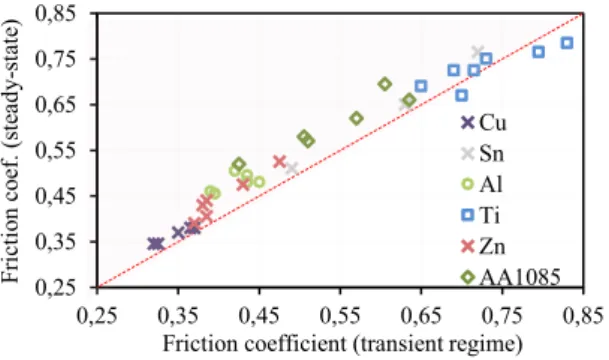
3.5. Transient to steady-state friction
Fig. 10 allows to conclude that friction coefficient presents a transient regime as chip detaches from the tool until chip curling stabilizes when steady-state conditions are attained; since friction coefficient at steady-state conditions crosses the symmetry line (red dashed line). The typical overall increase in friction coefficient ranges from 5% to 15%, being these results verified under different metal cutting conditions with similar conclusions. This is due to the persistent compression that chip is subjected to, causing a progressive pile-up mechanism and increase in contact length. The deposition of these oxide films over the rake face progressively forms a chip-breaker until steady-state regime is established.
0 0,2 0,4 0,6 0,8 1 0 1 2 3 4 5 6 7 8 Fr ic tio n c oe ffic ie nt Displacement (mm) Zn Ti A B 0,2 0,3 0,4 0,5 0,6 0,7 0,8 0 20 40 60 80 100 Fri ct io n c oe ffi ci en t Oxygen concentration (%) Al Cu Pb Sn Ti Zn
Rake face Pressure-welded spots
(a) (b) (c)
A. Gregorio et al. / Procedia CIRP 82 (2019) 136–141 141
6 Author name / Procedia CIRP 00 (2019) 000–000
4. Conclusions
The present study in metal cutting tribology focused on the formation of new metal surfaces at the tool-tip and addresses three main issues, related to: (i) surface roughness of the cutting tool, (ii) formation of non-oxidized metallic surfaces and sliding on the rake surface and (iii) chemical oxidation at the point where chip detaches from the tool. The effect of these phenomena on friction coefficient is then thoroughly analysed. The results obtained from experimental tests show that significant variation in both friction coefficient and cutting geometry are promoted by the Oxygen concentration in the surrounding medium, evidencing that oxide films, formed on a recently cut surface, have an expressive influence on the metal cutting tribology. The presence of oxides may lead to an increase or reduction of the friction coefficient, depending on the test material, but also on the gaseous shield. The formation of new chemical active surfaces and the notion of pressure-welded spots were also accounted in order to provide a better insight on why cutting in the presence of different Oxygen concentrations influences the metal cutting performance. Experimental observations show that friction coefficient is not a constant value, but a function of the process parameters instead, and varies as the chip progresses along the rake surface. Friction has a greater impact on the free plastic flow of metal cutting with measured friction coefficients higher (from 0.3 to over 1) than in metal forming processes (typically ranging from 0.1 to 0.4).
Fig. 10. Evolution of the friction coefficient from transient regime to steady-state conditions for all the test materials and surrounding medium types. Test
parameters: Polished tool, t0=0.025mm, w=2mm, Vc=500 mm/min.
It was demonstrated that the presence of different Oxygen concentrations in the surrounding medium significantly affects the metal cutting tribology. In addition, the understanding of the oxidation mechanism is crucial for a complete comprehension of chip formation mechanics. Such outcomes indicate that the oxidation mechanism is also of great importance for theoretical estimates of cutting forces and energy consumption. Thus, further work should concern on establishing a theoretical foundation for alternative tribological constitutive models comprising the effect of the non-oxidized metallic surfaces and the oxidation phenomena on the chip formation mechanism. It is well known in fact, that traditional finite element software employed for numerical simulations of cutting processes do not provide friction models that include oxidation phenomena. The integration of the oxidation mechanism in numerical models,
paired with the development of new tribological techniques for macroscopic calibration of both the friction coefficient of truly metallic surfaces and the shear stress of pressure-welded spots, is expected to allow a more accurately modelling of metal cutting processes.
Acknowledgements
This work was supported by FCT, through IDMEC, under LAETA, project UID/EMS/50022/2019.
References
[1] Zorev NN. Results of work in the field of the mechanics of the metal cutting process. Proc Inst Mech Eng 1958:255.
[2] De Chiffre L. Mechanics of metal cutting and cutting fluid action. Int J Machine Tool Design and Research 1977;17(4):225-234.
[3] Shaw MC. Metal cutting principles. Oxford Series on Advanced Manufacturing; 1984.
[4] Zemzemi F, Rech J, Salem BBW, Kapsa P, Dogui A. Development of a friction model for the tool–chip–workpiece interface during dry machining of AISI 4142 steel with TiN coated carbide cutting tools. Int J Machining and Machinability of Materials 2007;2:361-367.
[5] Schey JA. Tribology in metalworking: friction, lubrication and wear. American Socie-ty for Metals: Materials Park 1983.
[6] Horne JG, Doyle ED, Tabor D. Direct observation of chip-tool interface in metal cutting. Proc Fifth North American Metalworking Research, SME, Amherst MA 1977:237-241.
[7] Doyle ED, Horne JG, Tabor D. Frictional interactions between chip and rake face in continuous chip formation. Proc R Society A 1979;366:173-187.
[8] Madhavan V, Chandrasekar S, Farris TN. Direct observations of the chip-tool interface in the low speed cutting of pure metals. J Trib 2002;124:617.
[9] Williams JA, Tabor D. The role of lubricants in machining. Wear 1977;43:275-292.
[10] Pepper S. Effect of interfacial species on shear strength of metal-sapphire contacts. J Applied Physics 1979; 50:8062-8066.
[11] Lorentzon J, Järvstråt N, Josefson BL. Modelling chip formation of alloy 718. J Materials Processing Technology 2009;10:4645-4653
[12] Zhang S, Guo YB. An experimental and analytical analysis on chip morphology, phase transformation, oxidation, and their relationships in finish hard milling. Int J Machine Tools and Manufacture 2009;49(11):805-813.
[13] Brinksmeier E, Lucca DA, Walter A. Chemical aspects of machining processes. CIRP Annals Manuf Technology 2004;53:685-699.
[14] Batra IP, Kleinman L. Chemisorption of oxygen on aluminum surfaces. J Electron Spectroscopy and Related Phenomena 1984;33:175-241. [15] Zhukovskii YF, Jacobs PWM, Causá M. On the mechanism of the
interaction between oxygen and close-packed single-crystal aluminum surfaces. J Physics and Chemistry of Solids 2003;64(8):1317-1331. [16] Svahn F, Kassaman-Rudolphi A, Wallen E. The influence of surface
roughness on friction and wear of machine element coatings. Wear 2003;254:1092-1098.
[17] Sedlacek M, Podgornik B, Vizintin J. Influence of surface preparation on roughness parameters, friction and wear. Wear 2009;266:482-487. [18] Cristino VAM, Rosa PAR, Martins PAF. Cutting under active and inert
gas shields: a contribution to the mechanics of chip flow. Int J Machine Tools & Manufacture 2010;50:892-900.
[19] Rosa PAR., Gregorio AVL, Davim JP. The role of oxygen in orthogonal machining of metals. In: Davim JP, editor. Measurement in Machining and Tribology. Springer; 2019. p. 49-88.
[20] Sadik M, Latterman M, Garcia J. Specific carbide substrate design to enhance tool performance in machining of Ti5553. Procedia CIRP 2018; 77:598-601. 0,25 0,35 0,45 0,55 0,65 0,75 0,85 0,25 0,35 0,45 0,55 0,65 0,75 0,85 Fr ict io n co ef . ( st ead y-st at e)
Friction coefficient (transient regime) Cu Sn Al Ti Zn AA1085