Science Arts & Métiers (SAM)
is an open access repository that collects the work of Arts et Métiers Institute of
Technology researchers and makes it freely available over the web where possible.
This is an author-deposited version published in: https://sam.ensam.eu Handle ID: .http://hdl.handle.net/10985/11397
To cite this version :
Razvan CHITIC, Richard BEAREE, Betty LEMAIRE-SEMAIL - Industrial equipment for Powder transportation using piezoelectric “friction control” method - In: ACTUATORS 2012, Allemagne, 2012-06 - Actuators - 2012
Any correspondence concerning this service should be sent to the repository Administrator : archiveouverte@ensam.eu
Industrial equipment for Powder transportation using
piezoelectric “friction control” method
R. Chitic1, 2,4, R. Bearee1,3, F. Giraud1,2, B. Lemaire-Semail1,2, M. Favre4, P. Tierce4, J. Jehanno5
1
University Lille 1, F-59000 France,
2
Laboratoire d’Electrotechnique et d’Electronique de Puissance de Lille F-59000, France
3
Ecole Nationale des Arts et Métiers Paris tech Bd Louis XIV Lille France
4
SinapTec, Lezennes, France
5
AREVA, France
Abstract:
This paper presents a new powder transportation system that uses a high frequency flexural stationary wave coupled with a low frequency horizontal displacement of a beam to produce the transport of the powder. The ultrasonic wave is produced with the help of piezoelectric cells glued under the beam and is used to decrease the friction coefficient between the powder and the beam surface.
Keywords: powder transportation, ultrasonic vibration, friction control
Introduction
Powder transportation is sometimes a delicate stage of an industrial process, although it gives the final product no added value: in general, it is expected that the transported powder does not segregate nor suffers chemical alteration and that no loss of material is observed. Today many powder transport systems exist but they suffer from a significant number of defects to be corrected: conveyor belts or vibratory conveyor are often noisy mechanical systems, requiring a massive energy consumption and costly maintenance due to their moving parts.
To cope with those problems, Ultrasonic Powder Transport Systems use ultrasonic vibrations to transport powder. For example, [1] [2] propagates an ultrasonic progressive wave into a specific pipe material with appropriate absorption properties. They obtained a simple device with no moving part which can transport powder with good performances. However, the pipe material needs to absorb the reflective wave, dissipating the electrical power into heat.
In this paper, we use a high frequency flexural stationary wave coupled with a low frequency horizontal displacement. Our goal is to decrease the amplitude of horizontal displacement compared to classical technologies, while ultrasonic vibrations are imposed with a good efficiency because they are stationary.
In the first section, we describe the friction reduction principle which is used to propel the powder, then a description of the test set-up is given, while we present in the final section the experimental results.
Friction control principle
A beam is submitted to a sinusoidal low frequency movement (LFM) in the direction of the excited transport.
Fig. 1. Illustration of the friction control principle
In order to create powder transportation, a dissymmetry in contact condition between the powder and the beam has to be introduced
synchronized on the LFM. Such a dissymmetry is obtained by decreasing the friction coefficient. This is achieved if a high frequency vibration (HFV) at 20kHz is produced [3] [4]. Its amplitude is modulated by a signal named (MS), synchronized with the LFM. The synchronization principle consists in using HFV only when the friction coefficient has to be decreased. For transportation creation, the reaction force transmitted to the powder by the transportation system (for instance a beam) has to be only directed according to the desired direction of transportation. Figure 1 presents the friction control principle. Hence, when the LFM acceleration is opposite to the desired direction, the HFV is introduced to reduce the contact coefficient with the transportation device. When the HFV is used, one can assumed that the powder motion is still in the expected direction due to inertial effect.
Experimental set-up
Figure 2 depicts the tests bench, which will be used for the experimental investigations. A shaped beam is used to eliminate the possibility that the powder will fall off the plate [5]. A linear motor is used to create the LFM of the beam. In addition, we glued piezoelectric cells under the beam to create the HFV. One can note that the location of the piezoelectric cells is optimized using modal analysis to correspond to the maximum amplitude locations of the flexural vibrational mode excited by HFV.
Fig. 2. Tests set-up overview
The elastic supports of the beam needs to be positioned in precise locations determined using the modal analysis of the beam. They need to be mounted on the nodes position of the HF flexural wave, to avoid the perturbation of flexural deformation [6]. The voltage supplied to the ceramics is synchronized with the beam’s position, which is measured by a position sensor. Closed loop control is achieved by a computer embedding DSpace controller.
The test bench was designed to be easily inclined for helping the powder transportation.
Results
A series of preliminary tests have been conducted. They consist in using only the high frequency flexural stationary wave in order to establish the influence of the ultrasonic vibration on the friction reduction between the powder and the beam. During the test we changed the quality surface of the beam by adding a layer of tape with different thickness h: tape #1 – h=0.05mm and tape #2 – h=0.12mm. 0 0.2 0.4 0.6 0 400 800 1200
High frequency amplitude p-p (nm)
F lo w r a te ( g /s )
Fig. 3. Flow rate in function of HF amplitude for a corundum powder with a 15° inclination of the system and Tape #1 quality of the beam surface.
In the figure 3, we show the evolution of the flow rate as a function of the HFV amplitude. Such a curve is generic for all tested powder. It shows that if there is no vibration, no powder transportation is obtained, which is normal because there is no dissymmetry in contact conditions then.
On the same figure, we can see that at least 400nm p-p is required to produce powder transportation, and that 1000nm p-p produces good transport conditions.
Figure 4 gives the evolution of the flow rate as a function of HFV amplitude for different qualities of the beam surface. These trials have been done with a
15° inclination of the system. As we can see, higher tape thickness produces lower flow rate.
-0.2 0 0.2 0.4 0.6 0.8 0 500 1000 1500 2000 HF amplitude p-p (nm) F lo w r a te ( g /s ) Tape #1 Stainless steel Tape #2
Fig. 4. Flow rate in function of HF amplitude for different beam surface using a corundum powder.
Now we present the results obtained using HFV synchronized with the LF displacement. In figure 5 we can see the curves for the flow rate in function of the LF displacement with different inclinations α of the system. The HFV amplitude is kept constant for the two inclinations but not equal: we have 830nm peak amplitude for α=15° and 530nm peak amplitude for α=0°. The flow rate is more important for a 15° inclination of the system, because the transversal
component of the weight force is added to the force displacement produced by the LF movement of the beam. 0 0.3 0.6 0.9 1.2 0 200 400 600 800 1000 LF displacement p-p (µm) F lo w r a te ( g /s ) α=15° α=0°
Fig. 5. Flow rate in function of LF displacement for different inclination of the system using a corundum powder. Stainless steel quality of the beam surface.
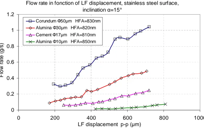
In the figure 6, we plotted the curves of the flow rates for different types of powders in function of the horizontal displacement and for constant HFV amplitude. These tests have been done considering a 15° constant inclination of the system. As we can see the arrangement of the curves depend on the morphological characteristics of the powders (in ex. average diameter of the particles noted Φ).
Flow rate in fonction of LF displacement, stainless steel surface,
inclination
α
=15°
0
0.2
0.4
0.6
0.8
1
1.2
0
200
400
600
800
1000
LF displacement p-p (µm)
F
lo
w
r
a
te
(
g
/s
)
Corundum Φ50µm HFA=830nm Alumina Φ30µm HFA=820nm Cement Φ17µm HFA=810nm Alumina Φ10µm HFA=850nmConclusion
This paper presents a new powder transportation system. It consists in a beam which is excited in a low frequency movement. A dissymmetry of the contact conditions according to the low frequency displacement is produced by creating flexural vibration of the beam. We found that ultrasonic vibrations with amplitude synchronized with the beam position could help to propagate the powder.
References
[1] M. Mracek et J. Wallaschek, « A system for powder transport based on piezoelectrically excited ultrasonic progressive waves »,
Materials Chemistry and Physics, vol. 90, no. 2– 3, p. 378–380, avr. 2005.
[2] U. Kühne et U. Fritsching, « Dosage of highly disperse powders by ultrasound agitated tube modules », Powder Technology, vol. 155, no. 2, p. 117–124, juill. 2005.
[3] M. Biet, F. Giraud, et B. Lemaire-Semail, « Squeeze film effect for the design of an ultrasonic tactile plate », IEEE Trans. Ultrason.,
Ferroelect., Freq. Contr., vol. 57, no. 12, p. 2678–2688, déc. 2007.
[4] E. C. Chubb, J. E. Colgate, et M. A. Peshkin, « ShiverPad: A device capable of controlling shear force on a bare finger », in EuroHaptics
conference, 2009 and Symposium on Haptic Interfaces for Virtual Environment and Teleoperator Systems, World Haptics 2009, Third Joint, Salt Lake City, UT, USA, 2009, p.
18–23.
[5] Y. Hashimoto, Y. Koike, et S. Ueha, « Transporting objects without contact using flexural traveling waves », J. Acoust. Soc. Am., vol. 103, no. 6, p. 3230–3233, juin 1998.
[6] W. Szlabowicz, « Contribution au dimensionnement et à la réalisation d’actionneur piézoélectrique à rotation de mode fort couple pour applications aéronautiques », PhD thesis, INPT - ENSEEIHT, Toulouse, 2006.