MÉMOIRE PRÉSENTÉ À
L'UNIVERSITÉ DU QUÉBEC À CHICOUTIMI COMME EXIGENCE PARTIELLE
DE LA MAÎTRISE EN INGÉNIERIE
PAR
Marwan Hamed
Paramètres de fraisage pour les alliages coulées Al-Cu et Al-Si
Quebec, Canada © [Marwan Hamed], [2019]
THESIS PRESENTED TO
UNIVERSITY OF QUEBEC AT CHICOUTIMI
IN PARTIAL FULFILLMENT OF THE REQUIREMENT FOR THE DEGREE OF MASTER IN ENGINEERING
BY
Marwan Hamed
Milling Parameters For Al-Cu and Al-Si Cast Alloys
Quebec, Canada © [Marwan Hamed], [2019]
Dedicated to my parents,
my sister Rana, my cousin 7iha and my best friend Marwan Sallam… #19
I
ACKNOWLEDGMENT
First and foremost, I would like to thank God Almighty for giving me the strength, knowledge, ability and opportunity to undertake this research study and to persevere and complete it satisfactorily. Without his blessings, this achievement would not have been possible.
I would like to express my sincere gratitude to my supervisor, Prof. Fawzy Hosny Samuel, Professor at Université du Québec à Chicoutimi (Canada) for his guidance, advice and support throughout my research work; it has been an honor to be his student. I would also like to thank my co-supervisor, Prof. Agnes M. Samuel, Research Professor at Université du Québec à Chicoutimi (Canada) for her continuous guidance, support, and helpful suggestions in improving the quality of my thesis. Without their continuous guidance and support it would have been impossible to complete my master’s degree.
Financial support received from General Motors Powertrain Group (USA), Natural Sciences and Engineering Research Council of Canada (NSERC), and Corporativo Nemak (Mexico) is gratefully acknowledged. It is a pleasure to thank all those who have contributed in completion of this study: Herbert W. Doty Technical Specialist Materials Technology in General Motor and Salvador Valtierra Gallardo Process Technology Manager in Nemak , I would like to thank my friend and colleague , Eng. Hussien Barakat in TAMLA Group for his help at various stages of my work without him it would be difficult.
II I would like to Thank all my friends for not squashing my dreams, but rather encouraging them. Thank you for empowering me, helping me know that I was on track, right where I needed to be. Thank you all for helping me to feel able, in balance and hopeful. Thank you for listening to me and brainstorm my ideas.
Lastly but most importantly My family is everything. I am what I am thanks to my mother, my father and my sister I want to thank my parents and share the love and care that you two have given me in all my life. You are the most perfect parents in this world, the biggest blessing for a child is his parents. I feel lucky all the time for having such amazing parents like you! Love and support of parents can get their son anywhere and everywhere in life. Thank you, mom and dad, for always supporting me.
I would like to take the chance and express my deep love toward my joyful sister Rana who has passed through lots of ups and downs through her life and still have such a pure heart , thank you for inspiring and supporting me and wishing me all the best , thank you my sister I wish you to be strong and wise.
I would like to express my thanks and appreciation to my mentor Mohamed Abdelaziz. You are a wonderful teacher, leader, and friend. You are everything one could look for in a good mentor. Thank you for guiding me on the right path. I will always be thankful to you and I wish you great success in your life.
Thank you all…..
Marwan Hamed July #19
III
RÉSUMÉ
La présente étude a été réalisée dans le but d’étudier les caractéristiques d'usinabilité, c'est-à-dire les caractéristiques d'usinage d'un alliage Al-6%Cu-0,7%Si (dans les conditions de vieillissement T5 et T7), et de comparer ces caractéristiques à celles bien définie de l’alliage B319.0 (brut de coulé et traité T7) et A356.0 (brut de coulé et traité T6). Le surfaçage a été effectué sur 15 blocs préparés à partir de chaque alliage en utilisant de nouvelles plaquettes en carbure pour une distance d'usinage d'environ 120m. Trente-cinq blocs (12 x 7 po x 1,5 po) ont été utilisés. Le fraisage a été effectué à l'aide d'une machine à grande vitesse 5 axes à commande numérique Huron KX Five. L'expérience comprenait la machine à commande numérique, les blocs à usiner, un dynamomètre de table avec des capteurs piézoélectriques chargés de détecter et de mesurer les forces de coupe, un amplificateur de signal et une unité de conversion analogique-numérique. Des plaquettes de coupe neuves et usées ont été utilisées pour chaque groupe d'alliages. Treize couches de matériaux ont été retirées de chaque bloc, chaque couche étant composée de 10 chemins et la profondeur de coupe étant de 1,35 mm.
Les résultats obtenus avec de nouvelles plaquettes ont montré que le traitement thermique appliqué n’affectait pas les forces de coupe des alliages à base d’Al-Cu. La présence de Cu dans l'alliage B319.0 a neutralisé dans une certaine mesure l'effet néfaste des particules de Si dur. Les forces de coupe maximales ont été obtenues lors de l’usinage de l’alliage A356.0 traité au T6, en raison de la présence d’une densité élevée de particules de silicium eutectiques dures (environ 41495 particules/mm2) ainsi que d’une précipitation dense de particules ultrafines de Mg2Si. Ainsi, les 6% de Cu dans l'alliage à base d'Al-Cu peuvent être considérés comme un autolubrifiant, conduisant à des surfaces de finition beaucoup plus lisses par rapport à celles présentées par les alliages B319.0 et A356.0. Des observations similaires ont été rapportées sur l’usure des outils de forage. En outre, après une distance d'usinage de 120 m, de minuscules bavures ont été collées sur les bords extérieurs de la pièce à usiner, alors que dans le cas de l'alliage A356.0, elles étaient séparées du bloc.
Les inserts émoussés ont été obtenus en passant les inserts neuf sur un bloc de fonte blanche afin de réduire la netteté des nouveaux inserts en carbure. Ce processus a entraîné de graves dommages à l'insert et la formation de cavités profondes. La forme des plaquettes mates et les caractéristiques de coupe varient d'une plaquette à l'autre et il est donc difficile d'obtenir des résultats reproductibles. En raison de la mauvaise forme des plaquettes mates, les efforts de coupe nécessaires pour usiner une distance de 14 m étaient 40 à 50% plus élevés que ceux requis avec les nouvelles plaquettes pour usiner une distance de coupe de 120 m. Le profil de rugosité de surface avec des outils émoussés était presque le double de celui obtenu avec de nouvelles plaquettes. Cependant, les signaux étaient beaucoup plus
IV larges dans le premier cas avec moins de pics. En raison des graves irrégularités des bords des outils émoussés, ni la composition de l'alliage ni le traitement thermique ne sont pertinents. La finition de surface de tous les alliages était caractérisée par la présence de fissures et de trous peu profonds. Les contraintes résiduelles ont varié sur la largeur du bloc usiné. Toutes les contraintes étaient de type tension par rapport au type compression dans les épaules non usinées. En raison des forces appliquées élevées requises lors de l'utilisation d'inserts émoussés, les contraintes résiduelles résultantes étaient presque le double de celles générées par les nouveaux inserts malgré la grande différence de distance d'usinage. En raison de l’utilisation d’une douche de liquide de refroidissement, les copeaux étaient brillants et ne présentaient aucun signe de brûlure. Dans tous les cas, les fraises étaient séparées des pièces à traiter (fraises positives).
V
ABSTRACT
The present study was carried out to study the machinability i.e. milling characteristics of an Al-6%Cu-0.7%Si alloy (in the as-cast, T5 and T7 aging conditions) and compare these characteristics to those of well-defined B319.0 (as-cast, T7-treated) and A356.0 (as-cast, T6-treated) alloys. Wet milling was carried out on 15 blocks prepared from each alloy using new carbide inserts for about 120m machining distance. Thirty-five blocks (12 in x 7 in x 1.5 in) were employed. The milling was carried out using a CNC Huron KX Five 5-axis high speed machine. The experiment comprised the CNC machine, the blocks to be machined, a table dynamometer with piezoelectric sensors that are responsible for detecting and measuring the cutting forces, a signal amplifier and an A/D converting unit. New and dull cutting inserts were used for each alloy group. Thirteen layers of material were removed from each block, where each layer consisted of 10 paths, and the depth of cut was 1.35 mm.
The results employing new inserts showed that the cutting forces for Al-Cu based alloys were not affected by the applied heat treatment. The presence of Cu in the B319.0 alloy neutralized to some extent the harmful effect of the hard Si particles. Maximum cutting forces were obtained from machining the T6-treated A356.0 alloy, due to the presence of a high density of hard eutectic silicon particles (approximately 41495 particles∕mm2
) in addition to a dense precipitation of ultra-fine Mg2Si particles. Thus, the 6% Cu in the Al-Cu based alloy may be considered to act as a self-lubricant, leading to much smoother finishing surfaces compared to those exhibited by B319.0 and A356.0 alloys. Similar observations were reported on the wearing of the drilling tools. In addition, after covering 120m machining distance, tiny burrs were found adhered to the outer edges of the block workpiece, whereas the burr in the case of A356.0 alloy was separated from the block. Dull inserts were obtained by passing the new inserts on a block of white cast iron to reduce the sharpness of the new carbide inserts. This process led to severe damage of the insert and formation of deep cavities. The shape of the dull inserts and cutting characteristics varied from one insert to another and hence it was difficult to produce reproducible results. Due to the bad shape of the dull inserts, the cutting forces required to machine 14 m of distance were 40-50% higher than those required using new inserts to machine 120 m of cutting distance. The profile of surface roughness using dull tools was almost twice that of the profile obtained using new inserts. However, the signals were much wider in the former case with less number of peaks. Due to the severe irregularities of the edges of the dull tools, neither the alloy composition nor the heat treatment is relevant. The surface finish of all alloys was characterized by the presence of cracks and shallow holes. Residual stresses varied along the width of the machined block. All stresses were of tension type compared to compression type in the un-machined shoulders. Due to the high applied forces required when using dull inserts, the resulted residual stresses were almost twice that generated by new inserts in spite of the large difference in the machining distance. Due to the use of showers of coolant, the chips in all cases were shiny with no signs of burning. In all cases, the burrs were separated from the workpieces (positive burr).
VI
TABLE OF CONTENTS
ACKNOWLEDGMENT ... I RÉSUMÉ ... III ABSTRACT ... V 1 INTRODUCTION ... 2 1.1 INTRODUCTION ... 2 1.2 REFRENCES ... 62 SURVEY OF THE LITERATURE AND OBJECTIVES ... 8
2.1 Al-Cu AND Al-Si-Cu/Mg ALLOYS ... 8
2.2 Al-Si ALLOYS ... 9
2.2.1 EFFECT OF ALLOYING ELEMENTS ADDITIONS TO Al-Si ALLOYS ... 12
2.3 ALUMINUM COPPER ALLOYS ... 16
2.4 MELT TREATMENT ... 18
2.5 HEAT TREATMENT ... 19
2.5.1 SOLUTION HEAT TREATMENT ... 20
2.5.2 QUENCHING ... 21
2.5.3 AGE HARDENING ... 21
2.6 MACHINABILITY... 24
2.6.1 CUTTING FORCES GENERATED AND FACTORS AFFECTING THEM ... 27
2.6.2 TOOL LIFE AND TOOL WEAR ... 30
2.6.3 CHIP FORMATION ... 36 2.6.4 PRODUCT QUALITY ... 41 2.7 OBJECTIVES ... 42 2.8 REFERENCES ... 43 3 EXPERIMENTAL PROCEDURES ... 52 3.1 INTRODUCTION ... 52
3.2 MATERIALS AND CASTING PROCEDURES ... 52
3.3 HEAT TREATMENT ... 55
3.4 TENSILE TESTING ... 57
3.5 MACHINABILITY TESTING ... 58
3.5.1 MILLING PROCESS ... 58
3.5.2 CUTTING TOOL... 60
VII
3.5.4 EVALUATION OF SURFACE ROUGHNESS ... 69
3.6 RESIDUAL STRESS MEASUREMENT ... 71
3.7 MICROSTRUCTURE EXAMINATION ... 73
4 RESULTS AND DISCUSSION ... 75
4.1 INTRODUCTION ... 75
4.2 PART I - USE OF NEW INSERTS ... 76
4.2.1 MICROSTRUCTURE AND TENSILE PROPERTIES ... 76
4.2.2 CUTTING FORCES AND TOOL WEAR ... 80
4.2.3 MEASUREMENT OF RESIDUAL STRESSES ... 89
4.2.4 SURFACE ROUGHNESS AND BURR FORMATION ... 91
4.3 PART II - USE OF DULL INSERTS ... 96
4.3.1 TOOL SHAPE ... 96
4.3.2 CUTTING FORCES ... 98
4.3.3 SURFACE ROUGHNESS ... 98
4.3.4 SURFACE FINISH ... 101
4.3.5 RESIDUAL STRESSES ... 103
4.3.6 CHIP SHAPE AND BURRING ... 104
5 CONCLUSIONS ... 107
5.1 PART I - NEW INSERTS... 107
5.2 PART II - DULL INSERTS ... 108
5.3 REFERENCES ... 111
VIII
LIST OF FIGURES
FIGURE 1-1ALUMINUM - GLOBAL END USE BY SECTOR 2018[1] ... 2
FIGURE 1-2 ALUMINUM CONSUMPTION IN LIGHT VEHICLES IN NORTH AMERICA FROM 1975 TO 2028.[5] ... 4
FIGURE 2-1ALUMINUM RICH PORTION OF THE AL-SI PHASE DIAGRAM [21]. ... 9
FIGURE 2-2(A) MICROSTRUCTURE OF HYPOEUTECTIC ALLOY (1.6-12.6% SI) 150X. (B)MICROSTRUCTURE OF EUTECTIC ALLOY (12.6% SI). 400 X. (C) MICROSTRUCTURE OF HYPEREUTECTIC ALLOY (>12.6%SI).150X[7]. ... 10
FIGURE 2-3 NUCLEATION OF THE DENDRITIC STRUCTURE OF ALPHA ALUMINUM IN AN AL-MG ALLOY (AFTER LIX ET AL.[63]). ... 11
FIGURE 2-4 BLOCK LIKE AL2CU PHASE AND THE BLOCKY FORM OF Q-PHASE (AFTER E. SAMUEL ET AL. [64]). ... 12
FIGURE 2-5THICK ARROW POINTS TO THE B-AL5FESI PHASE TRANSFORMING TO Π-AL8MG3FESI6 PHASE, THIN ARROW REPRESENTS THE MG2SI PHASE (AFTER E.SAMUEL ET AL. [64])... 13
FIGURE 2-6 : (A) Β-AL5FESI PLATELETS;(B) SCRIPT-LIKE Α-AL8FE2SI;(C) Π-AL8FEMG3SI6 PHASE GROWING FROM Β;(D) SCRIPT-LIKE Π-PHASE (AFTER J.A.TAYLOR [65]). ... 14
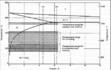
FIGURE 2-7 PORTION OF ALUMINUM-COPPER BINARY PHASE DIAGRAM. TEMPERATURE RANGES FOR ANNEALING, PRECIPITATION HEAT TREATING, AND SOLUTION HEAT TREATING ARE INDICATED.THE RANGE FOR SOLUTION TREATING IS BELOW THE EUTECTIC [18]. ... 17
FIGURE 2-8 EFFECT OF PHOSPHORUS REFINEMENT ON THE MICROSTRUCTURE OF AL-22SI-1NI-1CU ALLOY.(A)UNREFINED.(B)PHOSPHORUS-REFINED. (C) REFINED AND FLUXED.ALL 100X [6]. ... 18
FIGURE 2-9SCHEMATIC OF SOLUTIONIZING AND AGING PROCESS. ... 19
FIGURE 2-10TEM OBSERVATIONS OF THE EVOLUTION OF THE MICROSTRUCTURE DURING AGING: (A)GP ZONE; (B) Θ′′;(C) Θ′; (D) Θ [25]. ... 22
FIGURE 2-11THE EFFECT OF AGING TEMPERATURE ON THE SEQUENCE OF PRECIPITATE [24]. ... 22
FIGURE 2-12ALUMINUM–COPPER PHASE DIAGRAM ALONG WITH METASTABLE PHASE BOUNDARIES AT ALUMINUM END [24]. ... 22
FIGURE 2-13ILLUSTRATION OF THE MACHINING ENVIRONMENT. ... 24
FIGURE 2-14 THE GEOMETRY OF ORTHOGONAL CUTTING [58]. ... 27
IX FIGURE 2-16 BEHAVIOR OF CUTTING FORCES GENERATED BY DIFFERENT CUTTING TOOLS IN
TURNING OF ALUMINUM [17]. ... 29
FIGURE 2-17VISUALIZATION OF BASIC TERMS IN ORTHOGONAL CUTTING [57]. ... 30
FIGURE 2-18TEMPERATURE GRADIENT ACROSS TOOL AND WORKPIECE DURING MACHINING [27]. ... 32
FIGURE 2-19TYPES OF TOOL WEAR ACCORDING TO STANDARD ISO3685:1993[57]. ... 34
FIGURE 2-20 FLANK WEAR EVOLUTION WHEN DRILLING AL-SI ALLOYS AND MMC USING PCD TIPPED DRILLS [27]. ... 35
FIGURE 2-21EXAMPLES OF (A) SHOWS CONTINUOUS CHIP FORMATION. (B) SHOWS CONTINUOUS CHIP FORMATION WITH BUE, (C) SHOWS DISCONTINUOUS CHIP FORMATION [52]. ... 36
FIGURE 2-22 EFFECT OF FEED RATE ON THE MORPHOLOGY OF CONTINUOUS CHIPS DURING MACHINING OF UNSA97075-T6(AL-ZN) AND UNSA92024-T3(AL-CU) ALLOYS [61]. ... 37
FIGURE 2-23 (A)BUE DEVELOPED DURING DRY TURNING OF AA2024-T351 AT CUTTING SPEED 60 M/ MIN , FEED =0.1 MM AND RAKE ANGLE 0 DEGREES; (B) SURFACE FINISH WITHOUT BUE;(C) SURFACE FINISH WITH BUE ON THE TOOL EDGE [52]. ... 38
FIGURE 2-24 DISCONTINUOUS CHIPS OBTAINED FROM BRITTLE WORK MATERIAL, LOW CUTTING SPEEDS, LARGE FEED AND DEPTH OF CUT [52]. ... 39
FIGURE 3-1ELECTRIC RESISTANCE FURNACE.. ... 54
FIGURE 3-2BOOK MOLD AND CAST MACHINING BLOCK. ... 54
FIGURE 3-3BLUE M FORCED AIR HEAT TREATMENT FURNACES. ... 56
FIGURE 3-4T5,T6 AND T7 HEAT TREATMENT REGIMES. ... 56
FIGURE 3-5(A)MTSSERVOHYDRAULIC MECHANICAL TESTING MACHINE,(B) ATTACHABLE STRAIN GAUGE. ... 57
FIGURE 3-6CNCHURONKXFIVE 5-AXIS MACHINE. ... 59
FIGURE 3-7REMOVAL OF LAYERS FROM A CAST BLOCK (A) SCHEMATIC, AND (B) ACTUAL BLOCK. ... 59
FIGURE 3-8 (A)CONSTRUCTION OF A 3-COMPONENT DYNAMOMETER (FX ,FY &FZ), (B) SENSOR ARRANGEMENT OF THE TABLE DYNAMOMETER ... 62
FIGURE 3-9RAW DATA EXTRACTED FROM THE CUTTING FORCE MEASURING SYSTEM SHOWING FX, FY,FZ AND FR FOR ALLOY A. ... 64
FIGURE 3-10FREQUENCY DOMAIN BEFORE AND AFTER APPLYING DIGITAL FILTRATION. ... 65
FIGURE 3-11(A)DEFINING NUMBER OF CYCLES, (B) ILLUSTRATION OF CUTTING FORCES BEFORE AND AFTER CORRECTION. ... 67
X
FIGURE 3-13 MITUTOYO SJ-410 MEASURING INSTRUMENT. ... 69
FIGURE 3-14 MEASUREMENT OF RESIDUAL STRESSES IN THE BLOCK AT THE END OF THE MILLING PROCESS. ... 71
FIGURE 3-15LEICA DMLM OPTICAL MICROSCOPE. ... 73
FIGURE 3-16STRUERS TEGRAPOL-35GRINDER-POLISHER. ... 73
FIGURE 4-1 OPTICAL MICROSTRUCTURES OF ALLOYS IN THE AS-CAST CONDITION: (A) HT200 ALLOY,(B) 319 ALLOY,(C)356 ALLOY. ... 77
FIGURE 4-2BACKSCATTERED ELECTRON IMAGES OF:(A) ALLOY D; (B) ALLOY C IN T7 CONDITION, (C) ALLOY E IN T6 CONDITION.PFZ= PRECIPITATE FREE ZONES. ... 79
FIGURE 4-3 SCHEMATIC REPRESENTATION SHOWING THE INFLUENCE OF THE INCREASING AGING TEMPERATURE ON THE SIZE , DENSITY ,AND INTER-PARTICLE SPACING OF THE HARDENING PRECIPITATES : (A) AT A LOW AGING TEMPERATURE , AND (B) AT A HIGH AGING TEMPERATURE (L1 AND L2 INDICATE INTER-PARTICLE SPACING). ... 80
FIGURE 4-4RESULTANT CUTTING FORCES OBTAINED FOR (A) ALLOYS A,B AND C IN THE AS-CAST, T5 AND T7 HEAT-TREATED CONDITIONS, RESPECTIVELY; COMPARISON OF RESULTANT CUTTING FORCES (B) FOR COMMERCIAL ALLOYS E AND D, AND (C) FOR ALLOY C WITH ALLOY D. ... 83
FIGURE 4-5(A)CUTTING EDGE OF NEW INSERT,(B) CUTTING EDGE AFTER MACHINING 120 M,(C) FACE OF NEW INSERT, (D) FACE OF THE INSERT AFTER MACHINING 120 M IN ALLOY A. ... 84
FIGURE 4-6 (A)CUTTING EDGE OF NEW INSERT (B) CUTTING EDGE AFTER MACHINING 120 M (C) FACE OF NEW INSERT (D) FACE OF THE INSERT AFTER MACHINING 120 M - ALLOY C. ... 85
FIGURE 4-7 (A)CUTTING EDGE AFTER MACHINING 120 M OF ALLOY C,(B) CUTTING EDGE AFTER MACHINING 120 M OF ALLOY D,(C) FACE OF THE INSERT AFTER MACHINING 120 M OF ALLOY C, (D) FACE OF THE INSERT AFTER MACHINING 120 M OF ALLOY D. ... 88
FIGURE 4-8PORTABLE X-RAY MACHINE [13]. ... 89
FIGURE 4-9RESIDUAL STRESSES MEASURED BY X-RAY DIFFRACTION TECHNIQUE IN THE MILLING DIRECTION. ... 90
FIGURE 4-10CRITERIA FOR DEFINING THE SURFACE ROUGHNESS:(A) RA,(B)RZ,RT ACCORDING TO ISO 4287. ... 92
FIGURE 4-11MEASUREMENTS OF SURFACE ROUGHNESS FOR THE FIVE ALLOYS STUDIED. ... 93
FIGURE 4-12SURFACE ROUGHNESS AFTER MILLING FOR 120 M:(A) ALLOY A, (B) ALLOY C. ... 93
FIGURE 4-13SURFACE ROUGHNESS AFTER MILLING FOR 120 M:(A) ALLOY D, (B) ALLOY E. ... 93 FIGURE 4-14 BURRING FORMATION AFTER 120 M MILLING DISTANCE: (A) ALLOY C,(B) ALLOY E. 94
XI FIGURE 4-15 CHIP SHAPE AFTER 120 M MILLING DISTANCE OBTAINED FROM: (A) ALLOY C,(B)
ALLOY E. ... 95
FIGURE 4-16 SHAPE OF THE CUTTING INSERTS FOR DIFFERENT CONDITIONS: (A) FRESH TOOL, (B)
DULL TOOL- SIDE,(C) DULL TOOL- EDGE, AND (D) DULL TOOL AFTER MACHINING ALLOY E... 97 FIGURE 4-17 CUTTING FORCES FOR BOTH NEW AND DULL INSERTS (14 M OF MACHINING DISTANCE). ... 98 FIGURE 4-18 PROFILES OF THE MACHINING SURFACE OF ALLOY E: (A) FRESH INSERTS - 120 M MACHINING DISTANCE, AND (B) DULL INSERTS -14 M MACHINING DISTANCE. ... 100 FIGURE 4-19 COMPARISON OF ROUGHNESS PARAMETERS FOR THE FIVE ALLOYS USING NEW INSERTS (120 M MACHINING DISTANCE) AND DULL INSERTS (14 M MACHINING DISTANCE). . 101 FIGURE 4-20 COMPARISON OF SURFACE FINISH OF ALLOY C: (A) NEW INSERTS AND (B) DULL INSERTS. ... 102 FIGURE 4-21SURFACE FINISHING USING DULL INSERTS: (A) ALOY A,(B) ALLOY C,(C) ALLOY E.102 FIGURE 4-22RESIDUAL STRESSES MEASURED IN THE TRANSVERSE DIRECTION FOR ALLOY C. .... 103 FIGURE 4-23SHAPE OF THE CHIPS OBTAINED USING DULL INSERTS:(A) ALLOY A, (B) ALLOY C AND
(C) ALLOY E. ... 104 FIGURE 4-24 EXAMPLES OF BURR FORMS DURING MILLING OPERATION [31]... 105
XII
LIST OF TABLES
TABLE 2-1CLASSIFICATION OF CAST ALUMINUM ALLOYS ... 8
TABLE 2-2FACTORS INFLUENCING MACHINING OPERATION ... 26
TABLE 3-1CHEMICAL ANALYSIS OF THE ALLOYS. ... 53
TABLE 3-2ROUGHNESS EVALUATION PARAMETERS. ... 70
TABLE 3-3MEASUREMENT CONDITIONS FOR DETERMINATION OF RESIDUAL STRESSES USING X-RAY TECHNIQUE ... 72
TABLE 4-1TENSILE PROPERTIES OF THE STUDIED ALLOYS. ... 77
TABLE 4-2 EVALUATION OF THE MAX HARDNESS VALUES HV AT 10µM BELOW THE MACHINED SURFACE ... 91
LIST OF EQUATIONS
EQUATION 1CUTTING FORCE IN X DIRECTION. ... 62EQUATION 2CUTTING FORCE IN Y DIRECTION. ... 62
EQUATION 3CUTTING FORCE IN Z DIRECTION. ... 62
1
CHAPTER 1
2
CHAPTER 1
1 INTRODUCTION
1.1 INTRODUCTION
From the early 1900s, aluminum and its alloys have gained increasing attention. Aluminum is a promising material, due to its exceptional mechanical and physical properties. These properties comprise its light weight due to its low density, good formability, high corrosion resistance, high electrical and thermal conductivity, high stiffness and better high temperature strength. Aluminum alloys are versatile materials that find application in several industries. Figure 1-1 shows the main consumer segments being transportation, construction and packaging. [1]The economic output of the aluminum industry is $174 billion [2]. The economic impact of the industry finds its basis in job creation and recycling of aluminum. Some 692,000 U.S. jobs were created related to the production, processing and use of aluminum in diverse applications [2]. Aluminum is 100 percent recyclable, making the metal one of the most recyclable of all materials. According to the Aluminum Association, recycling of aluminum has a positive environmental impact in reducing the cost of the energy consumption by 90% compared to that required for primary production of aluminum. [1]
3 According to the 2018 annual report of Norsk Hydro, the highest usage of aluminum is in the transportation sector, 27 percent [2]. The main objective in the automotive industry is to increase fuel economy and reduce air pollution. Aluminum alloys can achieve these targets due to their light weight compared to steel and cast iron, materials previously used in automotive vehicles. Each pound of aluminum replaces nearly two pounds of steel. Aluminum also has a higher energy absorption capacity in relation to crash testing. The specific energy absorption of aluminum was found to be twice that of steel during an experimental study preformed on structural steel (DP600) and structural aluminum (AA5754) U-beams in high speed crash testing. [3]. With these advantages, the use of aluminum alloys in the automotive industry has developed rapidly within the last decades. Parts such as radiators, wheels, cylinder heads, engine blocks, hoods, doors and car body are now made of aluminum. The reduction in the vehicle’s overall weight results in reduction in fuel consumption and air pollution. Passenger vehicles with aluminum intensive design (AIV) have been reported to show a 17 percent reduction in CO2 emissions [4].
Automotive castings producers specializing in the production of complex aluminum structural components play an important role in vehicle manufacturing. With a view to improving the quality of these components, the development of new alloys is continuously being investigated to meet with the increasing demands of new designs that operate at higher service temperatures which require alloys which can maintain their strength at these high temperatures. Increasing the alloy strength is often at the expense of machinability and may affect manufacturing costs. The integration of a new alloy requires carrying out several
4 machining tests, in order to understand the behavior of the alloy from the point of view of the quality of the machined parts and wear of the cutting tools.
As Figure 1-2 indicates, the consumption of aluminum in light vehicles has exhibited an increasing trend since 1975, and is expected to increase to 565 pounds per vehicle by 2028 in North America [5].As a result of this incresing demand, industrialists, specifically automakers, are willing to invest money in order to improve existing commercial alloys as well as creating new alloys. The improvement regarding existing alloys is achieved by either enhancing their mechanical properties such as hardness, tensile strength and impact toughness, or by optimizing manufacturing techniques which is achieved by understanding the machinability characteristics of the alloy in question.
Machining is an important and essential part of the manufacturing process. With the progress in technology development over the last decades, it is easy nowadays to attain a final product with precise dimensions as well as an impressive surface quality. The three main machining processes are milling, turning and drilling. These operations should be
Figure 1-2 Aluminum consumption in light vehicles in North America from 1975 to 2028. [5]
5 controlled, monitored and optimized to achieve cost effective and sustainable products. This may be achieved by understanding the cutting process and the factors affecting it such as cutting parameters, cutting tool selection, lubrication, etc.The cutting process is suitable for machining almost all materials (ferrous and non-ferrous, soft and hard, ductile and brittle, etc.) [6,7].
With regard to the machinability of aluminum alloys, it is also important to take into consideration the condition of the workpiece (casting) which is controlled by factors such as the alloy composition, microstructure, porosity, heat treatment and properties. According to Elgallad et al. [8] and Tash [9], the machinability of conventionally cast Al-Cu alloys depends primarily on the shape, size and distribution of the eutectic and Al2Cu precipitation present in the microstructure. The present research study was carried out to investigate the effect of heat treatment conditions on the mechanical properties and the machinability behavior, in particular the milling characteristics, of a recently developed Al-Cu cast alloy, in order to compare its performance with those of well-defined Al-Si based reference alloys, namely 356-T6 and 319-T7 alloys used in automotive components. The machinability characteristics were investigated using a cutting tool with sharp cutting inserts, and compared with those obtained with dull cutting inserts. The results obtained using dull inserts is a supportive evidence for the importance of avoiding the use of the dull inserts while preforming machining operations.
6
1.2 REFRENCES
[1] "Hydro Annual report 2018," Norsk Hydro ASA, Oslo Norway, 2019.
[2] "The Aluminum Association," 2019. [Online]. Available:
https://www.aluminum.org/aluminum-advantage/economic-impact-aluminum.
[3] Clark, G & Almond, D & Reynolds, Neil & Hughes, Darren & Pharaoh, M & Williams, "Comparative energy absorption of U-beams in high-speed crush testing: Thermoplastic composite, steel & aluminum," in International SAMPE Technical Conference., 2013.
[4] S. Das, "Life Cycle Energy and Environmental Assessment of Aluminum-Intensive Vehicle Design," SAE International Journal of Materials and Manufacturing, vol. 123, no. 5, 2014.
[5] "Statista," Ducker, 2018. [Online]. Available:
https://www.statista.com/statistics/496185/pounds-of-aluminum-per-car-in-north-america/.. [Accessed 15 April 2019].
[6] E.M. Trent, Metal Cutting, Butherworth-Heinemann, Oxford, UK, 3rd edition, 1991, 188-241. [7] P. Kovac, L. Sidjanin, Tribology in Industry, XVII (1995) 1, 12-16.
[8] E.M. Elgallad, F.H. Samuel, A.M. Samuel, H.W. Doty, Journal of Materials Processing Technology, 210 (2010) 13, 1754-1766.
[9] M. Tash, F.H. Samuel, F. Mucciardi, H.W. Doty, S. Valtierra, Materials Science and Engineering A, 434 (2006) 207– 217.
7
Chapter 2
8
Chapter 2
2 SURVEY OF THE LITERATURE AND OBJECTIVES
2.1 Al-Cu AND Al-Si-Cu/Mg ALLOYS
Aluminum and its alloys have been widely used in many high technology industries such as automotive, marine and aerospace, due to their exceptional mechanical and physical properties. These properties comprise lightweight based on the low density of aluminum, good formability, high corrosion resistance, high electrical and thermal conductivity, high stiffness and improved high temperature strength. Aluminum cast alloys are designated by a three-digit system followed by a decimal place. This classification is based on major alloying element(s). The classification system proposed by the Aluminum Association is commonly recognized worldwide. The alloys are also classified according to the percentage of alloying elements present: (i) major alloying elements including silicon, copper and magnesium; (ii) minor alloying elements such as nickel and tin; (iii) microstructure-modifying additives, like strontium, boron, sodium, phosphorus, chromium, etc. and (iv) impurity elements, such as iron, for example [1].Table 2-1 below lists the different family of aluminum alloys corresponding to the major alloying element(s)
9 The overall physical properties of an alloy depend on the properties of the major alloying elements. The weight or volume fraction and the morphology of major phases present has a significant effect on the properties of the alloy. [2]
2.2 Al-Si ALLOYS
The aluminum silicon alloys (Al-Si) are the largest group of cast alloys due to their properties such as, elevated wear resistance, low thermal expansion, high thermal and electrical conductivity, and high strength-to-weight ratio, and high hardness. These properties make them very suitable for use in the production of several automotive parts such as radiators, wheels, cylinder heads, engine blocks, hoods, doors and car body applications. [3] According to the Aluminum Association, classification the aluminum silicon cast alloys belong to 3XX.X and 4XX.X series. The former are Al-Si alloys containing Cu and/orMg, while the 4XX.X series are Al-Si alloys.
Figure 2-1 Aluminum rich portion of the Al-Si phase diagram [21].
10 The phase diagram of Al-Si alloy is a simple binary diagram, the maximum solid solubility of silicon in aluminum is 1.65% [4]. The Al-Si eutectic occurs at 12.2% Si, at a temperature of 577 °C. The range of silicon content in Al-Si commercial alloys varies from 5 up to 23 wt% as illustrated in Figure 2-1 [5]. The Si concentration of alloys used in the automotive industry often ranges between 5 and 10 wt.%. Its presence enhances the fluidity and improves feeding which reduces shrinkage porosity, thus parts having complex designs with varying thickness can be achieved. Silicon also increases the alloy strength as well as stiffness, but reduces the ductility [6]. Al-Si alloys are classified according to their Si content: hypoeutectic alloys contain 5 to 10% silicon; in eutectic alloys the Si content ranges from 11 to 14%; while hypereutectic alloys contain 14 up to 25 wt% Si. The corresponding microstructures that form are shown in Figure 2-2 [7].
Figure 2-2(a) Microstructure of hypoeutectic alloy (1.6-12.6% Si) 150X. (b)Microstructure of eutectic alloy (12.6% Si). 400 X. (c) Microstructure of hypereutectic alloy (>12.6% Si). 150X [7].
11 The main phases present in Al-Si alloys are the primary α-Al phase and silicon. The hypoeutectic alloys are characterized by having alpha-aluminum that solidifies first in dendritic morphology (tree-like structure) surrounded by eutectic Al-Si, while in hypereutectic alloys, the primary silicon solidifies first and surrounded by eutectic Al-Si [8]. The dendritic structure of the alpha aluminum crystals is defined by two terms, primary dendrite arm spacing (PDAS) and secondary dendrite arm spacing (SDAS). The cooling rate during solidification is the key factor that controls the values for PDAS and SDAS [5] [9]. The eutectic Al-Si structure as well as pure silicon particles are formed in the liquid surrounding the dendrite structure. Figure 2-3 shows nucleation of the α-Al dendrites in an Al-Mg alloy [63].
Figure 2-3 Nucleation of the dendritic structure of alpha Aluminum in an Al-Mg alloy (after Lix et al. [63]).
12
2.2.1 EFFECT OF ALLOYING ELEMENTS ADDITIONS TO Al-Si ALLOYS
The characteristics of Al-Si alloys are enhanced by the addition of certain alloying elements. Properties such as hardness and tensile strength may be greatly improved by the addition of alloying elements such as Cu and Mg in minor quantities, through the formation of the strengthening precipitates CuAl2 and Mg2Si within the microstructure after heat treatment.
2.2.1.1 EFFECT OF COPPER ADDITION TO AL-Si BASED ALLOYS
Addition of copper to Al-Si alloys has a positive impact on the mechanical properties. Tensile strength and hardness of the alloy are enhanced at both elevated and room temperature [10]. The increased matrix hardness has an impact on improving the machinability of the alloy. The enhancement in the properties of the alloys is optimized by a selective heat treatment procedure. The heat treatment process will result in fine spheroidal copper precipitates that are homogenously dispersed in the aluminum matrix. Addition of copper will result in reduction of both ductility and resistance to corrosion of the alloy. Sigworth [11] concluded that addition of copper up to 1.8% has a significant effect on enhancing Al-9%Si-0.5%Mg cast alloy, accompanied by a slight reduction in the ductility. Copper phases are precipitated during solidification mainly in three different forms (i) fine eutectic Al-Al2Cu, (ii) block-like Al2Cu, and (iii) Q-Al5Mg8Cu2Si6.
Figure 2-4 Block like Al2Cu phase and the Blocky form of Q-phase (after E. Samuel et al. [64] ).
13
2.2.1.2 EFFECT OF MAGNESIUM ADDITION TO Al-SI ALLOYS
Addition of Mg has the same strengthening effect as Cu but with increased reduction in the ductility. Mechanical properties such as tensile strength, yield strength as well as hardness are enhanced but the presence of Mg in Al-Si alloys has a great effect on reducing their ductility [12]. According to Dunn and Dickert [13], the addition of 0.55% Mg to the A380 and 383 cast alloys enhanced the mechanical properties, however it was clear that the Mg caused a reduction in the ductility of the alloy. Samuel et al. [68] studied the effect of Mg addition to 319 alloys containing iron. The authors reported that a large portion of the β-Al5FeSi iron intermetallic phase is transformed to the π- Al8Mg3FeSi6 Chinese script phase, as shown in Figure 2-5.
Figure 2-5 Thick arrow points to the B-Al5FeSi phase transformingtoπ- AL8Mg3FeSi6 phase, thin arrow represents the Mg2Si phase (after E. Samuel et al. [64] ).
14
2.2.1.3 EFEECT OF IRON ADDITION TO AL-SI ALLOYS
Iron (Fe) is an impurity element that is present in aluminum from the extraction process. The solid solubility of Fe in aluminum is low (0.05%), so that any amount in excess tends to form different intermetallic compounds. These Fe-intermetallics provide an increase in the yield strength (~7 MPa/vol%). However, their effect on strength depends on their size, chemistry, as well as their distribution. Iron constituents can also cause cracking and notches, which will result in a negative impact on fatigue resistance [15]. The remaining undissolved iron has high potential to combine with other alloying elements to form different types of intermetallic phases. Some of the more commonly observed phases are displayed in the optical microstructures of Al-5Si-1Cu-0.5Mg-Fe alloy shown in Figure 2-6, revealing the morphologies of these Fe-containing intermetallics.
Figure 2-6 :(a)β-Al5FeSi platelets; (b) script-likeα-Al8Fe2Si;(c)π-Al8FeMg3Si6 phase growing fromβ;(d)script-likeπ-phase (after J. A. Taylor [65] ).
15 The iron intermetallic constituents formed depend on the chemical composition of the alloy as follows:
(i) In the absence of Si in the alloy as a dominant alloying element, Fe tends to combine with Al forming Al3Fe and Al6Fe;
(ii) In the presence of Si in the alloy, the orthorhombic Chinese script like α-Al8Fe2Si and the monoclinic platelet-like β-Al5FeSi appearing as needles in a two-dimensional micrograph - are formed;
(iii) In the presence of Si and Mg in the alloy, an alternate phase, π-Al8FeMg3Si6 can form. Another phase that forms when Mn is also present with Si is the cubic Al15(Fe,Mn)3Si2, also called the α-Fe phase.
16
2.3 ALUMINUM COPPER ALLOYS
Aluminum-copper (Al-Cu) alloys are widely used in both wrought and cast form. The Al-Cu cast alloys belong to the 2XX.X series. Alloys such as 201, 203, 206 have a Cu content of 4-5 wt%, while alloys such as 240 and 222 contain 8 wt% Cu and 10 wt% Cu, respectively [16]. The Al-Cu binary alloy system has maximum solubility of 5.7 wt% Cu at the eutectic temperature of 548°C, as shown in the phase diagram. The chemical composition of the Al-Cu alloy gives it the privilege to record the highest strength of all Al cast alloys. The eutectic is formed at 33.2% Cu at temperature of 548 °C. Alloys containing a copper content below 33.2 wt% are termed hypoeutectic alloys, where the primary α-Al dendritic phase solidifies first, followed by solidification of the remaining liquid in the interdendritic regions to form the eutectic Al + CuAl2 eutectic. The copper content in the CuAl2 or θ phase lies between 52.5 and 54.1% [17].
These alloys are suited for applications where high strength and hardness are required at both room and elevated temperature. Al-Cu alloys exhibit excellent strength, thus making them suitable for automotive, marine, and aerospace applications. Because of the elevated density of Cu, 8.92 g/cm3, however, the high Cu content of Al-Cu alloys increases the weight of the cast parts manufactured from these alloys. The Al-Cu alloys generally have lower resistance to corrosion compared to other Al alloys, as well as poor resistance to hot cracking.
17 The marginal presence of silicon - less than 0.1 wt% - in some Al-Cu alloys may be considered as an impurity. Such a low Si level has a detrimental effect on the alloy castability and fluidity. Thus, producing castings with complex designs incorporating thin sections and pressure-tight parts is barely achievable. As a result, an appropriate gating and feeding system design is necessary. A combination of tensile properties and ductility can be attained with controlled additions of impurities (Si and Fe). Grain refining elements are usually added in the melt treatment stage to improve properties of the cast alloy. Alloys containing 4-5.5%Cu exhibit a significant improvement in strength following heat treatment [18]. Silver accelerates the aging response and reduces the risk of stress corrosion.
Also, copper has a significant impact on the strength and hardness of aluminum castings at both ambient and elevated service temperatures (up to 300 ℃) [19] So, the mechanical properties of these alloys may be improved via solution heat treatment and age hardening through the formation of CuAl2 precipitates. The morphology of these precipitates changes according to the heat treatment process applied [18].
Figure 2-7 Portion of aluminum-copper binary phase diagram. Temperature ranges for annealing, precipitation heat treating, and solution heat treating are indicated. The
18
2.4 MELT TREATMENT
Mechanical properties can be further enhanced during the melt treatment process, where morphologies and distribution of phases present, as well as the grain size can have a significant effect on the properties. Minor alloying elements, known as microstructure modifiers, are often added to the melt. Elements such as strontium (Sr) and sodium (Na) modify the needle-like morphology of the eutectic silicon in Al-Si alloys to a fine fibrous form, while the effect of phosphorus addition to hypereutectic Al-Si alloys refines the coarse structure of primary silicon crystals, by reducing their size by a factor of 10. The unrefined structure of the silicon crystals has a harmful effect on tool life when machining is carried out. Phosphorus is added to the molten metal in the form of phosphorus-containing compounds or metallic forms such as phosphorus pentachloride and phosphor-copper, respectively. Inert gas fluxing is applied to activate aluminum phosphide nuclei [6].
Figure 2-8 Effect of phosphorus refinement on the microstructure of Al-22Si-1Ni-1Cu alloy. (a) Unrefined. (b) Phosphorus-refined. (c) Refined and fluxed. All 100x [6].
19
2.5 HEAT TREATMENT
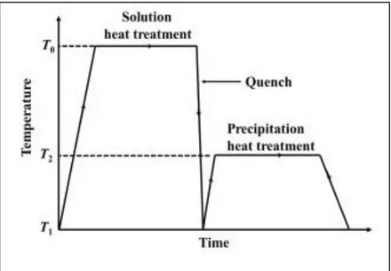
Thermal treatment is technique used to enhance the mechanical properties of heat-treatable alloys. The enhancement is achieved through modifications to the microstructure of an alloy brought about by the heat treatment steps. These comprise a controlled sequence of heating and cooling processes where time and temperature are the main parameters. The T6 and T7 tempers are the common heat treatment processes that are applied to Al alloys to enhance their properties. The strengthening effect is gained from the precipitation of secondary hard phases embedded within the soft aluminum matrix [18]. The T6 and T7 treatments are expressed in Figure 2-9 , showing three stages: (i) solution heat treatment, followed by (ii) quenching, and then (iii) age hardening or precipitation heat treatment.
20
2.5.1 SOLUTION HEAT TREATMENT
The alloy is heated and held to a temperature close to the eutectic temperature, where alloying elements such as Cu and Mg are dissolved into solid solution. The amount of the solutes present usually exceeds their solid solubility limit. The main target of the solution heat treatment stage is to obtain a homogeneous suppersaturated solid solution (SSSS) where most of the hard phases such as CuAl2 and Mg2Si are dissolved. The solution treatment temperature depends on the alloy composition and solid solubility limits. The chemical composition of an alloy will control the different phases formed during solidification. Phases containing iron such as π-Al8FeMg3Si6 and α-Al8Fe2Si are harder to dissolve due to the limited solubility of iron in aluminum (0.05%). Furthermore, the solution treatment temperature must be lower than the melting points of the phases present to avoid incipient melting, which would lead to porosity formation and a reduction in the mechanical properties.
The solution treatment temperature ranges between 510 ℃ and 550 ℃ for an Al-4.5 wt% Cu alloy, for the Cu to be completely dissolved in solid solution [16]. Wang et al. [20] recorded an improvement in the mechanical properties of an Al-Si-Cu-Mg cast alloy when solution heat treatment was carried out at 520 ℃ without the occurrence of incipient melting of the phases present. However, as a precaution, Abdelaziz [21] used a temperature of 495 ℃ for Al-Si-Cu-Mg alloys to avoid any possibility of incipient melting [22].
21
2.5.2 QUENCHING
The supersaturated solid solution (SSSS) obtained with solution heat treatment is then subjected to a rapid cooling process termed quenching. During quenching, the SSSS structure is preserved at ambient temperature with many vacancies in its lattice structure. These vacancies are active nucleation sites for precipitates to form. Selection of quenching rate is based on the quenching sensitivity of the alloy. A high quenching rate is desirable to avoid precipitation of the hardening solutes (CuAl2 and Mg2Si) to maintain them in solid solution form within the SSSS microstructure. The rate of quenching has an impact on residual stresses, intergranular corrosion resistivity and strength of the material [23].
2.5.3 AGE HARDENING
The main target of the aging stage is to maximize the formation of fine homogenously dispersed hardening precipitates characterized by high matrix coherency and tight spacing between adjacent precipitates. Solute atoms form clusters due to the supersaturation of vacancies in the SSSS, which allows diffusion. Clusters fit coherently in the structure of the aluminum lattice. These clusters of solute atoms are called GP zones. These are metastable regions where enough energy is present to enable precipitates to form. Clusters of solute atoms are formed and precipitation occurs due to rejection of solute atoms from the super-saturated solid solution. The formed precipitates are transitional metastable phases. The morphology of the phase is affected by the aging temperature and aging time. The sequence of formation of CuAl2 precipitates is as follows:
22 As aging time proceeds the GP zones are dissolved and the θ’’ phase starts to form, leading to increase in hardness and strength. With further increase in aging time, the strength
and hardness start to deteriorate due to dissolution of θ’’ which is transformed to θ’, when the alloy is said to be overaged. Finally, the stable form of θ precipitates is observed. Clusters have a disk-like morphology, they grow in diameter and thickness as the precipitation sequence is followed, as illustrated in Figure 2-10 [24].
Figure 2-12 illustrates the effect of aging temperature on the sequence of precipitates. The temperature of the precipitates formed depends on the Cu concentration (wt%) in the matrix phase. As Figure 2-11 illustrates, the precipitation temperatures increase as the Cu content in the matrix increases.
Figure 2-10 TEM observations of the evolution of the microstructure during aging: (a) GPzone;(b)θ′′;(c) θ′;(d)θ[25].
Figure 2-11 The effect of aging temperature on the sequence of precipitate [24]. Figure 2-12 Aluminum–copper phase
diagram along with metastable phase boundaries at aluminum end [24].
23
i. T1<T<T0 the only precipitate that is possible is the stable non-coherent phase of θ.
ii. When T2<T<T1 both GP zones and θ′′ vanish; as the aging process proceeds, the
outcome of precipitates is θ′→θ.
iii. When T3<T<T2 GP zones completely disappear with progress of the aging
process, the outcome of precipitates is θ′′→θ′→θ.
iv. When T<T3 the main precipitates present are the GP zones; with the progress of
aging process, the outcome of precipitates is GP zones →θ′′→θ′→θ.
The fine precipitates fill the defective zones at grain boundaries, point dislocations and fill most of the imperfections within the lattice structure. The precipitates cause local distortion and strain fields that hinder dislocation movement, resulting in an enhancement of the mechanical properties.
24
2.6 MACHINABILITY
Machinability of a material can be expressed in many terms. It is the study of the interactions between tool, considering its material and design, and the workpiece considering its material composition and heat treatments applied. These interactions are tested through a selected machining operation such as milling, turning or drilling, etc. The machining operation is controlled by a set of cutting parameters like cutting speed, feed rate depth of cut for a specific machining environment as shown in Figure 2-13.
Machinability is also defined as the material response to machining. According to the American Iron and Steel Institute (AISI), machinability can also be expressed in terms of how easy or difficult a material can be to machine compared to a 160 Brinell hardness B1112 cold drawn steel, machined at 180 surface feet per minute. Machinability of a certain material is evaluated based on one or more of the following factors: (a) tool life, (b) cutting forces, (c) chip formation, and (d) quality of the machined surface. In the following sections, machinability of aluminum alloys is explained referring to the above-mentioned machinability criteria.
25 Machining is the leading type of forming process; however, due to technology developments, this type of production has changed over the last decades. Nowadays it is easy to attain a final product with precise dimensions as well as impressive surface quality. Machining operations should be controlled, monitored and optimized to achieve cost effective and sustainable products. The machining process is monitored and optimized by a clear understanding of the cutting process and the factors affecting it such as cutting parameters, cutting tool selection, lubrication, etc. Machinability of an alloy is assessed based on the following:
i. Cutting forces generated
The cutting forces usually express the overall power consumption; the greater the cutting force the higher the power consumption of the machine.
ii. Tool life and tool wear
Tool life can be expressed as the duration where the cutting edge is applicable to produce products prior to tool failure, while tool wear may be expressed as an inevitable gradual failure of the tool. The tool condition directly impacts the material removal rate (MMR) which is the volume of material removed per unit time.
iii. Product quality
The quality of the product includes the surface roughness and dimensional tolerance. The roughness of the machined surface has a great impact in mechanical meshing between parts and is thus critical.
26
iv. Chip formation
Chips are formed as three different types (i) continuous chips, (ii) discontinuous chips, and (iii) continuous chips with built up edges (BUE). The formed chips have a major role in cutting heat dissipation from the workpiece.
Table 2-2 Factors influencing machining operations.
To be able to evaluate the machinability of an alloy, it is necessary to have a clear understanding of the factors and parameters that influence the machining operation as a whole. These factors, summarized in the Table 2.2 below, will be discussed in the following sections.
Factors Influence on the machining operation
Cutting parameters: cutting
speed, feed rate, depth of cut Cutting forces, tool life, heat generation, surface finish. Tool design: tool angles rake,
relief and clearance angle Influence chip flow direction, reduction in tool wear.
Tool wear Dimensional accuracy, surface quality, cutting forces, heat generation.
Continuous chips Good surface finish, stabilized cutting forces, undesirable results in increase in the down time in automated machining due to clogging. Discontinuous chips Desirable due to ease of chip disposal, may affect the surface quality,
fluctuation of the cutting forces resulting in vibration and tool chatter. Built up edge chips Affect tool geometry resulting in poor surface finish, desirable only
when thin as it may protect the cutting tool edge.
Temperature rise Influence tool life by enhancing crater wear, may cause thermal damage to the workpiece.
27
2.6.1 CUTTING FORCES GENERATED AND FACTORS AFFECTING THEM
Machining of aluminum alloys generates cutting forces usually lower than that of steel by 70 %, this is due to the lower mechanical properties of aluminum alloys compared to those of ferrous alloys [19]. Aluminum has a low density compared to steel, which reduces the inertia force that prohibits high speed machining, resulting in overall reduction of the specific cutting forces. The variation of the cutting forces among aluminum alloys depends on the chemical composition, and hence the physical properties [25] [26]. Heat treatments and/or the addition of alloying elements that affect the mechanical properties (hardness or strength) of the alloy positively may reduce the machining forces as the chip-tool contact area is reduced [27] [28] [29].
By increasing machining cutting speed, the machining forces are reduced since the increase in the cutting force will increase cutting temperature, leading to a reduction in the shear stress in the primary shear zone as well as the secondary shear zone(Figure 2-14). The stress at the secondary shear plane are usually 30% less than those of the primary shear [30] [31]. Overall increase in the cutting speed will reduce cutting forces but in some cases high speed cutting causes excessive increase in the deformation rates that may result in increased machining forces [32] [33].
28 High speed machining of alloys containing hard particles will result in elevated cutting forces due to excessive flank wear occurring to the cutting tool [34]. Figure 2-15 shows the effect of cutting speed on the generated cutting forces. Hard particles act as abrasive material on the cutting tool. Lahres et al. [35] found that, during high speed dry milling of AlSiMg cast alloy, material from the work pieces sticking on the cutting edges of the tool lead to flank wear; however, this problem can be reduced by the application of minimum quantity lubrication (MQL). Any increase in the depth of cut and/or feed rate will increase the area of the primary as well as the secondary shear planes - increase chip tool contact area- which in its turn will deteriorate the shearing process of the material and will result in increasing the cutting forces [36].
Tool design and tool geometry, such as rake angle and nose radius, have a great impact on the cutting forces. Any geometrical changes that occur in the tool geometry due to wear or built-up-edge (BUE) will strongly affect the machining cutting forces. Tools with increased rake angle reduce chip-tool contact area, therefore they will result in reducing the machining forces [37] [38]. Shankar et al. [39] reported that machining 6061-T6 aluminum alloy with a tool that has a reduction in the rake angle, results in increasing
29 the cutting force [39]. Also, tools with a large nose radius usually generate small rake angles that may increase the cutting forces [40].
Tang et al [39] concluded that flank wear generates high machining forces; this conclusion is based on the milling of aluminum alloy 7050-T7451. Flank wear increases contact area between tool and workpiece. According to ISO 513, the letter N is used as the standard designation for cemented carbide tools that are employed for machining aluminum alloys. Coated or diamond cutting tools do not react chemically with aluminum alloys, therefore such types of tools are less adhesive which will result in reduced cutting forces as reported by Roy et al. [40] during machining of pure aluminum by various types of tools, namely (1) uncoated silicon carbide, (2)TiC (titanium carbide)—CVD, (3)-TiN—CVD, (4)Al2O3 (aluminum oxide)—CVD, (5)-AlON (aluminum oxynitride), (6) TiB2 (titanium diboride)—PVD, and (7) diamond—HFCVD (hot filament chemical vapor deposition) as shown in Figure 2-16.
Figure 2-16 Behavior of cutting forces generated by different cutting tools in turning of aluminum [17].
30
2.6.2 TOOL LIFE AND TOOL WEAR
Various tool materials with different tool geometry can be used for machining aluminum alloys, such as high-speed steel (HSS), cemented carbides, and diamond-based tools. The proper selection of a tool is a must prior to the start of the selected machining operations. Moreover, the selection of tool material mainly depends on the chemical composition of the alloys and the presence of hard material embedded within the alloy matrix. HSS tools are satisfactory for machining all aluminum alloys expect Al-Si alloys, because these alloys are abrasive and should be machined with silicon carbide tools or diamond based tools due to their low chemical affinity for aluminum, which would enhance the surface finish of the workpiece [19]. Figure 2-17 illustrates the basic terms used for a cutting process.
Machining with cutting speeds within the range of 600 to 800 m/min and a carbide tool with rake angle ranging from 6 to 20 degrees is suitable for the turning of aluminum alloys that are free of hard particles. Toropov et al. [41] used N10 grade tools with different rake angles of −5°, 0°, 5°, 10°, and 20° and a cutting speed of 800 m/min during turning of Al6061-T6. The authors aimed at studying the effect of rake angle on burr height, and concluded that tools with rake angles of 10°, and 20° produce smaller burr height than those of −5°, 0° and 5°rake angles.
31 It is recommended for aluminum alloys containing about 12-16 vol% of hard particles of either Si or SiC to be machined with tools having rake angles of 0° to 7° and cutting speeds of 20 to 450 m/min regardless the type of tool material [27][25]. Ciftci et al. [42] performed turning tests on Al-2014 alloy matrix composites containing 8 and 16 vol% SiC using K10 (N10) inserts (5° rake angle) and cutting speeds ranging from 20 to 80 m/min.. A turning test was performed by Manna and Bhattacharayya [43] on Al/SiC (12 wt% Si and 15 vol% SiC) at a cutting speed of 235m/min using uncoated tungsten carbide K10 (now designated N10) with a rake angle of 5°.
For drilling operations of aluminum alloys it is recommended to use helical drills with helix angles of about 40° to 48° and point angles of 118° to 140°. Tools with deep flow grooves will facilitate chip flow and prevent the material from sticking on the drill’s rake face [19] [44] [45].
Diamond based tools are very efficient for machining high strength aluminum alloys at cutting speeds above 700m/min [27] [41], whereas polycrystalline diamond (PCD) tools are more suitable for machining alloys containing 10 to 20 vol% of ceramic particles or Si contents varying from 12 to 21 wt% because they are resistant to the thermally activated wear mechanisms [46]. The hardness of PCD tools is four times greater than silicon or ceramic particles. PCD tools have higher thermal conductivity compared to cemented carbides; therefore, less generation of cutting temperature is attained [47].
Diamond coated tools have been proved to improve the machinability of aluminum alloys due to their magnificent properties, high hardness at high temperatures, low friction coefficient, low adhesiveness, high thermal conductivity, and chemical stability. Diamond
32
coated tools reduce BUE, abrasive wear as well as cutting forces; they also produce a good surface finished product.
Tool wear is a non-desirable change that alters the tool geometry from its original shape. The geometrical changes resulting from wear affect the performance of the tool. Tool wear has a great impact on the machining process as well as on the quality of the work piece being machined. The cutting force increases in machining operations due to gradual wear of the tool, as a result of the friction and relative movement of the tool and workpiece. Tool wear can be of different types such as (i) abrasive wear, (ii) adhesive wear,(iii) wear due to oxidation, (iv) tool wear as a result of diffusion and chemical decomposition, and (v) tool wear due to cyclic loading fatigue. The low melting point of aluminum leads to unelevated machining temperatures thus, thermally activated wear mechanisms such as oxidation, diffusion, fatigue and chemical decomposition do not usually occur. Figure 2-18 illustrates the temperature gradient during the interaction between tool and workpiece in orthogonal cutting.
Figure 2-18 Temperature gradient across tool and workpiece during machining [27].
33 Abrasive and adhesive tool wear are the most common mechanisms that occur while machining aluminum alloys. As the tool cuts through the workpiece, the soft material of the workpiece slides over the cutting edge of the tool. If the material of the workpiece contains small hard particles, the contact of these hard particles against the cutting edges of the tool may cause the machining temperature to increase, which lowers the resistance of the cutting tool thus adhesive and abrasive wear are accelerated. During machining process friction, temperature and pressure are usually generated. Parts of the soft material of the work piece tend to adhere to the hard material of the tool, and form what is called a built up edge (BUE).
Abrasive and adhesive wear usually occur when machining an alloy containing hard particles such as silicon carbide (SiC). Normally the percentage of these hard SiC particles of in the workpiece lies in the range of 10 to 20% of the alloy volume. The hardness of the SiC particles is higher than that of the cemented carbide tool material; therefore this causes the machinability of the aluminum alloys to decrease [38].
34 Figure 2-19 shows the common types of tool wear which include flank wear, crater wear, plastic deformation, nose wear, thermal cracking, mechanical fatigue cracking, chipping, fracture and BUE. Flank wear, carter wear and nose wear are the common ones that usually occur when machining aluminum alloys.
35 Flank wear occurs on the flank side of the tool due to abrasive wear of the cutting edge against the machined surface of the workpiece. Flank wear is non-uniform along the cutting tool edges, rate of flank wear increases with the size and volume percentage of hard precipitates in the matrix of the alloy [48]. Therefore, the less the dispersion of hard particles of Al2O3p and SiCp in the case of Al metal matrix composites (MMCs), the less
the flank wear. Crater wear occurs on the rake surface of the tool, due to friction between
the rake face and chips flowing across it, resulting in scars on the rake face. Coelho et al. [26] investigated the during drilling of hypoeutectic Al-Si alloy, hypereutectic Al-Si alloy and AA261-15vol% SiCp MMC; these materials contain hard particles of Si or SiCp. As Figure 2-20 shows, a progressive flank wear was noted when the test was carried out using PCD tools [49].
Tool wear will cause deformation in tool geometry that will mainly reduce the sharpness of the primary and secondary cutting edges, which will have consequences on the cutting forces and the product quality, as the latter is associated with the surface quality of the product and its dimensional tolerance.
Figure 2-20 Flank wear evolution when drilling Al-Si alloys and MMC using PCD tipped drills [27].
36
2.6.3 CHIP FORMATION
The process of chip formation is a critical issue in any machining process. The form of the chips greatly affects the machining operation as they have a great impact not only on tool life, but also on the integrity of the machined surface. Chips play an important role in heat dissipation from the workpiece, since most of the heat generated during the machining process is dissipated through the layers of material removed (i.e., chips). Chip formation is affected by many variables such as the workpiece material and its mechanical properties, the machining ambient temperature, and the cutting parameters like cutting speed and feed rate. Tool geometry and tool condition also have a great impact on the chip formation process. The types and form of chips as well as the factors affecting them are discussed.
Chips can normally be categorized in three main groups: (i) continuous chips, (ii) continuous chips with built up edges (BUE), and (iii) discontinuous chips, as shown in Figure 2-21. The types and form of chips as well as the factors affecting them are discussed in the following sections.
(a) (b) (c)
Figure 2-21 Examples of (a) shows continuous chip formation. (b) shows continuous chip formation with BUE , (c) shows discontinuous chip formation [52].
37
2.6.3.1 CONTINUOUS CHIPS
Continuous chips are formed while machining a ductile material with relatively low hardness properties. Machining material like aluminum at high speed and/or high rake angles is likely to form continuous chips where plastic deformation of the material takes place along the primary shear zone. When ductile material is machined at low speed and low rake angles, distortion occurs, resulting in poor surface finish and induced surface residual stresses. Generally, machining ductile material at high-speed produces a good surface finish with continuous chips, as seen in Figure 2-22. However, continuous chips are not always desirable as they become entangled with the machine and the workpiece, when it becomes necessary to stop the machining operation for chip disposal.
Continuous chips also lead to blockage in chip flow regions of the tool, which might break the tool. This problem can be solved by the use of chip breakers or by changing cutting parameters such as cutting speed, feed and depth of cut.
Figure 2-22 Effect of feed rate on the morphology of continuous chips during machining of UNS A97075-T6 (Al-Zn) and UNS A92024-T3 (Al-Cu) alloys [61].
![Figure 1-1 Aluminum - global end use by sector 2018 [1]](https://thumb-eu.123doks.com/thumbv2/123doknet/7488113.224228/17.918.278.804.803.1090/figure-aluminum-global-end-use-sector.webp)


![Figure 2-14 The geometry of orthogonal cutting [58].](https://thumb-eu.123doks.com/thumbv2/123doknet/7488113.224228/42.918.306.623.850.1064/figure-geometry-orthogonal-cutting.webp)
