1371, Page 1
Derivation of optimal scroll compressor wrap for minimization of leakage losses
Ian H. BELL
1*, Eckhard A. GROLL
2, James E. BRAUN
2, W. Travis HORTON
21
Bell Thermal Consultants
[email protected]
2
Purdue University, Department of Mechanical Engineering, Herrick Labs
West Lafayette, IN, USA
[email protected], [email protected], [email protected]
* Corresponding Author
ABSTRACT
The scroll wraps of a scroll compressor play a very important role in the compressor’s efficiency due to their impact on leakage and leakage irreversibilities. In this work, a short summary of the scroll compressor geometry is presented. Using the geometry of the scroll wraps, an optimal scroll wrap geometry is derived for a given set of constraints on compressor displacement, scroll wrap thickness and volume ratio. This optimal scroll wrap geometry can be used as a starting point for further optimization in a detailed compressor model that includes the effects of mechanical losses.
1. INTRODUCTION
The concept of a scroll compressor has been around for more than one hundred years, having been patented by Leon Creux in 1905. Since then, many academic researchers have studied the scroll compressor and its geometry. In addition, a great deal of scroll compressor optimization has been conducted by industry, some of which has made its way into the public domain.
Prior work has focused on the derivation of volumes for the chambers, including work of Morishita (1984), Yangisawa (1990), Bush and Beagle (1992), Gravesen (2001), Wang (2005), and Blunier (2009). None of these prior works have accurately modeled the suction chamber geometry, though Bell (2011) provides analytic solutions for the scroll chamber geometry.
2. DEFINITION OF GEOMETRIC PARAMETERS
2.1 Scroll Wrap Definitions
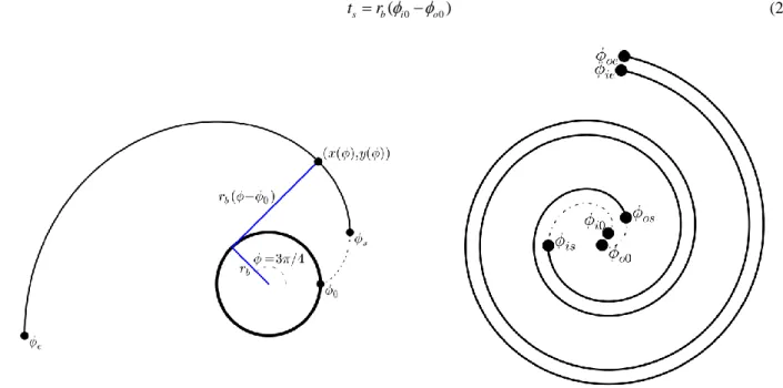
Fundamentally, the scroll compressor geometry is formed of involutes of a circle. The involute of a circle is the line that would be formed if you were to “unwrap” a circle with radius rb. Figure 1 shows what an involute of a circle
looks like. The coordinates of a point on the involute can be given by
0 0 cos ( ) sin sin ( ) cos b b x r y r (1)if the origin is taken to be the center of the base circle. While the mathematical curve for the involute is defined between involute angles of
0(on the base circle) and
e(at the end of the scroll wrap), for the actual scroll wrap, therelevant part is for between
sand
e. The part of the involute between
0and
sdoes not exist because in this region the geometry of the scroll wrap is governed by the discharge geometry.1371, Page 2
The scroll compressor is formed of two scroll wraps, each of which is formed of two scroll involutes. Typically one of the scrolls is fixed while the other orbits around it, creating the compression pockets. For the fixed scroll wrap, the two involutes are unwrapped from the same base circle, but they have different initial angles. The subscripts beginning with i refer to the “inner” involute and those beginning with o refer to the “outer” involute. The thickness of the scroll wrap can be given by
0 0
( )
s b i o
t r
(2)Figure 1: One Involute Figure 2: Two involutes forming the fixed scroll
The fixed scroll is then mated with the orbiting scroll, which has the same shape, but is mirrored through the origin and shifted by the orbiting radius. When the two scroll wraps are put together, a set of pockets are formed between the scroll wraps, as shown in Figure 3.
Figure 3: Pockets over the course of one rotation (θ=0, π/2, π, 3π/2)
The calculation of the volumes of the chambers over the course of a rotation are quite complicated. Details of these calculations are beyond the scope of this paper, but the full derivations are presented in Bell (2011), including the most comprehensive treatment of forces, moments and centroids to date.
1371, Page 3
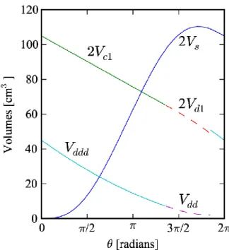
Figure 4: Volumes over one revolution
The displacement of the compressor is given by the size of the pocket that is pinched off after one rotation (c1 plus c2 from frame 1 of Figure 3). The displacement of the compressor is given by
0 0
2 3 2
disp s b o ie i o
V h r r (3)
and the volume ratio of the compressor is given by:
0 0 , 0 0 3 2 2 2 3 disp ie i o ratio c d os i o V V V (4)
which is the ratio of the displacement ratio of the compressor to the volume of the compression chamber right at the point where the compression pocket opens up to the discharge region. Typically the volume ratio is selected as the result of an optimization that combines material costs and compressor performance, but for the purposes here, we can assume that the volume ratio is known.
2.2 Derived Terms
If the volume ratio and displacement of the compressor are known, it is then possible to determine the scroll compressor geometry in order to match the desired volume ratio and displacement. A number of different sets of constraints on the scroll geometry are possible, but the constraints employed here are that the volume ratio, displacement, and the thickness of the scroll wrap are fixed.
The orbiting radius of the orbiting scroll is given by
o b s
r r
t (5)and if the displacement Vdisp, volume ratio Vratio and thickness of the scroll wraps ts are imposed, then there are three
1371, Page 4
Two further constraints are needed on the scroll geometry in order to fix the rest of the scroll geometry. Either ϕo0or ϕi0 is a free variable, the other being fixed by the scroll wrap thickness for a given base circle radius. Increasing
the value of ϕi0 just rotates the scroll wrap, so for simplicity, ϕi0 is set to zero. The value of ϕos is set to 0.3 radians.
Therefore, with the additional constraints imposed here, there remains just one free variable, which can either be taken to be the scroll wrap height hs or the base circle radius rb, and here the base circle radius was taken as the free
variable with the height adjusted to meet the displacement constraint. A method is presented in the next section to optimize the selection of the base circle radius.
With these constraints, it is possible to obtain an analytic solution for the relevant scroll wrap parameters. The outer involute initial angle is then given by
0 /
o ts rb
(6)and after some algebra and simplification, the height of the scroll wrap is given by
2 0 0 2 ( )(2 3 ) disp s b ratio o os o V h r V (7)
and the ending angle of the scroll is given by
0 2 0 3 2 4 ( ) disp o ie s b o V h r (8)
where both the fixed and orbiting scrolls have the same ending angle. If another set of constraints is desired, it is possible to use a non-linear solver to obtain the scroll wrap geometry.
For the same volume ratio, scroll wrap thickness and displacement, the larger rb is, the smaller hs must be to
maintain the same displacement, volume ratio and scroll wrap thickness. This yields a family of solutions from a very narrow cylinder to a “pancake” scroll design. Selected members of this family are shown in Figure 5. All scroll wraps are plotted at the same scale.
Figure 5: Family of scroll wraps for a volume ratio of 2.7, displacement of 104.8 cm3, and wrap thickness of 4.66 mm
3. DERIVATION OF OPTIMAL BASE CIRCLE RADIUS
As shown in the previous section, for a given volume ratio, displacement, and scroll wrap thickness, a family of different scroll wraps can be obtained. The range of scroll wraps, from a narrow cylinder to a pancake scroll, offer different performance due to the variation in the leakage rates. It is therefore useful to develop a simple model for the leakage terms in order get a first guess for the optimal scroll wrap geometry from a leakage standpoint. In the
1371, Page 5
above analysis, the base circle radius rb was a free variable, but the model presented here can predict the optimalbase circle radius with reasonable accuracy.
To begin the analysis, it is first assumed that some portion of the scroll wrap does not contribute to radial leakage. This can be understood by considering the suction chamber. Over the course of the first rotation, the outermost conjugate point moves 2π radians towards the center of the compressor. Radial area between the suction chamber and the suction area does not contribute to leakage since there is effectively no pressure difference to drive the flow. Therefore, an effective ending angle of the scroll wrap is defined by
* ie ie
(9)
which removes the contribution of half of the suction chamber since over the course of one rotation, the mean conjugate angle that divides the suction chamber and the compression chamber is the inner ending angle minus a half rotation or π radians. The same argument is employed for the inner starting angle in the discharge region. Once the discharge region has equalized in pressure the radial leakage area no longer contributes to leakage. Therefore in the discharge region, another π radians are removed from the scroll involute, yielding an effective inner involute starting angle of
* is is
(10)
which removes the contribution from the portion of the rotation where the discharge region is equalized in pressure. Thus the total radial leakage area based on the inner involutes of the fixed and orbiting scrolls can be given by
* * * 0 2 ie ( ) is radial radial b i A r d
(11) which yields * 2 * 2 * ( ) ( ) 2 2 2 ie is radial b radial A r (12)because the inner initial angle ϕi0 was fixed at 0 in order to derive the involute parameters.
The effective flank area is determined by the number of flank contact points in existence over the course of a rotation. The mean total number of flank contact points is given by
2 2 ie is flank N (13)
and the flank leakage flow area for each contact point can be given by hsδflank, thus the total flank leakage area is
given by
*
flank flank s flank
A F h N (14)
where F is a flow adjustment parameter. For a given flow area and pressure difference, more flow will go through the flank leakage. This can be understood by considering the hydraulic diameters of the leakage paths. In the radial leakage the hydraulic diameter is always twice the gap width, while for the flank leakage the conformal contact results in a hydraulic diameter that increases sharply away from the throat of the leakage path. The ratio of flank to radial frictional leakage mass fluxes is approximated from the mass flow correction terms, and is given by a value for F of 3. This value was slightly tuned in order to better fit the results from the optimization carried out on the Liquid-Flooded Ericsson Cycle compressor (Bell, 2011) for a volume ratio of 2.7. In practice, the value of this ratio is dependent on the thickness of the scroll wrap and the system operating parameters, but since the purpose of this paper is to derive a guess value for detailed optimization, this value is sufficiently accurate. Thus the total effective leakage is given by
* * *
total radial flank
1371, Page 6
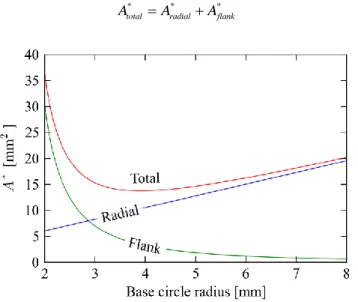
and the results for the effective leakage areas as a function of base circle radius for a volume ratio of 2.7 and displacement of 104.8 cm3 are shown in Figure 6. The effective radial leakage increases quasi-linearly with the base circle radius, while the effective flank leakage decreases with the base circle radius. Under these constraints the sum of the two terms yields a minimum effective leakage area at a base circle radius of 3.91 mm.* * *
total radial flank
A A A (16)
Figure 6: Effective flank and radial leakage areas for compressor with volume ratio of 2.7, displacement of 104.8 cm3, scroll thickness of 4.66 mm
A numerical minimization routine can be employed to determine the optimal base circle radius that minimizes
Atotal *
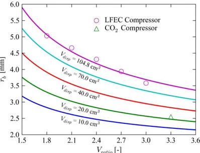
over a range of displacement and volume ratios for a fixed scroll wrap width of 4.66 mm. Both flank and radial leakage gap widths are set to 12 µm. The results of this analysis are shown in Figure 7. The optimal base circle radii obtained from the detailed compressor modeling for the Liquid-Flooded Ericsson Cycle and the Liquid-Flooded CO2 analyses (Bell, 2011) are also overlaid in order to demonstrate the effectiveness of this method for calculating an approximate optimal base circle radius. While both of these sets of optimal geometry are based on a liquid-flooded compressor, it is interesting to note that their optimal base circle radii follow closely with the model presented here. The Python code required to carry out the optimization is listed as the appendix.
It is straightforward to generate a similar plot for a different scroll wrap thickness. These results show that for a given displacement, as the volume ratio increases, the optimal base circle radius decreases. Furthermore, for a given volume ratio, as the displacement is increased, the optimal base circle radius increases. This chart can be generally employed in the design of scroll wraps, whether for flooded or dry compression applications. The inclusion of geometrically-dependent mechanical losses and scroll wrap manufacturing cost would result in different optimal scroll wrap geometry.
1371, Page 7
Figure 7: Optimal base circle radius as a function of displacement and volume ratio for a scroll with thickness 4.66 mm
CONCLUSIONS
A method for the calculation of an optimal base circle radius has been presented that allows for a means of
predicting with good accuracy the base circle radius of the scroll compressor that will minimize the leakage losses. This method can be used as a starting point for further optimization that includes the effects of mechanical losses which are also strongly dependent on the scroll wrap geometry.
ACKNOWLEDGEMENTS
The work in this paper is adapted from the Purdue University PhD. Thesis entitled Theoretical and Experimental
Analysis of Liquid Flooded Compression in Scroll Compressors by this author, published in 2011. Full-text:
http://docs.lib.purdue.edu/herrick/2/
NOMENCLATURE
VariablesA m2 Area
F - Flow correction parameter
hs m Scroll height
N - Number of
rb m Base circle radius
ro m Orbiting Radius
ts m Scroll thickness
x m x-Coordinate
y m y-Coordinate
ϕ* rad Effective involute angle
ϕ rad Involute angle
δ m Gap width
Vdisp m 3
Displacement Volume
Vratio - Volume ratio
Subscripts 0 Initial s Starting e Ending i0 Inner initial is Inner starting ie Inner ending o0 Outer initial os Outer starting oe Outer ending
1371, Page 8
REFERENCES
Bell, I., 2011. Theoretical and Experimental Analysis of Liquid Flooded Compression in Scroll Compressors. Ph.D. thesis, Purdue University. Full-text: http://docs.lib.purdue.edu/herrick/2/
Blunier, B.; Cirrincione, G.; Hervé, Y. & Miraoui, A., 2009, A new analytical and dynamical model of a scroll
compressor with experimental validation, International Journal of Refrigeration, 32, 874-891.
Bush, J. W. & Beagle, W. P., 1992, Derivation of a General Relation Governing the Conjugacy of Scroll
Profiles,1992 International Compressor Engineering Conference at Purdue University, 1079-1087.
Gravesen, J. & Henriksen, C., 2001, The Geometry of the Scroll Compressor, SIAM Review 43(1), 113-126. Morishita, E. & Sugihara, M., 1984, Scroll Compressor Analytical Model,1984 International Compressor
Engineering Conference at Purdue University, 487.
Wang, B.; Li, X. & Shi, W., 2005, A general geometrical model of scroll compressors based on discretional initial
angles of involute, International Journal of Refrigeration 28, 958-966.
APPENDIX
This example is written in Python. Requires scipy and numpy packages. When this code is run, it should yield a base circle radius of 3.915 mm.
from scipy.optimize import fmin #Multi-dimensional minimization routine
import numpy as np #Python matrix math package
from math import pi
def OptimalRb(Vratio,Vdisp,t,phi_os=0.3,F=3):
def OBJECTIVE(rb):
phi_i0=0.0
phi_is=np.pi delta=12e-6
phi_o0=phi_i0-t/rb
hs=(Vdisp)/(rb**2*2*pi*Vratio*(pi+phi_o0)*(2*phi_os+3*pi-phi_o0))
phi_ie=Vdisp/(4*pi*hs*rb**2*(pi+phi_o0))+(3*pi+phi_o0)/2.0
A_radial=2*delta*rb*((phi_ie-np.pi)**2/2-(phi_is+np.pi)**2/2-phi_i0*(phi_ie-phi_is-2*np.pi))*1e6
Nfl=(phi_ie-phi_is)/(2*pi)
A_flank=2*Nfl*delta*hs*1e6*F
return A_flank+A_radial
return fmin(OBJECTIVE,0.003,ftol=1e-12)
if __name__=='__main__':
rb=OptimalRb(1.8,40e-6,0.00466)