Design Optimization of Synchronous Reluctance
Machines for Railway Traction Application
Including Assembly Process Constraints
E. Kuci, F. Henrotte, C. Geuzaine, B. Dehez, C. De Gr´eef, C. Vers`ele, and C. Friebel
Abstract—This paper presents the coupled electro-mechanical design of a synchronous reluctance machine. The purpose of the study is to decide whether such motor could sub-stitute usual induction machines in railway traction applications. Reluctance machines are indeed competitive for applications requiring high efficiency at low cost. However, it is a challenging task to find design solutions that ensure structural integrity of the motor without compromising its overall performance, in particular in the presence of optimized flux barriers in the rotor. The design strategy presented in this paper is a combined electromagnetic and structural optimization, the latter accounting not only for the centrifugal force but also for the overstress due to manufacturing.
Index Terms—Synchronous reluctance machines, finite ele-ment analysis, shrink-fitting, multiphysical optimization, contact model, multiple operating speeds
I. INTRODUCTION
Synchronous reluctance machines can be traced back to their invention by Kostko in 1923, [1]. However, they did not find widespread use as motors until the late 1970s because of the complexity of the power electronics control they require. In recent years, synchronous reluctance motors have been receiving increasing interest in industry as well as in automotive applications. When compared to induction machines and permanent magnet synchronous machines of the same power rating, reluctance machines can provide similar performances, with no expensive copper bars or rare-earth magnets. Because of their robustness and efficiency over a wide speed range, they are a valuable alternative to induction and permanent magnet machines in a variety of applications, including hybrid and electric vehicles as well as traction applications [2]–[4].
Several multi-physics approaches have been proposed over the last decade [5]–[11] to achieve motor designs with high electromagnetic performances, satisfying requirements E. Kuci and C. Friebel are with Centre de recherche en a´eronautique
(Cenaero), Gosselies, Belgium (e-mail: erin.kuci@cenaero.be,
christophe.friebel@cenaero.be).
C. Geuzaine and F. Henrotte are with Universit´e de Li`ege (ULi`ege), Li`ege, Belgium (e-mail: cgeuzaine@uliege.be, francois.henrotte@uliege.be).
B. Dehez and C. De Gr´eef are with Universit´e catholique
de Louvain (UCLouvain), Louvain-la-Neuve, Belgium (e-mail:
bruno.dehez@uclouvain.be, christophe.degreef@uclouvain.be).
C. Vers`ele is with Alstom Belgium, Charleroi, Belgium (e-mail: christophe.andre.versele@alstomgroup.com).
on the rotor integrity and ensuring eventually lifelong relia-bility. Because operating conditions of traction motors vary considerably, such multidisciplinary analyses are preferably conducted over the drive cycle; see for instance [12] or [13]. In practice, many studies are focused on the magnetic aspects of the design, and the mechanical dimensioning only considers the effect of centrifugal forces on the rotor structure [14], [15], and on the fatigue life. To the best of our knowledge, only few studies have been reported that take the overstress resulting from the assembly process into account. The level of torque ripple is a major concern in reluctance machine design. It can be lowered by rotor skewing [16], or by an appropriate choice of the number and shape of flux-barriers according to the number of stator slots [17]. More recently, flux- and end-barrier geometries [18], as well as axially and transversally laminated rotors (see [19]–[21]) have also been investigated. Despite the higher saliency ratio and rigid structure of axially laminated rotors, the lowered level of iron losses, along with a simplified manufacturing process, make transversally laminated rotors a preferable alternative in many automotive applications; see for instance [16], [22].
Usually, electrical motor cores are manufactured by stamping or laser cutting steel laminations. Stamped lami-nations have sometimes to undergo a heat treatment process to stabilize their electromagnetic, thermal, and mechanical properties, and they are then stacked to form rotor cores. The rotor assembly is achieved when the shaft is fitted into the rotor core. The fitting operation is essential to ensure reliable motor operation and a correct transmission of torque to the external load. Improper fitting may lead to rotor core loosening during motor operation. Rotor assembly by shrinkage of laminations onto the shaft induces however significant mechanical stresses in the laminations [23], which increase with the interference (i.e. the difference between the shaft diameter and the inner diameter of the laminations before shrink-fitting). If the interference value is too large, the laminations may plasticize in the vicinity of the shaft during assembly, which is not desirable.
The use of solid rotor structures [20], and more re-cently the use of external rotor sleeves [10], as well as dual-state soft magnetic materials [24] and high strength soft magnetic materials [5], [7], [11] are among the most successful approaches overcoming the structural limitations of synchronous machines when applied in variable speed
X Z Tangential Ribs
Radial Ribs
Rotor
Shaft Flux barrier
Fig. 1. Lamination of a synchronous reluctance machine with flux-barriers, including radial as well as tangential iron bridges (ribs).
applications. Although all these methods relieve the me-chanical stress experienced by the iron bridges, only the last approach does not require any particular manufacturing process since it makes use of available off-the-shelf materials. Moreover, a solid rotor structure would drastically limit the machine performance due to the high rotor losses, while the rotor with an external sleeve inevitably increases the physical airgap, and dual-state materials are not an off-the-shelf products, leading to high costs and low availability. In these approaches the electromagnetic design is followed by a proper mechanical design, mainly based on the centrifugal force acting on the rotor structure, through a finite element (FE)-based optimization. This approach has shown to be beneficial in view of the necessary computational effort as well as the performance of the final solution.
The rotor integrity of modern synchronous reluctance machines is highly dependent on the so-called iron bridges (also known as “ribs”)—see Fig. 1. As the speed increases these bridges are made to be wider for the sake of the rotor robustness but at the cost of a reduction in torque and power factor. Several attempts have been made in order to identify guidelines based on analytical rules to design the iron bridge dimensions [6], [25]. However, such analytical models cannot predict the subdivision between the tangential and radial ribs and the positions of the latter along the flux-barrier. Regarding the latter, it has been shown that the position of the radial ribs plays a key role in the minimization of the maximum stress. However such results are obtained via a parametric study which obviously does not take into account the interaction of all rotor parameters on the struc-tural performances. The mechanical models implemented in previous studies model the behavior of the laminations under the effect of centrifugal loading resulting from the rotation of the rotor around its axis. However, these models assume a virgin initial state of stress in the laminations. The overstress resulting from the assembly process is not taken into account accurately, which leads to a current lack of accuracy of current models suffer from a lack of accuracy.
The purpose of this paper is twofold. On the one hand we want to confirm the potential of reluctance machines as
competitive substitutes for induction machines, in terms of average torque level and mechanical robustness, by replacing the rotor core of an existing induction machine used in a railway application. On the other hand, we want to improve the mechanical model by including the stresses resulting from the manufacturing process of the rotor core, submitted to a centrifugal loading. For the sake of rapid prototyping, we consider only a few operating points (speeds) rather than a time-consuming fatigue life analysis. We adopt a FE-based optimization and divide the design procedure in electromagnetic performance and proper mechanical design. The paper is organized as follows. The parameterization of the rotor is discussed in Section II. Section III deals with the electromagnetic modeling, while the assembly process model is discussed in Section IV. In Section V, the joint electro-mechanical optimization is applied to the design op-timization of the synchronous reluctance machine rotor.
II. PARAMETERIZATION OF THEFLUX-BARRIERS
Rotor laminations with Joukowski type flux-barriers (FB) are investigated in the present work. In order to prevent the optimizer from testing sets of parameters corresponding to erroneous geometries, i.e., geometries with intersecting flux barriers, an indirect parameterization is adopted that ensures non-intersecting constraints are always fulfilled [26]. Basi-cally, flux-barrier positions and thicknesses are determined by a number of constructive geometrical points that cannot meet. The idea of the indirect parametrization is to create a network of virtual springs that connect these constructive points in order to repel them from each other. The spring stiffnesses are the new design parameters. An advantage of this method is that all design parameters are of the same nature (whereas geometrical parameters can be lengths or angles, see [2]), which basically acts as an implicit normalization of the design space.
III. MAGNETICMODEL
For the purposes of the optimization at hand, the electro-magnetic performance of the motor can be evaluated with satisfying accuracy under a quasi-static assumption. This means that stator windings are supplied with the prescribed three-phase currents, and the simulation is done for a series of equidistant rotor positions over one pole pitch, as a suc-cession of static computations. Eddy currents and magnetic losses in the laminations, which are so disregarded, can be estimated a posteriori as a post-processing step if necessary. The quasi-static assumption is customary in synchronous machine models, and particularly helpful in the context of an optimization, because the magnetic model needs be evaluated a large number of times. The electromagnetic symmetries are also exploited to simulate only a quarter of the machine by means of appropriate periodicity boundary conditions.
The finite element model takes the nonlinear magnetic behavior of the stator and rotor laminations into account. The used anhysteretic saturation curve is that of a M400-50A steel grade, and the non linear finite element problem is
solved thanks to a Newton-Raphson method. The saturation curve can be modified locally (e.g. in the iron bridges where cut-edge effects are not negligible) to account for the demagnetization effects due to manufacturing, [27].
The torque is computed thanks to the Maxwell stress ten-sor in the airgap, where numerical errors linked to remeshing are minimized thanks to a moving band method, where the rotor and stator mesh are kept unchanged.
IV. SHRINK-FITTING UNDERCENTRIFUGALLOAD
Interference fit, more particularly shrink-fit, is extensively used to join rotor cores and shafts. In an assembly process, to achieve a shrink-fit joint between the rotor core and the shaft, either the rotor core or the shaft (or both) must be treated. This can be done by either heating the core to increase the internal diameter or cooling the shaft to reduce the external diameter. Thus, according to the fitting conditions, shrink-fit techniques can be categorized into three groups: (1) heating technique; (2) cooling technique, and (3) mixing technique, which is the combination of (1) and (2). In this paper, we adopted the first approach.
In previous studies, the mechanical design of shrink-fit set is based on either the classical Lam´e elastic solution of a thick-walled cylinder or the elastoplastic solution that is based on the yield criterion of von Mises, see for instance [6], [28], [29] or [30]–[32]. In this paper, we use a significantly more complex model, based on finite element method, than existing analytical guidelines due to the introduction of a contact condition between the shaft and the lamination.
The model takes into account the interference, (i.e. the difference between the diameter of the shaft and the inside diameter of the magnetic laminations before shrinking). It has been implemented with Morfeo [33], an in-house ex-pert software for industrial simulations, including processes simulation (eg. machining and welding) and crack analysis capabilities. The model consists of three steps: (i) heating the metal sheet to increase its diameter and compensate for interference; (ii) cooling the metal sheet in contact with the shaft; and (iii) rotating the assembly at the operating speeds. Steps (i) and (ii) correspond to the shrinking process. The stresses induced by the process are evaluated at the end of step (ii). A linear coefficient of thermal expansion was considered for step (i) based on data available in literature. The other properties of 42CrMo4 (shaft material) and M400-50A (magnetic sheets material) are extracted from literature as well.
The contact pressure and the maximum torque transmitted by the existing induction machine at the shaft-rotor interface are first studied. For these calculations, the assumption of plane strain is considered on the assembled laminations (thick laminations at the ends and clamping plates). The contact pressure along the shaft-rotor interface for a mid range shrinkage interference when the rotor is at rest and spinned at 6000 RPM is always much greater than zero, see Fig. 2. These calculations show that the laminations are still in compression on the shaft. In addition, they highlight
0 10 20 30 40 50 60 70 80 90 50 60 70 80 90 100
angular position (deg.)
con tact pr essure (MP a) Analytical (0 rpm) Analytical (6000 rpms) Finite Element (0 rpms) Finite Element (6000 rpm)
Fig. 2. Contact pressure distribution along the shaft-rotor interface for the
rotor of an induction machine at 0 rpm (continuous curves) and spinned at 6000 rpms (discontinuous curves). The difference with the solid disc approximation (constant curves) under the same shrinkage and spinning conditions is also highlited.
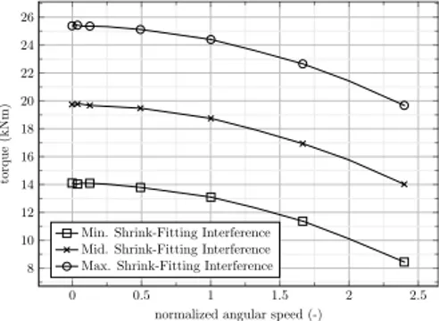
0 0.5 1 1.5 2 2.5 8 10 12 14 16 18 20 22 24 26
normalized angular speed (-)
torque
(kNm)
Min. Shrink-Fitting Interference Mid. Shrink-Fitting Interference Max. Shrink-Fitting Interference
Fig. 3. Maximum torque that can be transmitted by the induction machine
as a function of speed for different initial shrinkage interferences.
the difference with the solid disc approximation (dashed curves) under the same shrinkage and spinning conditions. As expected, the approximation of the rotor with holes by a solid rotor leads to much higher contact pressure between the rotor and shaft than observed experimentally. For the particular case of the induction machine rotor spinned at
maximum velocity of 6000 RPM, the finite element based
model predicts a minimum value contact pressure of53 MPa,
while the analytical model predicts76 Mpa. This difference
would be much greater if circular holes were replaced by flux-barriers.
From a mechanical point of view, it is essential to ensure that the torque is transmitted to the shaft. The maximum transmissible torque is evaluated by assuming a constant coefficient of friction between the rotor core lamination and the shaft. It can be observed that the transmitted torque varies only slightly with the interference value. For practical rea-sons however too high interference value may plasticize the laminations (which is, a priori, not desirable) in the vicinity of the shaft during assembly. As expected, the transmitted torque naturally decreases as the angular speed of the rotor is increased, since the contact pressure between the rotor core and the shaft is lowered.
When turning to the synchronous reluctance machine with flux barriers, the finite element model shows that the distance between the innermost barrier and the shaft-rotor interface is a critical design parameter for ensuring the integrity of the
0 10 20 30 40 50 60 70 80 90 0 20 40 60 80
angular position (deg.)
con tact pr essure (MP a)
nominal - tight band nominal - large band overspeed - tight band overspeed - large band
Fig. 4. Contact pressure of two geometrical configurations of the
flux-barriers type laminations at rest (0 RPM), as well as at maximum operating speed. The distance between the innermost barrier and the shaft-rotor interaface is doubled (resp. tight to large band).
0.4 0.5 0.6 0.7 0.8 0.9 1 0 50 100 150 200 250 300 350
normalized radial distance (-)
V on-Mises along the ribs (MP a)
nominal - tight band nominal - large band overspeed - tight band overspeed - large band yield stress limit
Fig. 5. Level of von-Mises along the radial (central) bridges for rotor
geometries with various distance between the first flux barrier and the shaft (resp. tight and large band).
structure. Reducing this parameter leads to a drastic lowering of contact pressure (close to zero) as the speed is increased, see Fig. 4. Indeed, the distortions induced by the centrifugal loading reduce the effective interference with in turns reduces the maximum transmissible torque. Improvements to the mechanical model make it possible to account for these effects and ensure the shaft to be in contact with the rotor core across the entire speed range. The numerical experiments gathered here highlight the relevance of using an accurate contact model for the design optimization of the synchronous reluctance machine.
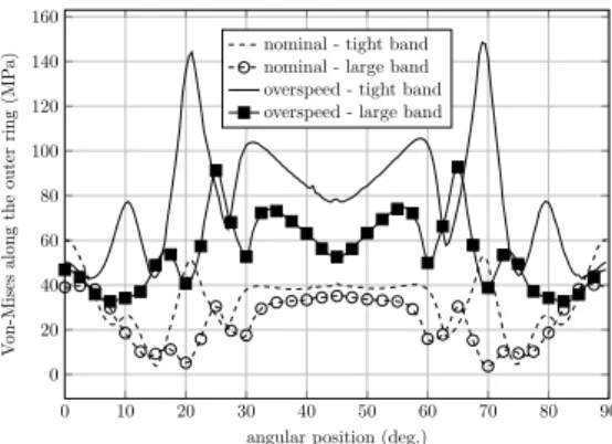
It can also be observed that central bridges experience an increase in von-Mises level when the distance between the first flux barrier and the shaft decreases, see Fig. 5. This increase in von-Mises level is even more important for the bridges closest to the shaft and exceeds a limit value considered for the design. Since decreasing this distance increases the overall level of von-Mises, this increase is also observed along the tangential ribs (close to the airgap), but still remains under the yield stress criterion, see Fig. 6.
It can be shown that the more flux barriers are used, the higher the average torque of the machine and the lower its ripple level. However, this leads to a decrease in the distance between the innermost barrier and the shaft, thus leading to a considerable decrease in contact pressure, see
0 10 20 30 40 50 60 70 80 90 0 20 40 60 80 100 120 140 160
angular position (deg.)
V on-Mises along the outer ring (MP a)
nominal - tight band nominal - large band overspeed - tight band overspeed - large band
Fig. 6. Level of von-Mises along the tangential bridges for rotor geometries with various distance between the first flux barrier and the shaft (resp. tight and large band).
0 10 20 30 40 50 60 70 80 90 30 40 50 60 70 80 90
angular position (deg.)
con tact pr essure (MP a) 2 FB - nominal 2 FB - overspeed 3 FB - nominal 3 FB - overspeed 4 FB - nominal 4 FB - overspeed
Fig. 7. Contact pressure along the interface between the shaft and the rotor core with 2, 3 and 4 flux barriers (where the distance between the innermost barrier and the shaft is reduced with the number of barriers).
Fig. 7. It also leads to an increase in the level of von-Mises along the central bridges, see Fig. 8. A compromise must therefore naturally be made between magnetic performance and mechanical integrity of the structure.
0.4 0.5 0.6 0.7 0.8 0.9 1 0 100 200 300 400
normalized radial distance (-)
V on-Mises along the ribs (MP a) 2 FB - nominal 2 FB - overspeed 3 FB - nominal 3 FB - overspeed 4 FB - nominal 4 FB - overspeed yield stress limit
Fig. 8. Level of von-Mises along the central bridges of the rotor core with
2, 3 and 4 flux barriers. The distance between the innermost barrier and the shaft is lowered with the number of flux barriers.
V. ELECTRO-MECHANICALOPTIMIZATION
The goal of the optimization is to design flux barriers in the rotor of the synchronous machine so as to achieve the same level of average torque and ripples as those in
the reference induction motor. With regard to mechanical robustness, the purpose is twofold. The level of mechanical stress (von-Mises) must be kept below acceptable limits in the most sensitive areas (central and tangential ribs). On the other hand, the contact pressure between the shaft and the rotor core must be high enough to avoid the loosening of the lamination package, and ensure torque transmission to the shaft over the whole speed range. In order to speed up the design process, an accurate life fatigue assessment is not performed, but we rather limit ourselves to two operating points: one at maximum speed (4800 rpms) and the other at overspeed (5760 rpm, which is about 20% higher than maximum speed).
The design problem is formulated as a constrained op-timization problem aiming at determining the thickness of radial and tangential bridges, based on the level of von-Mises evaluated only at these bridges. In the same way, the positioning of the innermost barrier is also determined by the stress level at a point between this barrier and the shaft interface. The design space also includes the load angle, the spring stiffnesses (geometrical parameters that define the barriers) and the number of barriers (a discrete parameter ranging from 1 to 5). From a magnetic point of view, the constraints have been chosen to match those of the reference induction machine, using the same stator in both. The stator currents and the technical limits (bounds) of the various performance functions are thus chosen to be identical to that of the reference induction machine, i.e., the target value for
the average torque is 1500 Nm with 10% ripples. For the
mechanical part, the level of von-Mises should be less than
(or equal to) 75% of the elastic limit at maximum speed
(350 MPa); whereas it is imposed to be kept lower than (or
equal to)85% of the elastic limit at overspeed. A series of
degrees of freedom have been fixed a priori: the current value
(nominal value of the induction machine,217A), fillet radii,
positioning and number of radial bridges (only 1 radial bridge per barrier), value of the interference between rotor and shaft (mid-range) for shrink-fitting model.
The computational chain is based on Gmsh [34] for the CAD model and meshing, and GetDP [35] for the nonlinear magnetostatic computation. Two further in-house software are considered. On the one hand, MORFEO [33], a finite element analysis software with processes simulation (eg. machining and welding) and crack analysis capabilities; and on the other MINAMO, an advanced optimization platform based on the use of surrogate models [36].
X Y Z FB-1 FB-2 FB-3 FB-4 FB-1 FB-2 FB-3 FB-4 O1 O2
Fig. 9. Optimized rotor geometries considering one operating speed (O1
left) and two operating speeds (O2 right).
0.4 0.5 0.6 0.7 0.8 0.9 1 0 100 200 300 400
normalized radial distance (-)
V on-Mises along the ribs (MP a) nominal - O1 nominal - O2 overspeed - O1 overspeed - O2 yield stress limit
Fig. 10. Level of von-Mises along the radial (central) bridges for rotor
geometries resulting from an optimization based on a single operating speed (O1), as well as two operating speeds (O2).
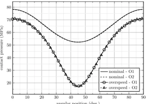
0 10 20 30 40 50 60 70 80 90 20 30 40 50 60 70 80
angular position (deg.)
con tact pr essure (MP a) nominal - O1 nominal - O2 overspeed - O1 overspeed - O2
Fig. 11. Contact pressure along the shaft-rotor interface at nominal speed
and spinned at over 20% of the maximum speed, for rotors resulting from both a single operating speed (O1) based optimization and two operating speeds (O2) optimization.
The optimization resulted in a design with four flux barri-ers, see Fig. 9. A similar result is also obtained by considering a single operating point at maximum speed. Both of them
exhibit average torque about 20% lower than the induction
machine fed with the same stator current, with less than5%
torque ripples. The differences lie mainly in the level of von-Mises along the central bridges, see Fig. 10 (the stress levels everywhere else in the rotor are well below the maximum stress criterion). The design obtained by considering a single operating frequency exceeds the yield criterion at overspeed, whereas the design considering both speeds is acceptable over the whole range of speeds, and is therefore suitable for manufacturing. For both designs, the contact pressure is above the prescribed limit at both operating speeds, see Fig. 11.
The consistency of the optimization is confirmed by obtaining the critical speeds by a simplified Jeffcott model (rotor is assumed mounted on rigid bearings with rigid disk, while the shaft is considered elastic and massless). The first
eigenfrequencypk/M is the ratio between the stiffness k of
the shaft in flexion and the disc massM . The polar moment
of inertia (stiffness) decreases much less (0.3 kgm2) than
the rotor mass (19.6 kg) when moving from the induction machine to the optimized synchronous machine. This results altogether in an increase of the first natural frequency. Since the reference induction machine had no vibration problems,
0 0.2 0.4 0.6 0.8 1 0.2 0.4 0.6 0.8 1
normalized angular speed (-)
normalized
torque
(-)
Induction machine Synchronous machine (current limited) Synchronous machine (maximum torque)
0 0.2 0.4 0.6 0.8 1 0.4 0.6 0.8 1 1.2 1.4 1.6
normalized angular speed (-)
normalized
curren
t
(-)
Induction machine Synchronous machine (current limited) Synchronous machine (maximum torque)
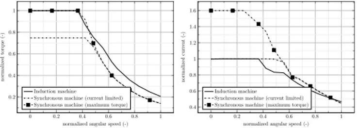
Fig. 12. Normalized torque- (resp. voltage)-speed characteristic of the
reference induction machine and the optimized synchronous machine, both operating in traction mode, simulated (i) by limiting the norm of the stator current, and (ii) by increasing this current so as to reach the same level of torque as the induction machine.
the optimized synchronous machine should not have any either.
The optimized reluctance machine is also compared to the induction machine through the torque-speed curve (see Fig. 12 for the case of traction operation where the data are normalized to the induction machine). The idea is to make the best use of the reluctance machine while imposing a limit on the current norm (thermal limitation). This yields two cases based on the level of current norm: (i) identical to that of the induction machine, and (ii) a higher one (by ≈ 62%) in order to obtain a level of torque similar to that of the induction machine without defluxing). In the phase without defluxing (MTPA), more current must be fed to the synchronous machine to obtain the same level of torque as the induction machine due to the lowered power factor, while in defluxing phase (MTPV) torque decreases as the square of inverse of speed instead of the inverse of speed.
VI. CONCLUDING REMARKS
This paper has studied the tight interplay between me-chanical and magnetic issues when designing a reluctance motor rotor with magnetic flux barriers. We have shown in particular the strong impact of mechanical stresses due to the assembly process on the structural integrity of the rotor, and a contact model based on finite element calculations has been implemented to cover that issue in the optimisation. It has also been demonstrated that several operating points should be considered in the optimization to reach a design acceptable over the full range of working points of the motor. Eventually, our optimisation process delivered a valid design, achieving the expected torque levels for the given supply conditions, and ensuring structural integrity regarding centrifugal forces and torque transmission to the shaft.
VII. ACKNOWLEDGMENT
This work was supported in part by the Walloon Region of Belgium under grant PIT 7706 Traction2020. The present research benefited from computational resources made avail-able on the Tier-1 supercomputer of the F´ed´eration Wallonie-Bruxelles, infrastructure funded by the Walloon Region under the grant agreement no 1117545.
REFERENCES
[1] J. Kostko, “Polyphase reaction synchronous motors,” Journal of the American Institute of Electrical Engineers, vol. 42, no. 11, pp. 1162– 1168, 1923.
[2] M. Di Nardo, G. L. Calzo, M. Galea, and C. Gerada, “Design optimization of a high-speed synchronous reluctance machine,” IEEE Transactions on Industry Applications, vol. 54, no. 1, pp. 233–243, 2017.
[3] A. Boglietti, A. Cavagnino, M. Pastorelli, D. Staton, and A. Vagati, “Thermal analysis of induction and synchronous reluctance motors,” IEEE Transactions on Industry Applications, vol. 42, no. 3, pp. 675– 680, 2006.
[4] A. Fratta, G. Toglia, A. Vagati, and F. Villata, “Ripple evaluation of high-performance synchronous reluctance machines,” IEEE Industry applications magazine, vol. 1, no. 4, pp. 14–22, 1995.
[5] I. Tanaka, H. Nitomi, K. Imanishi, K. Okamura, and H. Yashiki, “Application of high-strength nonoriented electrical steel to interior permanent magnet synchronous motor,” IEEE Transactions on Mag-netics, vol. 49, no. 6, pp. 2997–3001, 2012.
[6] M. Barcaro, G. Meneghetti, and N. Bianchi, “Structural analysis of the interior pm rotor considering both static and fatigue loading,” IEEE Transactions on Industry Applications, vol. 50, no. 1, pp. 253–260, 2013.
[7] M. Palmieri, M. Perta, F. Cupertino, and G. Pellegrino, “High-speed scalability of synchronous reluctance machines considering different lamination materials,” in IECON 2014-40th Annual Conference of the
IEEE Industrial Electronics Society. IEEE, 2014, pp. 614–620.
[8] M. Di Nardo, M. Galea, C. Gerada, M. Palmieri, and F. Cupertino, “Multi-physics optimization strategies for high speed synchronous reluctance machines,” in 2015 IEEE Energy Conversion Congress and
Exposition (ECCE). IEEE, 2015, pp. 2813–2820.
[9] M. Di Nardo, M. Galea, C. Gerada, M. Palmieri, F. Cupertino, and S. Mebarki, “Comparison of multi-physics optimization methods for high speed synchrnous reluctance machines,” in IECON 2015-41st Annual Conference of the IEEE Industrial Electronics Society. IEEE, 2015, pp. 002 771–002 776.
[10] P. B. Reddy, K. Grace, and A. El-Refaie, “Conceptual design of sleeve rotor synchronous reluctance motor for traction applications,” IET Electric Power Applications, vol. 10, no. 5, pp. 368–374, 2016. [11] M. Palmieri, M. Perta, and F. Cupertino, “Design of a 50.000-r/min
synchronous reluctance machine for an aeronautic diesel engine com-pressor,” IEEE Transactions on Industry Applications, vol. 52, no. 5, pp. 3831–3838, 2016.
[12] A. Fatemi, N. A. Demerdash, T. W. Nehl, and D. M. Ionel, “Large-scale design optimization of pm machines over a target operating cycle,” IEEE Transactions on Industry Applications, vol. 52, no. 5, pp. 3772– 3782, 2016.
[13] E. Sikanen, J. Nerg, J. E. Heikkinen, M. G. Tehrani, and J. Sopanen, “Fatigue life calculation procedure for the rotor of an embedded magnet traction motor taking into account thermomechanical loads,” Mechanical Systems and Signal Processing, vol. 111, pp. 36–46, 2018. [14] P. Lindh, M. G. Tehrani, T. Lindh, J.-H. Montonen, J. Pyrh¨onen, J. T. Sopanen, M. Niemel¨a, Y. Alexandrova, P. Immonen, L. Aarniovuori et al., “Multidisciplinary design of a permanent-magnet traction motor for a hybrid bus taking the load cycle into account,” IEEE Transactions on Industrial Electronics, vol. 63, no. 6, pp. 3397–3408, 2016. [15] F. Chai, Y. Li, P. Liang, and Y. Pei, “Calculation of the maximum
me-chanical stress on the rotor of interior permanent-magnet synchronous motors,” IEEE Transactions on Industrial Electronics, vol. 63, no. 6, pp. 3420–3432, 2016.
[16] D. Staton, T. Miller, and S. Wood, “Maximising the saliency ratio of the synchronous reluctance motor,” in IEE Proceedings B (Electric
Power Applications), vol. 140, no. 4. IET, 1993, pp. 249–259.
[17] A. Vagati, M. Pastorelli, G. Francheschini, and S. C. Petrache, “Design of low-torque-ripple synchronous reluctance motors,” IEEE Transac-tions on Industry ApplicaTransac-tions, vol. 34, no. 4, pp. 758–765, 1998. [18] N. Bianchi, M. Degano, and E. Fornasiero, “Sensitivity analysis of
torque ripple reduction of synchronous reluctance and interior pm motors,” IEEE Transactions on Industry Applications, vol. 51, no. 1, pp. 187–195, 2014.
[19] H. Hofmann and S. R. Sanders, “High-speed synchronous reluctance machine with minimized rotor losses,” IEEE Transactions on Industry Applications, vol. 36, no. 2, pp. 531–539, 2000.
[20] J. Ik¨aheimo, J. Kolehmainen, T. K¨ans¨akangas, V. Kivel¨a, and R. R. Moghaddam, “Synchronous high-speed reluctance machine with novel rotor construction,” IEEE Transactions on Industrial Electronics, vol. 61, no. 6, pp. 2969–2975, 2013.
[21] N. Bianchi, E. Fornasiero, and W. Soong, “Selection of pm flux linkage for maximum low-speed torque rating in a pm-assisted synchronous reluctance machine,” IEEE Transactions on Industry Applications, vol. 51, no. 5, pp. 3600–3608, 2015.
[22] M. J. Kamper, F. Van der Merwe, and S. Williamson, “Direct finite element design optimisation of the cageless reluctance synchronous machine,” IEEE Transactions on Energy Conversion, vol. 11, no. 3, pp. 547–555, 1996.
[23] W. Tong, Mechanical design of electric motors. CRC press, 2014.
[24] A. M. El-Refaie and T. M. Jahns, “Application of bi-state magnetic material to an automotive ipm starter/alternator machine,” IEEE Trans-actions on Energy Conversion, vol. 20, no. 1, pp. 71–79, 2005. [25] A. Binder, T. Schneider, and M. Klohr, “Fixation of buried and
surface-mounted magnets in high-speed permanent-magnet synchronous ma-chines,” IEEE Transactions on Industry Applications, vol. 42, no. 4, pp. 1031–1037, 2006.
[26] C. De Greef, V. Kluyskens, F. Henrotte, C. Geuzaine, and B. De-hez, “Impact of flux barriers type and parameterization in reluctance machine torque optimization,” in Conference Record of the 19th International Symposium on Electromagnetic Fields in Mechatronics,
vol. 3. IEEE, 2019, pp. 1193–1200.
[27] M. Bali, H. D. Gersem, and A. Muetze, “Finite-Element Modeling of Magnetic Material Degradation Due to Punching,” IEEE Transactions on Magnetics, vol. 50, no. 2, pp. 745–748, Feb. 2014.
[28] O. Horger and C. Nelson, “Design of press-and shrink-fitted assem-blies,” ASME J. Appl. Mech., vol. 59, pp. A–183, 1937.
[29] X.-L. Gao and S. N. Atluri, “An elasto-plastic analytical solution for the shrink-fit problem with a thin strain-hardening hub and an elastic solid shaft,” Mathematics and Mechanics of Solids, vol. 2, no. 3, pp. 335–349, 1997.
[30] A. ¨Ozel, S¸. Temiz, M. D. Aydin, and S. S¸en, “Stress analysis of
shrink-fitted joints for various fit forms via finite element method,” Materials & design, vol. 26, no. 4, pp. 281–289, 2005.
[31] B. J. Hamrock, S. R. Schmid, and B. O. Jacobson, Fundamentals of
machine elements. McGraw-Hill Professional, 2004.
[32] W. B. Bickford, Advanced mechanics of materials. Addison-Wesley,
1998.
[33] “Morfeo version 3.1.0 (2019), a Manufacturing ORiented Finite Ele-ment sOftware, Cenaero, Belgium,” Web page: http://www.cenaero.be. [34] C. Geuzaine and J.-F. Remacle, “Gmsh: A 3-d finite element mesh generator with built-in pre-and post-processing facilities,” International journal for numerical methods in engineering, vol. 79, no. 11, pp. 1309–1331, 2009.
[35] P. Dular, C. Geuzaine, F. Henrotte, and W. Legros, “A general envi-ronment for the treatment of discrete problems and its application to the finite element method,” IEEE Transactions on Magnetics, vol. 34, no. 5, pp. 3395–3398, 1998.
[36] C. Sainvitu, V. Iliopoulou, and I. Lepot, “Global optimization with expensive functions-sample turbomachinery design application,” pp. 499–509, 2010.
VIII. BIOGRAPHIES
Erin Kuci completed his master degree in eletrical engineering and his Ph.D., respectively in 2013 and 2018, both at University of Li`ege in Belgium. He is currently a research engineer at the Centre de recherche en a´eronautique (Cenaero), Gosselies. His main research interests include machine learning techniques, the design and optimization of electromagnetic devices, and in particular electrical machines and actuators. He is also the co-author of the optimization package Conveks.
Franc¸ois Henrotte completed his Engineering Degree in 1991 and his PhD in 2000, both at the University of Li`ege in Belgium. He then spent 4 years at the Katholieke Universiteit Leuven and 6 years at the Institut f ¨ur Elektrische Maschinen in Aachen, Germany, and is now with the UCL and the ULi`ege. Developer in the open-source packages Gmsh, GetDP, Onelab, he has also developed skills in the multiphysics simulation of electrical machine and electrical drive. His main interests are finite element analysis, numerical modeling, electromechanical coupling, material properties (hysteresis, iron losses, superconductors), applied mathematics (differential geometry, alge-braic topology, convex analysis, dual analysis, energy methods), multiscale methods, sensitivity and optimization.
Christophe Geuzaine Christophe Geuzaine received the master’s degree in electrical engineering and the Ph.D. degree from the Universit´e de Li`ege (ULi`ege), Li`ege, Belgium, in 1996 and 2001, respectively. After post-doctoral positions at the California Institute of Technology and with the Belgian National Science Foundation, he became an assistant professor of Mathematics at Case Western Reserve University in 2005. In 2007 he came back to the University of Li`ege, where he is now full professor in the department of Electrical Engineering and Computer Science. He is the founder and head of the Applied and Computational Electromagnetics research group within the Montefiore Institute. His research interests encom-pass modeling, analysis, algorithm development, and simulation for problems arising in various areas of engineering and science, and in particular electrical machines and actuators. He has authored numerous papers in the fields of scientific computing and is the co-creator of the popular open source mesh generator Gmsh and the multi-physics finite element solver GetDP.
Bruno Dehez (M’06-SM’17) received the master’s degree in electrome-chanical engineering and the Ph.D. degree from the Universit´e catholique de Louvain (UCLouvain), Louvain-la-Neuve, Belgium, in 1998 and 2004, respectively. He is currently a Professor with the Ecole Polytechnique de Louvain and is the Head of the Mechatronic, Electrical Energy, and Dynamic Systems Division, UCLouvain. His research interests include the design and the optimization of electromagnetic devices, and particularly of electrical machines and actuators.
Christophe De Gr´eef received the M.Sc. degree in electromechanical engi-neering in 2017, from the Universit´e Catholique de Louvain (UCLouvain), Louvain-la-Neuve, Belgium. He is currently a research assistant at the Mechatronic, Electrical Energy, and Dynamic Systems (MEED) division, UCLouvain. His research interests include the design and the optimization of electromagnetic devices, with a focus on synchronous reluctance machines and magnetic gears.
Christophe Vers`ele received the M.Sc. degree in Electrical Engineering and the Ph.D. degree in Applied Sciences from Facult´e Polytechnique de Mons, UMons, in 2007 and 2012, respectively. He is currently working in Alstom Belgium as a Traction System Enginneer. His research interests include power electronics converters and electrical motors used in railway. traction chains.
Christophe Friebel received the master’s degree in applied mathematics and the Ph.D. degree from the Universit´e Catholique de Louvain (UCLouvain), Louvain-la-Neuve, Belgium, in 2002 and 2007, respectively. He is currently a research engineer at the Centre de recherche en a´eronautique (Cenaero), Gosselies, Belgium. His research interests include the numerical modeling and simulation of manufacturing processes for metallic parts.