EXPERIMENTAL AND NUMERICAL STUDY OF NEEDLE PEENING EFFECTS IN ALUMINIUM ALLOY 2024-T3 SHEETS
JULIO ALBERTO MÉNDEZ ROMERO DÉPARTEMENT DE GÉNIE MÉCANIQUE ÉCOLE POLYTECHNIQUE DE MONTRÉAL
MÉMOIRE PRÉSENTÉ EN VUE DE L’OBTENTION DU DIPLÔME DE MAÎTRISE ÈS SCIENCES APPLIQUÉES
(GÉNIE MÉCANIQUE) FÉVRIER 2016
c
ÉCOLE POLYTECHNIQUE DE MONTRÉAL
Ce mémoire intitulé :
EXPERIMENTAL AND NUMERICAL STUDY OF NEEDLE PEENING EFFECTS IN ALUMINIUM ALLOY 2024-T3 SHEETS
présenté par : MÉNDEZ ROMERO Julio Alberto
en vue de l’obtention du diplôme de : Maîtrise ès sciences appliquées a été dûment accepté par le jury d’examen constitué de:
M. VADEAN Aurelian, Doctorat, président
M. LÉVESQUE Martin, Ph. D., membre et directeur de recherche M. GOSSELIN Frédérick, Doctorat, membre
DEDICATION
To my awesome family and friends . . . You know I love you.
ACKNOWLEDGEMENTS
I would like to galantly express my gratitude to my research supervisor, Prof. Martin Lévesque for his supervision, guidance and expertise throughout this research as well as showing me the more human side of what the academic life compasses. I would also like to thank the jury members for their time, guidance and suggestions.
I would like to acknowledge Syvlain Forgues and Brigitte Labelle from Shockform Aero-nautique Inc. for their support of this research by means of their experience, technology and infrastructure. I want to extend these thanks to the rest of their team who replied gladly to all of my questions and requests.
I wish to thank the members of the LM2 laboratory from École Polytechnique. Special thanks to Hongyan Miao, Fubin Tu, Alexandre Gariépy, and Pierre Faucheux for their help-ful advice during my research activities. I would like to thank Stéphane Étienne and Cédric Béguin for providing the equipment used for the high-speed shooting. My special thanks go to Amrita Bag, Thierry Klotz and Charles Bianchetti for helping me in the transition into the research life.
And finally, I would like to thank my friends for supporting me and encouraging me. To my family, thanks for always being there - not only these last couple years but for showing their support in whatever endeavour I partake.
RÉSUMÉ
Le grenaillage est un procédé utilisé dans l’industrie aérospatiale pour améliorer la vie en fatigue des composantes soumises à des contraintes cycliques, comme les trains d’atterrissage, les voilures d’avoin et certaines pièces de moteurs. La méthode de grenaillage la plus commune consiste à projeter des petites billes sur la surface d’une pièce pour modifier sa structure de surface. Les impacts des billes, appelées grenailles, induisent des déformations plastiques en surface, ce qui conduit à des contraintes résiduelles compressives en surface. Bien que la grenailleuse soit utilisée pour le traitement de grandes pièces, il existe des technologies pour faire le grenaillage localisé, comme le grenaillage aux aiguilles. Ce travail de recherche a eu comme objectif d’analyser en détail le comportement d’un nouveau prototype d’appareil de grenaillage à aiguilles, appelé le SPIKERTMpour en comprendre les effets sur les contraintes
résiduelles de l’alliage AA2024-T3.
L’équipement a été premièrement caractérisé en utilisant une caméra à haute vitesse pour étudier son comportement en changeant la pression d’opération. L’ensemble des images collecté a été traité par un nouvel algorithme de manipulation numérique pour quantifier la vitesse et la fréquence des impacts des aiguilles. La vitesse au moment d’impact et la fréquence des impacts ont été déterminées pour différents paramètres d’opération. Il a été conclu que la vitesse et la fréquence des impacts augmentent avec la pression. Des anomalies du comportement, dont des variations de la fréquence et la vitesse parmi les aiguilles, ont été observées.
La réponse de l’alliage AA2024-T3 au grenaillage aux aiguilles a été étudiée expérimentale-ment sur des tôles d’une épaisseur de 1.6 mm. Les tôles ont été coupées aux dimensions des bandes Almen et traitées par le SPIKER . L’alliage AA2024-T3 a été choisi car il aR
été bien étudié à l’École Polytechnique de Montréal dans la cadre de recherche de grenail-lage conventionnel. Des essais de saturation ont été réalisés pour déterminer la déflection à la saturation pour plusieurs paramètres de grenaillage. La déflection a été aussi mesurée avec l’outil standard Almen utilisé dans la vérification périodique du traitement. Comme l’aluminium n’était pas magnétiquement compatible avec l’outil Almen, la déformation des échantillons a été mesurée avec une Machine à Mesurer Tridimensionnelle (MMT). La répéta-bilité du procédé a été démontrée et la déflection au point de saturation, comme le temps de saturation, ont été obtenus. Les diamètres des indentations crées par les impacts ont été mesurés pour les différentes valeurs de pression en utilisant la photographie microscopique. Il a été déterminé que la déformation des éprouvettes et les diamètres des indentations
aug-mentent avec la pression utilisée. Le traitement des échantillons avec les mêmes paramètres de grenaillage a créé des indentations de tailles variées. Cette observation est expliquée par la variation de la vitesse des impacts détectée pendant les essais de caractérisation. L’avantage que le grenaillage aux aiguilles fournit, en comparaison aux méthodes conventionnelles, est que l’uniformité des diamètres des indentations est plus facile à atteindre, car tous les impacts sont normaux, et de même énergie. Finalement la détermination des contraintes résiduelles a été effectuée par la Diffraction Rayons-X (DRX) pour un échantillon à saturation.
Un maillage éléments finis inspiré de travaux antérieurs à Polytechnique, a été développé pour simuler le grenaillage aux aiguilles. Les paramètres obtenus pendant les essaies de caractérisation ont été utilisés dans le modèle. La première partie de l’étude s’est intéressée à comparer les diamètres des cratères prédits et mesurés expérimentalement pour un seul impact. Une bonne adéquation a été observée.
Le modèle a été utilisé pour étudier le développement des contraintes résiduelles comme con-séquence des impacts aléatoires à différentes vitesses. Le point de saturation a été déterminé en obtenant la déflection créée à partir des contraintes induites à partir de modèles devel-oppés à Polytechnique. Le profil des contraints résiduelles au point de saturation pour un des cas a été comparé aux résultats obtenus par la DRX. Le modèle a été capable de prédire les contraintes résiduelles en surface (187 MPa) très proches de celles mesurées expérimen-talement (184 MPa) . Finalement, la déflection prédite par le modèle a été comparée à celle mesurée expérimentalement pour différentes pressions d’opération. La différence maximale de déflection entre les résultats simulés et les résultats expérimentaux a été de 2% pour l’échantillon avec les contraintes résiduelles confirmées par la DRX. Une surestimation de 50% a été enregistrée pour la pression la plus faible, mais demeure entre 0.3% et le 13.2% pour les autres pressions. Comme conclusion, la méthodologie présentée prouve qu’il est possible de prédire les contraintes induites par le grenaillage aux aiguilles.
ABSTRACT
Peening of metallic components is an effective treatment used in aerospace and automotive applications to improve fatigue properties or to blend and repair localized damage. This process is typically carried out using metallic airborne media, called shot. However, different processes make use of different media, such is the case of hard, pneumatically powered needles of needle peening equipment. In order to obtain a better understanding of the effects of needle peening in the same context as shot peening, this research work had as an objective to study in detail the behavior of the needle peening equipment in order to characterize the process, design an experimental campaign to measure the effects of needle peening on AA2024-T3 and to develop and validate a Finite Element (FE) model capable of replicating the results of needle peening. The needle peening equipment prototype, called SPIKER , was developedR
by Shockform Aeronautique Inc.
The equipment was characterized by utilizing high-speed camera recording in order to study its behaviour by varying the operating pressure. The obtained collection of images was ran through a newly developed digital image algorithm, so as to quantify the needles’ velocity and frequency. The impact velocity and impact frequency were determined for different equipment operating parameters. It was concluded that both the average impact velocity and the impact frequency increase as the pressure becomes larger. Behaviour anomalies among the different needles, such as frequency and velocity variations, were brought to light; these conclusions could be of interest to the manufacturer. Ideally, all of the needles should behave as similarly as possible so as to produce a more uniform process.
The response to needle peening of AA2024-T3 in 1.6 mm thick sheet form was studied by needle peening test specimens with dimensions of an Almen strips using the SPIKER .R
AA2024-T3 was selected since it was extensively studied at École Polytechnique de Montréal as part of previous shot peening research. Saturation tests were done to determine the deflec-tion at saturadeflec-tion for different peening parameters. The specimen deflecdeflec-tion was measured using the standard Almen gauge used as part of routinary process control. Due to the alu-minium magnetic incompatibility with the Almen gauge, the deformed specimen profile was measured using a Coordinate Measuring Machine (CMM). Repeatability of the process was demonstrated and the deflection at saturation, as well as the saturation time, was obtained. The indentation diameters created by impacts for different operating pressures were measured using microscopic photography. It was determined that the specimen deformation, as well as the indentation diameter, is larger when the operating pressure increases. Treatment of the
test samples using the same peening parameters resulted in a variable indentation diameter. This is explained by the velocity variations detected during the equipment characterization. The added value that needle peening could provide to existing peening techniques is that, in principle, uniformity in the indentation diameters is easier to achieve as all impacts are normal and there is no loss of energy due to media interaction. The last experimental test was to determine the induced residual stress by means of X-ray Diffraction (XRD) for one specimen at saturation.
An FE model heavily inspired by previous shot peening modeling was developed to simulate needle peening. The parameters obtained during the characterization of the equipment were taken as boundary conditions. Initially, the case of a single impacts was studied. Good accordance between the simulated and the average experimental indentation diameters was obtained, except for the lowest pressure studied. The overestimation of the indentation diameter could stem from the method used to measure the simulated diameter. Coverage estimation, and therefore indentation diameters remain an open line of research in shot peening simulation. Using the same model, it was demonstrated that the induced stress profile changes in depth and magnitude as impact velocity increases.
Finally, the same model was used to study the development of residual stresses after multiple stochastic impacts at different velocities. Saturation was determined by obtaining the arc height created as as consequence of inducing the stresses determined by the impact model and obtaining a regression model that would best fit through the multiple simulation results. The residual stress profile at saturation for one of the scenarios was compared against the XRD results from the sample peened at the same operating pressure. The model was able to predict the surface residual stress (187 MPa) within 1.6% of the exprimental results (184 MPa). The results for the remainder of the cases studied were then compared against the deflection measured using the CMM. The maximum deflection difference between the predicted and the experimental results was of 2% for the sample for which the residual stress profile was confirmed. For the lowest air pressure, an overestimation of 50% was seen, however the difference between experimental and predicted results rests between 0.3% and 13.2% for the remainder of the cases. To conclude, the methodology presented proves that it is possible to predict the induced stresses by needle peening, which in hand can be used to predict sample deflection.
TABLE OF CONTENTS DEDICATION . . . iii ACKNOWLEDGEMENTS . . . iv RÉSUMÉ . . . v ABSTRACT . . . vii TABLE OF CONTENTS . . . ix LIST OF TABLES . . . xi
LIST OF FIGURES . . . xii
LIST OF ACRONYMS . . . xiv
LIST OF SYMBOLS . . . xv
CHAPITRE 1 INTRODUCTION . . . 1
INTRODUCTION . . . 1
1.1 Introduction to needle peening . . . 1
1.2 Problem definition . . . 2
1.3 Thesis overview . . . 3
CHAPITRE 2 LITERATURE REVIEW . . . 4
2.1 Introduction to peening . . . 4
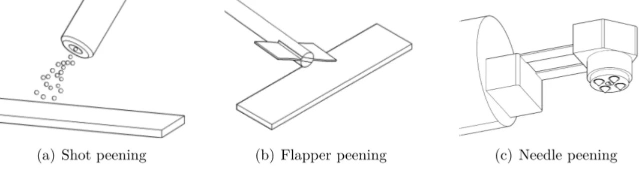
2.2 Types of portable peening technologies . . . 4
2.2.1 Shot peening . . . 4
2.2.2 Rotary flap peening . . . 5
2.2.3 Needle peening . . . 6
2.3 Mechanics of peening . . . 6
2.4 Process monitoring . . . 6
2.4.1 Almen intensity . . . 6
2.4.2 Surface coverage . . . 8
2.5.1 Shot flow characterization . . . 8
2.5.2 Residual stress . . . 9
2.5.3 Material deformation . . . 10
2.6 Analytical studies of peening results . . . 11
2.6.1 Residual stresses . . . 11
2.6.2 Material deformation and coverage . . . 12
2.7 Numerical simulations of peening effects using the FE method . . . 13
2.7.1 Dynamic impact models . . . 13
2.7.2 Material constitutive theory . . . 18
2.7.3 Peen forming . . . 19
CHAPITRE 3 PROJECT RATIONALLE AND OBJECTIVES . . . 21
CHAPITRE 4 RESEARCH METHODOLOGY . . . 23
4.1 Needle peening application on AA2024 and process characterization . . . 23
4.1.1 Equipment characterization . . . 23 4.1.2 Experimental procedures . . . 27 4.2 Numerical analysis . . . 29 4.2.1 FE impact model . . . 29 4.2.2 Specimen deflection . . . 32 CHAPITRE 5 RESULTS . . . 33
5.1 Needle peening application on AA2024 and process characterization . . . 33
5.1.1 Equipment characterization . . . 33
5.1.2 Experimental procedures . . . 36
5.2 Numerical analysis . . . 43
5.2.1 FE impact model - single impact . . . 43
5.2.2 FE impact model - multiple impacts . . . 47
CHAPITRE 6 GENERAL DISCUSSION . . . 53
CHAPITRE 7 CONCLUSION . . . 55
LIST OF TABLES
Table 4.1 FE mesh geometry . . . 30 Table 5.1 Relationship between peening pressure and measured arc height at
sat-uration AHm
s . . . 40 Table 5.2 Relationship between air pressure and impact velocity . . . 44 Table 5.3 Measured and predicted indentation diameters after single impact . . 45 Table 5.4 Arc height saturation solution for v = 1.57 mm/ms . . . . 48 Table 5.5 Predicted and measured arc height comparison . . . 51
LIST OF FIGURES
Figure 1.1 Generation of indentations by needle peening . . . 1
Figure 2.1 Typical induced stress profile after peening . . . 5
Figure 2.2 Types of portable peening equipment . . . 5
Figure 2.3 Processes of development of residual stresses . . . 7
Figure 2.4 Process to determine the intensity of peening . . . 8
Figure 2.5 Induced stresses by needle peening and shot peening in Ti6246 . . . . 10
Figure 2.6 Schematic of the principle of stress forming . . . 12
Figure 2.7 Meshing examples for two-dimensional models . . . 15
Figure 2.8 Examples of three-dimensional FE models . . . 15
Figure 2.9 Representative surface modeling proposed by Miao et al. (2009) . . . 16
Figure 4.1 Simplified representation of the needle peening equipment prototype . 23 Figure 4.2 High-speed camera recording set-up . . . 24
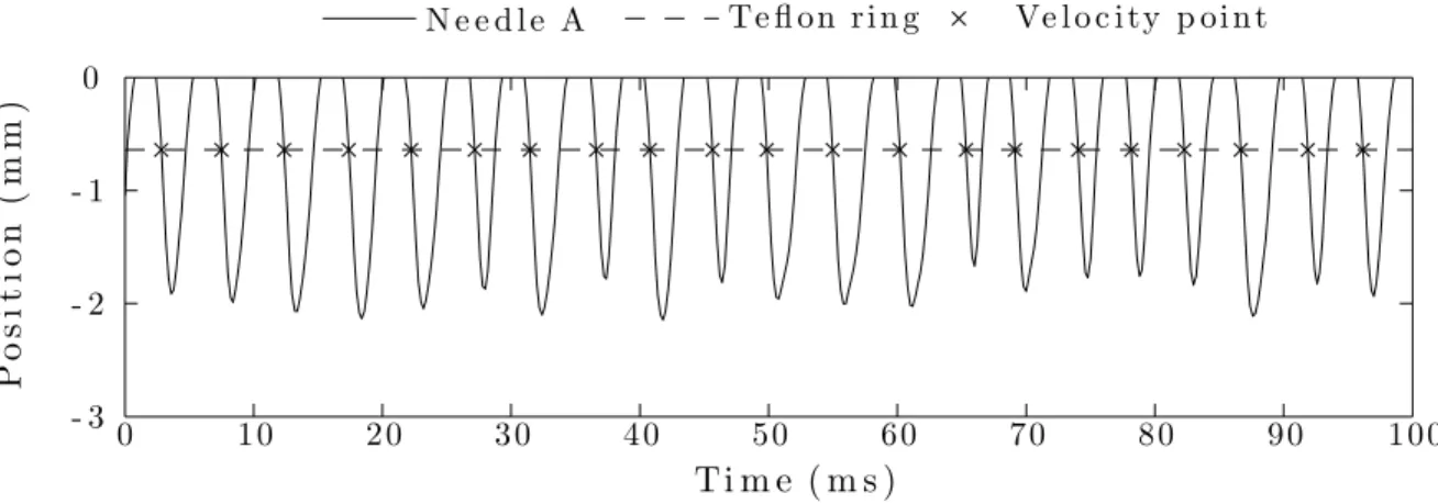
Figure 4.3 Comparison of regression fit smoothening functions . . . 26
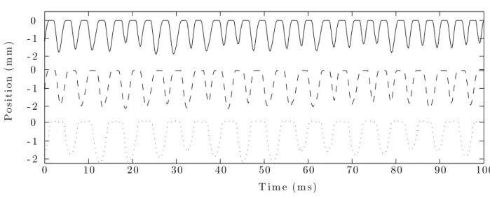
Figure 4.4 Typical needle tip position as a function of time and computation of velocity at impact location . . . 26
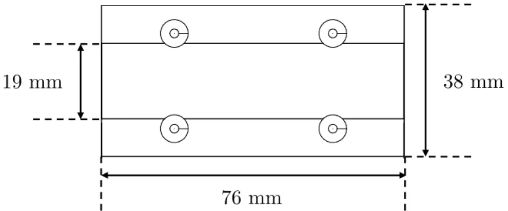
Figure 4.5 Test sample attached to an Almen holder and dimensions . . . 28
Figure 4.6 Three-dimensional FE model . . . 30
Figure 4.7 Unpeened areas in test specimen after needle peening . . . 32
Figure 5.1 Individual needle velocities as a function of air pressure . . . 33
Figure 5.2 Comparison between the dynamics of needles A and B; p = 68.95 kPa (10 psi) . . . 34
Figure 5.3 Needle tip dynamics progression as a function of air pressure . . . 34
Figure 5.4 Individual needle impact frequencies by air pressure . . . 35
Figure 5.5 Saturation curve for p = 137.89 kPa (20 psi) . . . . 36
Figure 5.6 Saturation curves for p = {68.95, 103.42, 137.89, 172.37, 206.84} kPa ({10, 15, 20, 25, 30} psi) using Almen gauge values . . . . 37
Figure 5.7 Measuring path and CMM fixture diagram of test specimens . . . 38
Figure 5.8 Specimen deflection profiles measured by CMM for p = 137.89 kPa (20 psi) . . . 38
Figure 5.9 Arc height and saturation curve comparison between the deflection measurements using the Almen gauge and the CMM . . . 39
Figure 5.10 Saturation curves for p = {68.95, 103.42, 137.89, 172.37, 206.84} kPa ({10, 15, 20, 25, 30} psi) using CMM values . . . . 40
Figure 5.11 Microscopic photography of indentations of test sample peened at p = 137.89 kPa (20 psi) . . . . 41 Figure 5.12 Sampled indentation diameters and average size for p = {68.95, 103.42,
137.89, 172.37, 206.84} kPa ({10, 15, 20, 25, 30} psi) . . . 42 Figure 5.13 Residual stresses σres profile on an AA2024-T3 strip peened at p =
137.89 kPa (20 psi) . . . . 43 Figure 5.14 Convergence analysis between Rn/10 (Gariépy et al., 2011) and Rn/15 44 Figure 5.15 Surface nodes UZ after single impact for v = 1.57 mm/ms . . . . 45 Figure 5.16 Stresses in the X -direction measured under the impact point for v =
1.57 mm/ms after a single impact . . . . 46 Figure 5.17 Cross-section induced stresses contour plot after single impact at
vari-ous impact velocities . . . 46 Figure 5.18 Average induced stress: N = {10, 20, 40, 80, 160, 320}, v = 1.57 mm/ms 48 Figure 5.19 Simulation calculation time: N = {10, 20, 40, 80, 160, 320}, v = 1.57
mm/ms . . . 49 Figure 5.20 Simulated arc heights and fitted saturation curve for v = 1.57 mm/ms 49 Figure 5.21 Residual stress balancing for saturation of v = 1.57 mm/ms and
com-parison with experimental results . . . 50 Figure 5.22 Cross-section, internal state of the material at saturation for v = 1.57
LIST OF ACRONYMS
ANN Artificial Neural Network CMM Coordinate Measuring Machine DRX Diffraction Rayons-X
DSLR Digital Single-lens Reflex FE Finite Element
FOD Foreign Object Damage
LOWESS Locally Weighted Scatterplot Smoothing MÉF Modèle des Éléments Finis
MMT Machine à Mesurer Tridimensionnelle RP Reference Point
SAE Society of Automotive Engineers XRD X-ray Diffraction
LIST OF SYMBOLS
αR Mass-proportional dampping coefficient βR Stiffness-proportional damping coefficient µ Friction coefficient
νn Needle’s Poisson ratio νt Target’s Poisson ratio ρn Needle’s density ρt Target’s density σaxial Axial stress
σbend Bending stress
σind Induces stress
σcmax Maximum compressive stress σres Residual stress
σsurf Surface residual stress
σ0 Target’s initial yield strength
σx Residual stress in x σt
max Maximum tensile residual stress
ah Arc height
Alp Largest indentation area meeasured for pressure p Asp Smallest indentation area meeasured for pressure p
AhAlmenSat Arc height at saturation using the Almen gauge measurements Ahcmm
Sat Arc height at saturation using the CMM measurements
AhpSat Predicted arc height at saturation Ah(t) Arc height as a function of time
b Width
C% Coverage percentage CI Confidence interval Dind Indentation diameter
dlp Largest indentation diameter meeasured for pressure p dsp Smallest indentation diameter meeasured for pressure p DS Scaling factor
En Needle’s Young modulus Et Target’s Young modulus
fi,p Impact frequency of needle i for pressure p Fx Compressive force in X-axis
h Thickness
H Target’s strain hardening coefficient I Width of the impact region of the target It Moment of inertia
l Length
Lbw Color threshold parameter
Lki Coordinate of impact k in the i axis Mi,j Matrix of dimensions i × j
mn Needle’s mass
Mx Bending moment in X-axis N Number of impacts
NSatp Predicted number of impacts at saturation p Air pressure
rstylus CMM stylus tip radius
Rn Needle’s tip radius R2 Regression coefficient
si,p Position of needle i at pressure p
t Time
TAlmen
Sat Saturation time using the Almen gauge measurements
Tcmm
Sat Saturation time using the CMM measurements
Tp Saturation time at pressure p Ui Node displacement in the i axis vi,p Velocity of needle i at pressure p Vn Needle’s volume
z Depth
zmax Maximum residual stress depth
CHAPITRE 1 INTRODUCTION
1.1 Introduction to needle peening
Peening consists of repeatedly striking the surface of a part with a hard object in order to induce near surface plastic deformation. Numerous types of peening processes use different means of creating the impacts, such as shot peening, flapper peening or needle peening. It is through this plastic deformation that peening induces surface compressive residual stresses that have been found to increase fatigue life. Peening is widely used in the aerospace industry to improve the fatigue life of metallic components. It is equally used as a metal forming process for thin components such as wing skins or to correct distortion due to manufacturing. Portable peening technologies, such as flapper peening, were invented in the 1960’s for US army helicopter on-site damage repairs during the Vietnam war, and are increasingly used in contemporary industrial applications.
Needle peening uses relatively hard spikes, called needles, powered by a pneumatic source in order to hit the surface of a ductile workpiece. As the powered tool is pressed against and moved along the component’s surface, the impacting needles stretch the impacted surface, creating indentations as seen in Figure 1.1(a). The bulk of the substrate surrounding the deformed material opposes this stretching, therefore creating a region of compressive stresses, as seen in Figure 1.1(b). The near-surface compressive layer of the deformed material hinders crack propagation under cyclic loading and therefore increases the material’s fatigue life. Needle peening results in a clean procedure that does not require media collection systems.
SPIKER TM Target
Indentation ⇥15
Trajectory
(a) Creation of indentations due to needle impacts
(b) Development of a compression area as a response to the indentation (Mayuram, 2013)
This process is suitable for manufacturing environments where Foreign Object Damage (FOD) and personnel health and safety would be compromised by using a non-captive peening technology. The absence of consumable material also makes it optimal for local repairs and constitutes therefore a highly practical portable repair equipment. In overall, needle peening has a high adoption potential because of its portable design and operation features that target niche overhaul needs currently not covered by current peening equipment.
Peening parameters such as the media material properties, size, geometry, impact velocity and target material properties have an influence on the peening results. Coverage refers to the percentage of the total surface that has been impacted. Peening intensity measures the total energy transferred from the media to the material as a function of the material deformation that results from the peening induced relaxation. Standardized test strips are treated with peening equipment for different process parameters and times, and their coverage and peening intensity are measured. The measurements and inspections done to these strips are then used to determine the quality of the peening process. A thorough understanding of the relationship between process parameters and their effect on the peening results is key to ensure the correct application of this process. The Literature Review in Chapter 2 provides more details about the peening effects.
1.2 Problem definition
Shockform Aeronautique Inc. is a Quebec based pioneer in peening equipment solutions for repairs of high-value components in the aerospace and defense industries. Shockform is currently developing a portable needle peening tool called the SPIKER for peen formingR
and local repairs. The SPIKER is currently in the prototyping phase and studies showR
promising results. The goal is to establish needle peening as a viable alternative to manual shot peening and rotary flapper peening for niche applications.
Numerical tools have been used in the past to predict the effects of conventional shot peening. Such tools could be used to better understand the effect of the process parameters such as needle size, shape and the applied pressure on the induced forming effects in the case of nee-dle peening. These models would provide Shockform with sufficient knowledge to optimize its design to better meet the requirements of their costumers.
1.3 Thesis overview
The objective of this study was to develop and validate numerical models for predicting the effects of needle peening, such as residual stresses and deflection of thin strips, performed with equipment currently in development. The effects of the driving process parameter (pressure) on the peening parameters (impact speed and frequency) were studied. A dynamic finite element model was developed, based on existing modelling strategies implemented for shot peening, for predicting the development of residual stresses on peened strandardized strips. A forming finite element model was used to predict the deformation of the specimens based on the residual stresses calculated by the dynamic model. The models’ predictions were validated by an experimental campaign that makes use of the prototype developed by Shock-form.
CHAPITRE 2 LITERATURE REVIEW
2.1 Introduction to peening
Surface treatment is used particularly in the aerospace industry to improve the fatigue life of metallic components. During peening, a workpiece is cold worked repeatedly using a hard body to plastically stretch the surface to improve its fatigue properties (Shen and Alturi, 2006). Ancient civilizations have long known that work hardening leads to harder and more durable materials. Military equipment like shields, breast plates, spear heads and swords were harder and stronger because of blacksmith hammering (Hawkinson, 1962). The evolution of peening techniques has led to the development of specialized and larger-scale technologies such as shot peening, ultrasonic peening, rotary peening and needle peening.
A component impacted with a small projectile undergoes local tensile plastic deformation. A compressive residual stress field is developed in the near-surface layer as a consequence to the continuity conditions between the elastic and the plastic deformation zones. This means that the bulk of the material opposes the plastic deformation of the indentation by a manifestation of compressive stresses in the near surface. The compressive stress field hinders crack nucleation and growth of very short surface cracks thus extending the fatigue life of peened components. A typical residual stress field produced after peening is shown in Figure 2.1 where negative residual stresses represent compressive stresses whereas positive residual stresses represent tensile stresses. This stress distribution is characterized by the value of compressive stresses at the surface σsurf, the maximum compressive stresses near the surface
σc
max and the depth at which the maximum is located zmax, the depth of the compressive
residual stresses zc, and the maximum tensile stresses found at the core of the material σmaxt
(Gurova et al., 2012).
2.2 Types of portable peening technologies
2.2.1 Shot peening
The most notable difference between the various types of peening is the media employed to deliver the impacts and the mechanisms by which the media is controlled. Shot peening utilizes airborne media, called shots, made from hard materials such as ceramic or hardened stainless steel. Shot peening is popular for aerospace applications ranging from manual to
( ) (+) zc Residual Stress De pth zmax surf c max t max
Figure 2.1 Typical induced stress profile after peening (Al-Obaid, 1990)
fully automated operations. Shot peening using nozzles is depicted in Figure 2.2(a) where shots are being targeted onto a work piece by means of pressurized air. The size of the shots can vary between 0.18 mm and 2.00 mm in diameter, and can travel at velocities between 40 and 70 m/s (Meguid et al., 1999). Media can also be projected onto a target by radially accelerating media using centrifugal high speed paddled wheels (Tekeli, 2002).
2.2.2 Rotary flap peening
Rotary flap peening was first developed by 3M for helicopters in the 1960’s and it was mainly used to repair small areas by blending scratches or to repair surface damage. The setup consists of small tungsten carbide beads attached to flexible flaps that rotate around a shaft in order to impart impacts to the surface. An illustration of a typical rotary flap peening tool is shown in Figure 2.2(b). A concern revolving about flapper peening is the lack of control of the rotational speed when connected to a non-regulated source of compressed air, which
(a) Shot peening (b) Flapper peening (c) Needle peening
could result in variation in peening results. Progress has been made in this field to develop more accurate controllers that would allow for a more repeatable process (Forgues et al., 2011).
2.2.3 Needle peening
Needle peening consists of a captive media method in which a gun is equipped with needles in a given arrangement. A four-needle arrangement is shown in Figure 2.2(c). When the gun is triggered, the needles are thrown against the surface, powered either pneumatically or by the vibratory effect of a sonotrode. Typical needle peening tools operate at a relatively low frequency ranging from 50 to 100 Hz, while ultrasonic impact treatment tools work up to 27 kHz (Haagensen, 1998). Needle peening is generally applied to welded areas in order to add beneficial compressive stresses to ensure the weld’s life extension. Needle peening is currently used on sub-critical components given the limited experience and research on this process.
2.3 Mechanics of peening
Wohlfahrt (1984) described two different processes of localized plastic deformation that lead to a distribution of compressive stresses at the surface of the material and throughout its thickness (Figure 2.3). The first process stems from the change in the surface topography and work hardening that result from numerous and repeated impacts on the surface. The elastic-plastic stretching of the surface layer results in a maximum compressive residual stress at the surface, as seen in Figure 2.3(a), in the absence of other deformation mechanisms. The magnitude of surface residual stresses is related to the degree of plastic deformation of the surface layers. Figure 2.3(b) shows the stress field stemming from the Hertzian pressure imparted by a statically applied force F . The resulting compressive stress has a maximum value below the surface. The degree of plastic deformation underneath the point of pressure determines the maximum magnitude of the residual stress. The stress profile after shot peening combines features of the two processes.
2.4 Process monitoring
2.4.1 Almen intensity
Peening intensity is the quantity used to determine the effects of shot peening. When a relatively thin piece of metal is peened from one side, it curves in the direction of the incoming
( ) (+) res
(a) Stretching the material sur-face as a result of multiple im-pacts
( ) (+)
F
res
(b) Static pressure indentation as a result of the vertical force F
Figure 2.3 Development of residual stresses as a consequence of (a) surface layer stretching and (b) Hertzian pressure. (Wohlfahrt, 1984)
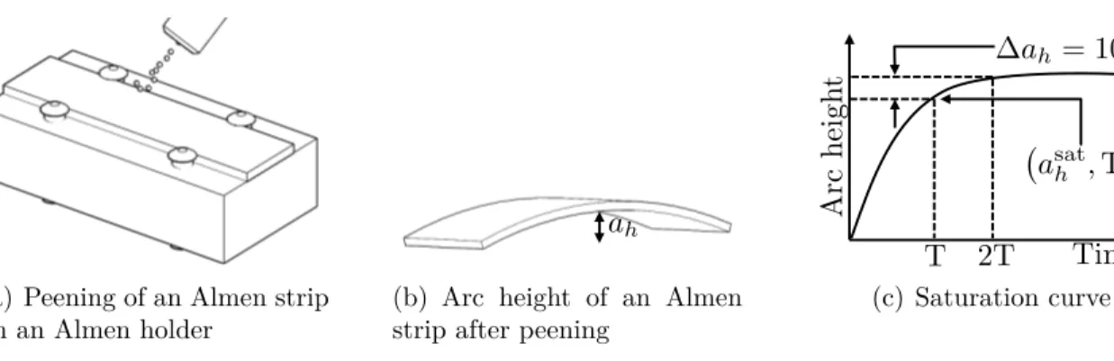
shot flow as a response to the plastic deformation induced by the impacts. Almen intensity is the measurement of the arc height deflection of a test sample; the greater the curvature, the larger is the energy transferred to the work piece. Almen and Black (1963) developed a standard process to measure the energy transfer from a shot stream into standardized samples called Almen strips. The Almen strips are made of 1070 steel and have a length l = 76 mm and a width b = 19 mm. Almen strips come in three thicknesses h: for type N, h = 0.79 mm; for type "A", h = 1.29 mm; and for type "C", h = 2.39 mm (SAE, 2013b). The stages of the process by which the intensity is determined are shown in Figure 2.4. An Almen strip is bolted onto an Almen holder in order to hold the test specimen in position throughout the operation (Figure 2.4(a)). The curvature of the test strip is measured using a three-point contact gauge once the constraints are removed to determine the arc height ah (Figure 2.4(b)). A saturation curve (Figure 2.4(c)) is obtained by peening Almen strips for different treatment times and plotting the measured arc height against peening time. The curve is characterized by the saturation point (asat
h , T ), where asath is the arc height of an Almen strip measured at the earliest instance when doubling the exposure time increases the arc height by a maximum of 10% (SAE, 2010). The peening intensity is the value of asat h commonly measured in thousands of an inch. Depending on the type of Almen strip used, the notation for intensity uses type as a unit signifying thousands of an inch (e.g. if the arc height at saturation on a type A strip is of .008 in., the intensity would be noted as 8A). SAE J442 (SAE, 2013b) and SAE J443 establish the requirements of the equipment and provide guidelines for determining the peening intensity.
2.4.2 Surface coverage
Coverage is a quantity used to monitor the progression of peening on a part. The effectiveness of shot peening is believed to depend directly on coverage; incomplete or excessive coverage may be detrimental to fatigue life. Coverage is referred to as the ratio, expressed as a percentage, between the surface covered by indentations and the total surface area of the target such as:
C% = Areaindented Areatotal
(2.1) In a production environment, coverage is determined through visual inspection using 10X magnification. It is said that a surface has reached full coverage once C% = 98% due to the examination method’s limitations. Coverage beyond full coverage is determined by multiples of the time required to achieve full coverage; for example, 200% coverage is achieved by peening for twice the full coverage time. The standard practices for measuring peening coverage are detailed in SAE J2277 (SAE, 2013a).
2.5 Experimental studies on peening
2.5.1 Shot flow characterization
A study to determine the shot distribution in shot peening was performed by Gariépy et al. (2011) in order to characterize the shot stream and define input model parameters for FE simulations. A peening enclosure was modified to accommodate a Digital Single-lens Reflex (DSLR) camera with a macro lens and a flash to simulate high-speed photography. The photography parameters used were 1/200 s at f 5.6, ISO 200 and flash at 1/28 power with a duration of 1/38500 s. Velocity of the shots was not studied as it could be controlled as a process parameter.
(a) Peening of an Almen strip on an Almen holder
ah
(b) Arc height of an Almen strip after peening
Ar c h ei gh t ah = 10% T 2T Time asath , T (c) Saturation curve
Hribernik and Bombek (2006) developed a method to calculate the shot velocity by means of measuring the phase shift between the signals produced when shots impact a membrane over a microphone. A different approach relies on measuring the phase shift of laser waves projected perpendicularly to the shot stream allowing to calculate the average shot velocity provided the shot flow characteristics are known (Konitzer and Polanetzki, 2011). This methodology has been adopted as a continuous process control method by engine manufacturers (Badreddine, 2014).
2.5.2 Residual stress
Residual stresses are defined as the remaining stresses after manufacture and handling once the material is free of external constraints. Residual stresses develop during most manu-facturing processes involving material deformation, machining or heat treatment (Sharpe, 2008).
Kobayashi et al. (1998) concluded experimentally that the residual stress field and the in-dentation shape due to static contact between a shot and a metallic target are different from those obtained by a dynamic impact of a sphere dropped from a height of 2 m. Tensile resid-ual stresses are created at the center of the indentation by a dynamic impact while they are close to zero for the case of static compression. The shape of the indentations was measured with a roughness meter and the distribution of residual stresses was obtained using the X-Ray Diffraction (XRD) method. Karatas et al. (2009) applied different variations of shot peening parameters and measured the residual stresses induced in type C-1020 steel specimens using the electrochemical layer removal technique. The results were used to train an Artificial Neu-ral Network (ANN) to determine the residual stresses as an analytical expression at different peening intensities.
Kirk (1996) measured surface residual stresses using XRD for needle peened annealed mild steel strip specimens. The effect of peening time as well as the effect of needle geometry was studied. A flat-ended, 2 mm diameter needle and a point-ended 3 mm diameter were considered. Average residual stress values were higher for the flat-ended configuration. The observed average surface stress for the needle peened samples when compared to shot peened samples was smaller. It was concluded that the indentation size was larger for the point-ended needles. Kudryavtsev et al. (2004) measured the residual stresses induced by needle peening in AISI304 stainless steel welded components using the ultrasonic method, XRD, and the neutron diffraction method. The induced compressive stresses depth correlated with the depth of plastic deformation determined by microhardness measurements. Forgues and Polanetzki (2014) compared the induced stress profiles produced by needle peening and shot
σre s (M P a ) D ep t h ( m m ) 0 0. 1 0. 2 0. 3 0. 4 0 . 5 0. 6 0. 7 0. 8 - 1200 - 1000 - 800 - 600 - 400 - 200 0 200 N e e d l e p e e n i n g S h ot p e e n i n g
Figure 2.5 Induced stresses by needle peening and shot peening in Ti6246 (Forgues and Polanetzki, 2014)
peening on titanium alloy Ti6246 at a peening intensity of 0.10 mm A using the hole drilling method. The resulting stress profiles are shown in Figure 2.5. The figure shows that the maximum compressive stress is greater for the case of needle peening. The needle tip radius is equivalent to the shot size used, which was S330 according to SAE AMS 2430.
2.5.3 Material deformation
Wang et al. (2006) measured experimentally the arc-height of unconstrained samples in order to evaluate the response of specimens free to bend and elongate while being shot peened at pressures between 137.89 and 275.80 kPa (20 and 40 psi). The specimens were held to the surface using an adhesive film to prevent lateral displacement during peening. Cao et al. (1995) measured the deformation of constrained and free test strips after 2, 12, 48 and 80 passes of a defined shot peening stream using a surface profilometer along the longitudinal and transverse directions. It was observed in both cases that the degree of deflection increases with a greater number of passes and it stabilizes for large numbers. It was also noted that the arc height is considerably higher in the longitudinal direction than in the transverse. Gariépy et al. (2011) studied the evolution of constrained deflection and the effect of rolling direction in AA2024-T3 test samples with the same dimensions as Almen strips when attached to an Almen holder. Two sets of specimens were cut with the long axis perpendicular and parallel to the rolling direction, respectively. Small differences in arc height were observed between the sets of specimens.
Kirk (1996) measured the curvatures obtained from needle peening mild steel. Substantial curvatures were obtained for 3 mm and 6 mm thick samples. The shapes of the curves
were similar for both material thicknesses, and increasing the tool air pressure lead to faster forming rates. The relationship observed was that the curvature is inversely proportional to the square of the strip’s thickness. The curvature increase with time was found to be similar to that observed in shot peening.
2.6 Analytical studies of peening results
2.6.1 Residual stresses
Li et al. (1991) studied the effect of a single impact on the residual stress state based on the fundamental approaches of Hertz which assumed linearly elastic or ideal elasto-plastic deformation. Research performed by Cao et al. (1995) delivered residual stress distribution using an analytical approach based on the shot diameters and the resulting Almen intensity. Fathallah et al. (1996) built upon this model to add the effects of friction, angle of impinge-ment and hardness ratio between the shot and the target materials. Wang et al. (1998) obtained expressions for the compressive residual stress at the surface, the average peening dent diameter and the depth of the compressive stress field as a function of yield strength, ultimate tensile strength and peening intensity.
Unbalanced induced stresses by peening provoke stretching and bending to reach a balanced state; these manifest as arching of the Almen strips. As a consequence, an overall compressive force Fx and a bending moment Mx must be applied to the strip by the Almen holder to maintain it in a flat shape during peening (Guagliano, 2001). In Figure 2.6(a) the component remains flat after the induction of stresses σindas a consequence of the compressive forces Fx and the bending moment Mx of the form:
Fx = − Z h 0 σinddz Mx = − Z h 0 σind h 2 − z ! dz (2.2)
where h is the material’s thickness and z increases through the material’s depth.
Figure 2.6(b) shows that axial σaxial and bending σbend stresses develop as the constraints
are removed; the residual stresses remain as a result. The relationship between the induced stresses and the residual stresses is given by:
σind+ σaxial+ σbend = σres (2.3)
Fx Fx
Mx Mx
ind
(a) Component maintained flat
ind+ axial + bend = res
(b) Component free to deform upon constraints removal
Figure 2.6 Schematic of the principle of stress forming (Miao et al., 2011)
represents the axial stress originating from material stretching, σbend the bending stresses
and σres the residual stresses. This equation assumes that no reverse yielding occurs. In the
case of thick materials the approximation σind≈ σresis valid since the stretching and bending
deformations are negligible.
It is possible then to calculate the residual stress σres as a function of σind through:
σres= σind+ σaxial+ σbend
= σind+ Fx h + Mx(h2 − z) It = σind− 1 h Z h 0 σinddz − (h 2 − z) It Z h 0 σind h 2 − z ! dz (2.4)
where It is the moment of inertia the target component (Al-Hassani, 1999). For isotropic materials, the same equations are valid for the Y direction.
2.6.2 Material deformation and coverage
Miao et al. (2009) showed from an FE simulation that the influence of stretching on the arc height is negligible. Therefore, the arc height along the length can be approximated as:
AHs ≈ 3Mxl
2
2Ebh3 (2.5)
where l is the strip’s length, E is the Young’s Modulus, b is the strip’s width, and h its thickness. This expression shows that thinner and softer materials will experiment higher deformation under the same induced bending moment.
Guagliano et al. (1999) related the peening parameters to the maximum compressive residual stress using a non-dimensional quantity expressed as a function of the shot velocity, the
shot density as well as the target’s ultimate tensile strength. The relationship allowed for calculating the needed Almen intensity and shot type required for a desired residual stress state. Furthermore, a correlation between Almen intensity and the shot velocity for a given shot type was established and validated through FE simulations and with experimental results (Guagliano, 2001).
Miao et al. (2011) related shot peening intensity and surface coverage to the number of shots impacts. With these equations, the arc height, coverage and surface roughness values at saturation were calculated independently. They concluded that for Almen and aluminum test strips, the relationship between intensities and particle velocities is almost linear. Miao et al. (2010) used the Avrami equation to predict the relationship between coverage and peening time after evaluating the topography of peened AA-2024 to determine the indentation diameters. The influence of shot velocity and peening time on residual stress and surface coverage were validated experimentally.
2.7 Numerical simulations of peening effects using the FE method
2.7.1 Dynamic impact models
The first FE models reported were for single shots hitting an axisymmetric target (Voyiadjis and Kattan, 1983). The verification of the models was achieved by comparing the contact pressure with Hertz’s solution to the contact problem between two spheres; one having an infinite radius which approximated it to a half-space. For the case where plastic deforma-tion was evidenced, verificadeforma-tion was done by comparing the simuladeforma-tion results with surface topology and surface residual stresses from experiments.
The fact that current measuring techniques provide residual stress profiles averaged over a treated area makes the direct comparison of the profile along the axis of symmetry models with experimental depth measurements questionable (Schulze et al., 2008). Other limitations, such as the lack of an accurate representation of multiple and inclined impacts, have lead to the development and application of 3D dynamic FE models (Guagliano et al. (1999), Al-Hassani (1999), Meguid et al. (1999) Guagliano (2001), Zimmermann et al. (2008)). The dynamic analysis performed by Levers and Prior (1998) was used to study the induced stress profile from shot peening. Schiffner and Droste (1999) simulated the residual stress profile in an elastic-plastic surface impacted perpendicularly using different peening parameters. Gratsy and Andrew (1996) showed that a certain amount of deflection occurs between impacts in multi-shot models for thin cross-sections. Zimmermann et al. (2008) simulated the material to tolerate deflection during peening in order to take into account the material thickness into
the development of residual stresses. They demonstrated that the model achieves more realistic predictions of in-depth compressive stresses when compared to experimental results. Miao et al. (2009), Miao et al. (2010) and Gariépy et al. (2011) successfully predicted the induced stresses in AA2024-T3 and AA2024-T351 by implementing a free-face model by constraining all displacements on the bottom surface.
Parametric studies
Majzoobi et al. (2005) researched the effects of shot peening velocity on residual stresses and the development of coverage with a periodic symmetry cell with a square contact surface for high-strength steel 4340. Hong et al. (2008) performed a parametric study to relate shot diameter, velocity and angle to the induced residual stresses using a semi-cylindrical three-dimensional single impact model. In their study Miao et al. (2009) studied the effect of impact angle with constant velocity. Miao et al. (2010) studied the effects of velocity on saturation, surface roughness, coverage and residual stresses for thin and thick AA2024 samples using a tetrahedral three dimensional model.
Effect of meshing
Since a small part of the target is subject to plastic strains, only the region close to the impact area needs to be densely refined (Hong et al., 2008). Figure 2.7(a) shows that a coarser mesh is used in the core of the material in order to reduce the number of elements in the model. Meo and Vignjevic (2003) only studied the impact area and introduced non-reflective boundary bottom elements to simulate the presence of the remaining of the part, as seen in Figure 2.7(b).
Symmetry boundary conditions were applied on the lateral ends of the models by Meguid et al. (1999) allowing the simulation of multiple impacts with a smaller model; this resulted in the mesh seen in Figure 2.8(a). Zimmermann et al. (2008) concluded that this type of symmetric boundary conditions lead to an underestimation of the in-depth residual stresses for relatively thin parts. Miao et al. (2009) divided the study area into four regions, as seen in Figure 2.9. A similar structure was used by Gariépy et al. (2011) showing consistent results while using the mesh parameters studied by Hong et al. (2008). Additionally, the effect of the symmetry boundary conditions on the area covered by indentations was studied.
Hourglassing was visually identified by Baragetti (2001) who noted zigzag shaped elements after the loading portion of the simulation was finished. Hourglass modes are found in under-integrated elements and represent non-physical, zero-energy modes of deformation. This
(a) 2D meshing of the contact model by Zion and Johnson (2006) showing a gradiently re-fined mesh that extends beyond the contact area.
(b) 2D meshing of the contact model of Meo and Vignjevic (2003) limited to the contact area
Figure 2.7 Meshing examples for two-dimensional models
phenomenon can be solved by selecting fully integrated elements or by refining the mesh around the contact zone. Convergence studies to determine the appropriate mesh size were performed by Meguid et al. (1999), Gariépy et al. (2011) and Zimmermann et al. (2008) and the optimal mesh size is selected to be a fraction of either the shot or indentation diameter.
Effect of media distribution
Multiple impact models with predefined impact patterns were studied (Gratsy and Andrew (1996); Han et al. (2002)). Miao et al. (2009) introduced a model in which the impact location was generated randomly within given boundaries. Gariépy et al. (2011) followed a similar
(a) Axial symmetry model by Meguid et al. (1999)
(b) Half-space, single shot model by Hong et al. (2008)
(c) Symmetry cell model by Bhuvaraghan et al. (2010)
Region 1 Region 2
Region 3 Region 4
Figure 2.9 Representative surface modeling proposed by Miao et al. (2009). Region 1: alu-minum surface. Region 2: fine element region. Region 3: boundary of shot centers. Region 4: representative surface.
approach and determined the impact locations by:
Lki = randint(−1000, 1000)
1000 ×
I
2 (2.6)
where Lk
i is the coordinate of impact k in the i = {X, Y } axis, randint(−1000, 1000) is a function that delivers a random integer between −1000 and 1000 following a normal dis-tribution, and I is the boundaries’ width. Both studies ignored the interaction between shots.
Bhuvaraghan et al. (2010) combined the FE model meshed as seen in Figure 2.8(c) with a discrete element model to account for the interaction between particles in the shot flow. Meguid et al. (1999) studied the effect of simultaneous impacts, and concluded that their effect on the resulting stress fields depends on their separation distance. Schwarzer et al. (2002) and ElTobgy and Elbestawi (2004) used three-dimensional models to study the simul-taneity and close succession of impacts on the peening results. The study carried by Gariépy et al. (2011) concluded that simultaneous impacts were separated enough to ignore this effect in simulations. Zimmermann et al. (2010) determined that while the deterministic and the randomly generated impact models provided a good approximation of shot peening results in terms of residual stresses, the latter resulted in a more accurate prediction because of the more realistic assessment of surface topography.
Effect of shot deformation
Many studies including that of Han et al. (2002) assumed shots as rigid bodies to reduce calculation time. This assumption is no longer valid when dealing with harder materials for which the yield strength of the target and shot are in the same order (Schulze et al., 2008). Mori et al. (1994), Rouhaud and Deslaef (2002), Hirai et al. (2005) and Zion and Johnson (2006) studied the elastic and elasto-plastic deformation of the shot and it was concluded that a yield stress ratio of 2 between the shot and the target does not lead to plastic deformation of the shot. In the case where the media should deform, ignoring this effect may lead to an overestimation of the magnitude and depth of the maximum compressive residual stress.
Stress waves and damping
Stress waves were found to reflect at the model’s boundaries, leading to stress oscillations in dynamic shot peening models with small dimensions. Al-Hassani (1999), Schwarzer et al. (2002), Klemenz et al. (2005), Bhuvaraghan et al. (2010) and Zimmermann et al. (2008) employed infinite elements to avoid the presence of stress waves reflection. Guagliano (2001) agreed that the stress in the plate will oscillate around an average value, which they took to be the stable residual stress. ElTobgy and Elbestawi (2004) and Meguid et al. (1999) applied numerical damping in the form of stiffness and mass proportional damping in ANSYS LS-DYNA. Gariépy et al. (2011) used Rayleigh damping with the stiffness-proportional damp-ing coefficient βR = 0.75 ns and mass-proportional damping αR = 8 × 10⁻⁵ s−1 in ABAQUS. Their selection of damping parameters did not affect notably the impact behaviour and remarked that damping is but a numerical tool and it does not represent actual physical damping properties of the material. Meo and Vignjevic (2003) introduced a non-reflective boundary surface to simulate the presence of additional substrate for thicker components.
Effect of contact friction
Friction was considered as an influencing parameter on the results of peening. Meguid et al. (1999) determined that the presence of friction, in the form of the friction coefficient µ, between shots and the surface leads to a decrease in surface plastic deformation and surface residual stresses. Similar conclusions on the effect of friction were studied by Mori et al. (1994), Han and Peric (2000), Zion and Johnson (2006) showing that friction does not have a significant effect in the variation of residual stresses and plastic strains for 0.1 ≤ µ ≤ 0.5. Miao et al. (2009), Miao et al. (2010) and Gariépy et al. (2011) adopted for µ = 0.2. Bhuvaraghan et al. (2010) opted to ignore the effects of friction.
Thermal effects
Evans (2002) studied thermal effects in stainless steel, titanium and aluminum alloys. They concluded that thermal strains have no significant influence in the development of residual stresses when there is no inter-material thermal conduction and all the induced heat remains in the deformation zone. A combined mechanical/isothermal single impact simulation done by ElTobgy and Elbestawi (2004) confirmed this conclusion. Rouquette et al. (2009) noted high surface temperatures reaching up to 180oC in the impact area. Thermal expansion leads
to a significant reduction in the residual stress amplitude. There could be an overestimation of the temperatures attributed to the fact that the shot was considered rigid, and no energy was lost to its deformation.
2.7.2 Material constitutive theory
Strain-rate sensitivity
Kobayashi et al. (1998) demonstrated experimentally the difference between the static and the dynamic model solutions of a single indentation. Their study concluded that this effect could be attributed to the strain rate sensitivity of the model, which is ignored in the static loading case. Chen et al. (2014) evaluated the effect of rate-dependent behavior of 4340 steel by conducting two FE simulations. They first assumed no strain-rate sensitivity; the second case incorporated strain rates up to 105 s−1. It was noted that the strain rate effects lead to
a reduction in the plastic zone and an increase in the resulting residual stress for the same impact energy. The increase in the amplitude of the residual stress field leads to a larger arc deformation for rate sensitive materials.
Meguid showed numerically that plastic strains up to 6 × 10⁵ s−1 are present during shot
peening. Bhuvaraghan et al. (2010) considered strain-rate dependency into the determination of the elastic-plastic properties of IN718. The properties were obtained using the Johnson-Cook equation. This implies that subsequent impacts will hit a harder surface. Mylonas and Labeas (2011) concluded that for high strain values the deformation rate plays a significant influence on flow stresses affecting the shape of the indentations. The effect of train-rate sensitivity was neglected in more recent studyies by Miao et al. (2009) and Gariépy et al. (2011).
Material hardening laws
The degree of cold work is important in the simulation of shot peening as the work-hardened material may show modified properties when compared to the untreated material as noted by Mylonas and Labeas (2011). Isotropic hardening describes a yield surface that expands equally in all directions on a plane. It implies that an increase in tensile yield strength results in an equal increase in compressive yield. Kinematic hardening describes a constant yield surface that translates in the direction of yielding, otherwise known as the Bauschinger effect. It predicts that an increase in tensile yield strength produces a corresponding decrease in compressive yield strength. Elastic-perfectly-plastic materials exhibit no hardening.
The influence of elastic-perfectly plastic and elasto-plastic material deformation behavior with isotropic strain hardening was studied by Kral et al. (1993) for a single impact. Miao et al. (2009) assumed an isotropic bilinear hardening law for their three-dimensional random peening simulation. Mylonas and Labeas (2011) applied a multi-linear elastic-plastic material model with kinematic hardening for AA7449-T7651. Klemenz et al. (2005) proposed an elasto-viscoplastic material model with combined isotropic-kinematic hardening to describe cyclic deformation. Gariépy et al. (2011) and Rouhaud et al. (2005) showed that using a kinematic hardening model can lead to a significant decrease of compressive residual stresses compared to isotropic hardening due to the reversed plastic flow that occurs during unloading. Gariépy et al. (2011) performed low-cycle, high-strain cyclic mechanical testing of unpeened material in order to develop a material constitutive law for shot peening. The test samples made from AA2024-T351 were tested at a rate of 8 × 10⁻⁵ s−1. Monotonic and cyclic yield stresses were determined with the 0.2% method at different strain amplitudes. Majzoobi et al. (2005) obtained the Johnson-Cook constants from stress-strain curves to consider strain-rate sensitivity for steel plates.
2.7.3 Peen forming
Peen forming is a dieless metal forming technique in which the surface of a component is bombarded by high speed shots that induce a thin layer of plastic deformation near the surface (Miao et al., 2011). These deformations induce an isotropic stress profile that causes the component to curve towards the peening direction. Macro models are commonly developed to simulate peen forming and to predict the component’s curvature based on peening parameters (Schulze et al., 2008). Multiple impact equivalent approaches have been introduced so as to avoid simulating the millions of shots required to peen larger components (Gariépy et al., 2011). The equivalent "squeeze pressure" was introduced to shot peening by Gratsy and
Andrew (1996) in which yielding of the surface elements was forced by the introduction of a squeezing pressure in order to obtain plastic deformation an residual stresses. Levers and Prior (1998) and Zeng (2002) made use of the thermal loading method by creating thermal strains to introduce stress distributions. In these cases, the temperature was only used as a numerical tool and does not represent the increase in temperature involved in the process. Chen et al. (2014) suggested a two-step process approach to simulate the arc height de-velopment. The first step consists of repeated spherical impingement of an Almen strip. Symmetry boundary conditions were used to represent a quarter of a test strip mounted on an Almen holder. The second step consisted of balancing the internal stresses once the part is peened and later removed from its constraints. It was found that the arc height increases with the number of impacts and it reaches an asymptotic value; a behavior observed in the shot peening process while developing saturation curves.
In order to avoid peening a full part Gariépy et al. (2011) proposed a dynamic impact model to simulate the peening in a periodic cell. The forming model would then be used to determine the arc height based on an uniform coverage of what would be an Almen strip-sized component. The following assumptions were made:
a) Normal and uniform peening generates induced stresses at the component scale that only depend on depth, meaning these are uniform in the X − Y plane.
b) The effect of trajectory is neglected when modeling multiple passes.
c) Miao et al. (2009) determined the initial rolling stresses by XRD and concluded that the development of near-surface induced stresses is almost insensitive to the initial rolling stresses.
d) Peening of the surface does not lead to severe plastic deformation at the material’s core. e) Induced surface stresses are those calculated from the dynamic impact model.
CHAPITRE 3 PROJECT RATIONALLE AND OBJECTIVES
The literature review revealed the following:
• The repeated action of impacting the surface of a ductile workpiece induces stresses as a result of the surface stretching. The resistance of the material’s bulk to these plastic deformations leads to the development of compressive residual stresses in the near-surface that improve fatigue properties of the treated target and a layer of tensile stresses develops within the material’s depth. Portable surface treatments techniques, such as shot peening and needle peening, are capable of providing these enhanced material properties.
• Thin samples exhibit an arc-like deflection as a result of stress-rebalancing to reach equilibrium. The deflection magnitude is commonly used to define the peening intensity as a quantity that serves as process control. Experimental campaigns have studied the effect that certain process parameters bear on the results of peening, particularly in the development of residual stresses and the associated material deflection. Knowledge of the material and contact properties of the peening system are therefore required in order to properly develop a robust process. These are obtained either by characterization of the equipment or the material.
• The characterization of AA2024-T3/T51 performed by Gariépy et al. (2011) provides good reference to investigate the effects of different types of peening on the same mate-rial. Similar assumptions to those listed in Chapter 2 can be made regarding the model types and geometry, material sensitivity to strain-rate and hardening. The fact that it is relatively insensitive to high strain rates and that its reaction to shot peening has been extensively studied at the Laboratory of Multiscale Mechanics (LM2) of l’École Polytechnique de Montréal make it an ideal candidate for this study since material characterization is not in the scope of this project.
• Very little is known about the effects of needle peening for the development of induced stresses. No numerical simulation exists in the public literature for simulating the residual stresses and material deflection due to needle peening. An experimental and numerical study is needed in order to better understand the process and pave its intro-duction for potential business applications. The random dynamic FE model developed by Miao et al. (2009) can accurately predict the development of induced stresses by peening AA2024. Similar assumptions regarding contact friction and shot rigidity may
apply to the case of needle peening. The model dimensions studied by Gariépy et al. (2011) may be used in order to adapt the models to the geometrical and operational parameters of needle peening.
The questions raised during the literature review are:
1. Can the existing assumptions and conclusions derived from the research of shot peening be tailored to model needle peening based on the equipment’s process parameters? 2. Assuming the target material properties from previous studies and a random
distribu-tion of impacts, can the newly developed models accurately predict the effects of needle peening (induced stresses and material deflection) on AA2024-T3 Almen strip-shaped samples?
The answering of these questions have lead to the following objectives:
1. Characterize the operation of needle peening equipment and experimentally study the effects of its application on AA2024-T3.
2. Develop and validate numerical models for predicting the induced stresses and the material deflection as a result of the application of needle peening.
The research project guided under these objectives is presented through the research method-ology (Chapter 4) of the equipment characterization and the simulation strategy of needle peening using the FE method. The results obtained (Chapter 5) from the numerical simu-lations are presented and validated using experimental results. A general discussion of the results (Chapter 6) and a conclusion (Chapter 7) follow.
CHAPITRE 4 RESEARCH METHODOLOGY
4.1 Needle peening application on AA2024 and process characterization
This section describes in procedural form the tasks performed in order to analyze the be-havior of the portable needle peening equipment SPIKERTM. The equipment geometry was
characterized based on the engineering drawings given by the industrial partner. High speed camera recording was used to study the dynamics of the equipment during its application. A digital image processing model was developed to quantify the tool’s operational parameters. The reaction of AA2024 was studied through an experimental campaign. Test specimens were peened using the needle peening equipment. The specimens’ deflection was measured after different treatment configurations. Surface plastic deformations were quantified in terms of the indentation diameters. Finally, the residual stress profile was determined for one of the samples.
4.1.1 Equipment characterization
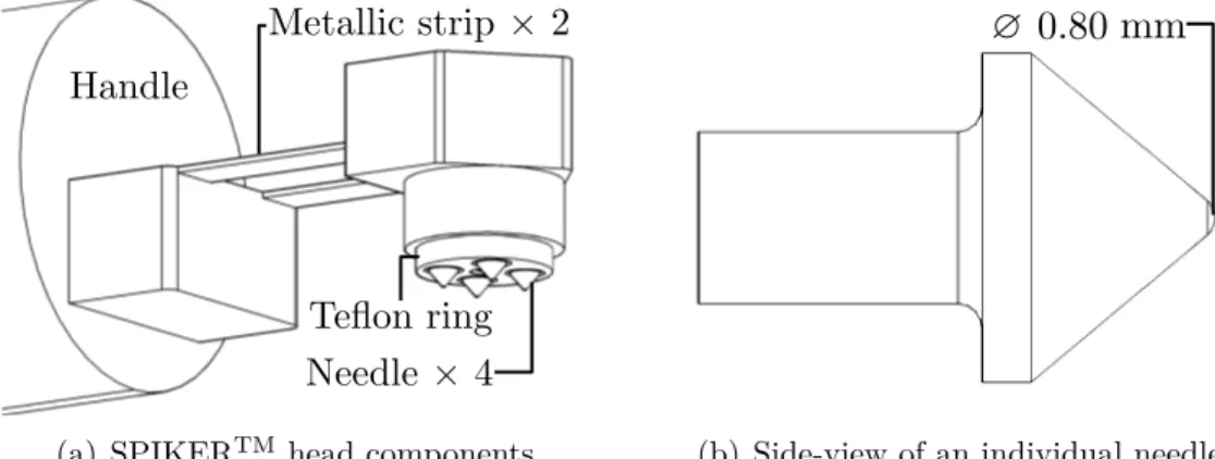
The equipment used for the study is a portable pneumatic needle peening equipment in prototype form. Figure 4.1(a) shows the equipment as well as its key components. The air powered handheld device features four protruding needles traveling along their axes due to the pneumatic pressure and internal mechanisms. The needles’ geometry is shown in Figure 4.1(b); only the needle tip diameter is shown as the other dimensions are confidential. These needles are attached to the pneumatic sleeves connected to pistons. The head is covered by a teflon ring that controls the stand-off distance during peening. The head is attached
Handle
Teflon ring Needle ⇥ 4 Metallic strip ⇥ 2
(a) SPIKERTM head components
? 0.35 mm0.80
(b) Side-view of an individual needle
by a pair of thin metallic sheets that bend in order to ensure that the contact between the equipment and the work piece is continuous.
A 3D model was drafted using AUTOCADTM2015 for Mac, version J.31.M.313 using the
ge-ometrical information provided in the engineering drawings. The volume of the needle Vn was calculated using the VOLUME function. The needles’ density ρn was obtained from the manufacturer and their masses mn were computed as
mn= ρnVn (4.1)
High-speed camera recording
High speed photography was used to analyze the dynamics of the needles during peening under various operation conditions. The tool was held into place by means of two 1 EMT 1308 galvanized steel straps, as seen in Figure 4.2(a). A high-speed recording camera MotionBlitz
R
Cube4 was used with a 60 mm f 2.8 lens perpendicular to the X − Z plane. The tool
head was rotated slightly so as to have the four needles in frame simultaneously. Two 1200 W light sources were positioned behind the camera pointing at the tool to improve lighting conditions for obtaining images of optimal quality. A clear white photography screen was positioned in the background for an improved contrast.
The operation parameters were selected using the tooling’s internal digital controller for air pressure p = 68.95, 103.42, 137.89, 172.37, and 206.84 kPa (10, 15, 20, 25, and 30 psi). The air pressure range exceeds the lower and upper typical operational limits recommended by equipment manufacturer. The frames were recorded individually as .bmp files at a recording frequency of 5000 fps at a resolution of 480 × 206 pp. For each of the operating pressures, the recording lasted 200 ms, meaning that 1000 frames were obtained per pressure. The time
x z
y
(a) Equipment holding fixture for camera recording. D A B C D RP x z (b) Frame subdivision.