Application of the Galileo System for a Better
Synchronization of Electrical Power Systems
Philippe Mack, Florin Capitanescu, Mevludin Glavic, Fabrice Legrand, Louis Wehenkel
Abstract— In this paper we present objectives and strategies of
the NAVELEC research project funded by the European Union Galileo Joint Undertaking (GJU/05/2423). The project objective is to assess how the European Global Navigation Satellite System related solutions can enhance the operation and control of the European power system over wide areas. Some basic functionalities of the GALILEO system are given first, then we summarize the questionnaire, set at the initial stage of the project, and provide the analysis of received responses from transmission system operators. Two generic strategies to upgrade existing electrical power transmission networks with functionalities, as well as major steps to upgrade underlying infrastructures, are discussed in this paper.
Index Terms — Power system monitoring and control,
Synchronized wide-area measurements, Galileo system, Global navigation satellite system.
I. INTRODUCTION
P
OWER transmission networks, together with their communication and control systems, have evolved over several decades utilizing new technologies as they have appeared [1]. This evolution has been slow and incremental and the slowness is attributed to the vertical organization power utilities had until recently. Recent changes, both in policy and technology, as well as several recent system blackouts require a new look into the operation of power networks and their communication and control infrastructures and faster deployment of available technological solutions [1,2,3]. Recent technological advancements in terms of computational facilities, their networking infrastructure, communications, and measurements with time synchronizing capabilities, have created new opportunities for designing wide-area monitoring, protection, and control schemes to help overcome the limitations of existing solutions [4].Indeed, research and study efforts are needed in order to determine feasibility, costs, and benefits of the new solutions. Based on findings of these efforts a possible development toward the real implementation can be adopted.
In this paper we present the NAVELEC research project funded by the European Galileo Joint Undertaking. Its objective is to assess how GALILEO-related solutions can enhance the operation and control of the European power
system over wide areas. GALILEO is the European Global Navigation Satellite System (GNSS), intended to provide a highly accurate, guaranteed global positioning service under civilian control. While providing autonomous navigation and positioning services, GALILEO will be interoperable with the USA Global Positioning System (GPS) and the Russian one (GLONASS).
P. Mack is with PEPITe, SA, Liège, Belgium. F. Capitanescu and L. Wehenkel are with the Electrical Engineering and Computer Science Department, the University of Liège, BELGIUM. M. Glavic is with DELING, doo, BOSNIA. F. Legrand is with M3Systems, Toulouse, FRANCE.
We first present relevant GALILEO functionalities. Then we focus on the questionnaire, set up to identify the relevant needs for improved system wide-area monitoring and control applications [5], and sent out to a number of European Transmission System Operators (TSOs). We provide a summary of the analysis of the responses from TSOs [6]. Finally, we present two generic strategies to upgrade existing electrical power transmission networks with GNSS functionalities, as well as the major steps to upgrade the underlying infrastructures [7]. The proposed strategies, both gradual and based on system-wide replacement, include several steps with the final aim of implementing a full interconnection-wide real-time monitoring, protection, and control system based on time-synchronized measurements.
The NAVELEC project has started in March 2006 and is scheduled to complete in April 2007.
II. NAVELEC APPROACH
A. The consortium and general objective
The NAVELEC consortium is composed of 4 partners: • PEPITe - a Belgian small-medium enterprise (SME)
specialized in industrial data mining applications (most notably in energy, steel glass and paper sectors as well as in the aerospace industry,
• The Systems and Modeling research unit of the University of Liège (Department of EE&CS),
• DELING - a SME from Bosnia and Herzegovina, specialized in power system engineering and consulting, • M3Systems - a French SME specialized in space and
aerospace engineering and consulting.
The general objective of the project is to assess how GALILEO related solutions can provide enhancement of the operation and control of the European interconnected power system over wide areas.
B. The approach
In order to achieve the project general objective the following major activities have been scheduled:
• Identification of the relevant needs for improved system wide-area monitoring and control applications using synchronized measurements in the context of the operation and control of the European interconnection.
• Assessment of how existing electric power networks need to be upgraded in terms of GNSS functionalities for implementing a real-time GNSS-based information infrastructure with high quality, high reliability time-stamped information which would be accessible to TSOs. • Evaluation of the benefits against costs brought by the use
of the GALILEO-related solutions as a synchronization tool for the operation and control of the European Interconnection.
• Evaluation of the GALILEO performances regarding the requirements of end-users (TSOs and EMS vendors)
III. GALILEO: MOTIVATION AND FUNCTIONALITIES
A. Motivation for alternative GNSS
The Synchronized Phasor Measurement Systems (SPMS), also referred more generically to as Wide Area Monitoring System (WAMS), are a relatively new technology that has been already adopted in some countries worldwide (see [4] for a comprehensive survey). To the author's knowledge, all SPMS-based applications use a GNSS system for measurement synchronization. Except of some local alternatives (e.g., GLONASS in Russia, Beidou in China) the single such GNSS widely used, up to now, is the GPS.
The GPS is a free of charge system designed especially for military applications. Nonetheless, many engineering applications actually rely on the GPS signal. Clearly, for many civilian applications worldwide, it is insecure to rely only on a single GNSS, especially a military one. Indeed, being designed as a military application, it is difficult to foresee for how long the GPS signal will still be available (and free of charge) for civilian applications. Furthermore, the GPS can be seen as an important target during war and/or terrorist attack. These were the main reasons that gave rise to the European initiative for having an alternative GNSS, designed as a non-military application, and named GALILEO [8].
B. The GALILEO: short overview and functionalities
The GALILEO comprises a constellation of 30 satellites divided among three circular orbits at an altitude of 23222 km to cover the Earth’s entire surface. Each GALILEO satellite will broadcast 10 different navigation signals, making it possible to offer the open, safety-of-life, commercial, and public regulated services [8.9].
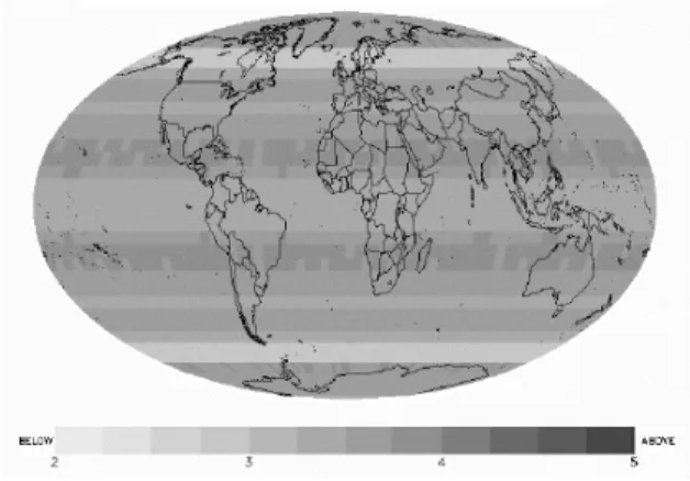
GALILEO will have an integrity signal to ensure the quality of the signals received. The signals will offer a guaranteed accuracy down to 1 meter, with value-added services achieving real-time accuracy of 10 cm [8,9] for positioning applications. The GALILEO’s Earth coverage and accuracy for positioning applications are illustrated in Fig. 1 [8]. The GALILEO time precision in terms of time errors (95% confidence) for different signals is given in Table I.
In addition to the global coverage and high time precision for synchronization, the GALILEO availability is better than 99% with value-added service (for safety related applications) [8,9] and it has been declared as open (interoperable) with other GNSS services.
Fig. 1 Vertical accuracy obtainable with GALILEO MEO (Medium Earth Orbit) constellation (Ranges 2-5 meters)
TABLE I
GALILEO SIGNALS CONTRIBUTION ON THE SYNCHRONIZATION ERROR
Signal L1 E6 E5A E5B E5AB
Time error (95% confidence)
8.1ns 3.6ns 1.8ns 1.8ns 0.7ns
The main advantages of GALILEO over the other GNSS solutions are listed below [9]:
• GALILEO has been designed and developed as a non-military application, while incorporating all the necessary protective security features. Unlike other GNSS, GALILEO provides, for some of the services offered, a very high level of continuity required by modern business, in particular with regard to contractual responsibility; • It is based on the same technology as other GNSS and
provides a higher degree of precision, thanks to the structure of the constellation of satellites and the ground-based control and management systems;
• GALILEO is more reliable as it includes a signal "integrity message" informing the user immediately of any error. In addition, it will be possible to receive GALILEO at places located in extreme latitudes;
• It represents a real public service and, as such, guarantees continuity of service provision for specific applications. Other GNSS signals, on the other hand, in recent years have become unavailable on several occasions on a planned or unplanned basis, sometimes without prior warning.
Note that the GALILEO is designed not only to compete but also to complement the GPS. Thus using these two GNSS signals in a coordinated fashion would yield real improvements in terms of precision and security.
The GALILEO is planned to be fully operational by 2010 (see the European Space Agency website: www.esa.int).
IV. SUMMARY OF THE QUESTIONAIRE
The questionnaire has been set in order to identify relevant needs for improving wide area system monitoring and control applications using Synchronized Phasor Measurements (SPM) in the context of the operation and control of the European interconnected power system. This questionnaire has been sent to most of the European TSOs and is organized in five sets of questions with each set targeting different issues, as follows:
• Current state of implementation. The questions about the presence or absence of Phasor Measurement Units (PMUs) in the electric power system at the national level as well as the power system quantities measured.
• Actual and possible future applications. The questions about the actual SPM based applications: off-line applications, on-line applications, and real-time control. • Limiting factors of actual applications. The questions
intended to reveal the main limiting factors of the actual synchronized phasor measurements applications.
• Improvements of SPMS. The set of questions related to the performance requirements for PMUs and related communication channels.
• Sharing synchronized measurements among TSOs. The questions about actual data exchange procedures and the sharing of SPM among TSOs.
The questionnaire has been set such that efficient responses can be given. The most of the questions are of YES/NO type. More information is required only if absolutely necessary.
V. ANALYSIS OF THE RESPONSES
In this section we present an analysis of the answers to the questionnaire [6]. This analysis is based exclusively on 8 responses, which we have received, from TSOs of countries inside the European interconnection, and the "Nordel" system.
A. Current state of implementation
The power systems are in different stages of SPMS implementation, ranging from power systems where a good experience with such systems has been already acquired to power systems where this technology is insufficiently known.
Presently, PMUs have been deployed (and SPMS implemented) only in 3 power systems (out of 8). For 2 systems the number of PMUs is deemed enough for the time being in order to help TSOs achieving the required operational tasks (in the time frames of: planning, operational planning and real time). As regards the 5 power systems where PMUs are not deployed yet, only inside one system few PMUs are planned to be deployed soon. TSOs of 2 (out of these 5 TSOs) consider not necessary to deploy PMUs and consequently to implement SPMS in the near future. On the other hand, for the other 3 systems where PMUs are not deployed yet (and not planed to be deployed soon) recognize that few PMUs would be helpful. The acquisition rate of the existing PMUs is in the range tens to hundreds of milliseconds and synchronized with the GPS signal. Most PMUs are used to measure system frequency and complex bus voltages (phase angle and
magnitude).
B. Actual and possible future applications
All TSOs from systems where the SPMS are not installed yet suggested that the use of SPM will be helpful for most (off-line, on-line monitoring, on-line visualization and on-line control and emergency control) SPMS applications specified in the questionnaire. We provide below, the uses of SPMS in systems where this technology has been already adopted.
Off-line applications. SPM are mainly used for: software simulation validation, system parameter/model identification (e.g. for loads, lines, etc.), synchronized disturbances record and replay, assessment of the "fast" ancillary services delivering (e.g., frequency and voltage control) by power producers, assessment of distributed generation sites performances (especially their ability to remain connected when experiencing significant voltage/frequency decays). An off-line application of great interest is the analysis of poorly damped inter-area low frequency oscillations that will allow better tuning of power system stabilizers in order to mitigate the problem.
On-line applications. SPM are used in on-line mainly to: monitor disturbance events, monitor power system frequency and its rate of change, monitor transmission line temperature, monitor poorly damped inter area oscillations modes (in range of 0.2 - 1 Hz), monitor the "fast" ancillary services delivered by producers, etc. As a by-product of such applications, various SPM-based on-line visualization schemes have been already implemented in control centers. Some important applications of SPM, currently operable in some systems, concern the creation of "smart" alarms (e.g., to monitor frequency variation, to monitor in real-time line temperature, etc.) and better on-line monitoring of the risk of voltage collapse. We also quote some other SPMS applications, not included in the questionnaire, but revealed by some TSOs: on-line monitoring of system damping, on-on-line monitoring of voltage phase angle difference, on-line thermal monitoring, and state estimation enhancement.
On-line and emergency control. SPMS are not yet used significantly for the time being in on-line and emergency control. This is a topic of important interest in the near future.
C. Limiting factors of actual applications
As expected, the main limiting factor pointed out, when using/implementing GPS-based SPMS applications, is the reliability of the communication network for sending SPMs from PMUs to the phasor data concentrator. Nevertheless only 3 TSOs consider that the system existing communication infrastructure is inadequate for the use/implementation of SPMS and foresee to deploy new communication channels (e.g. fiber optic). The other 5 TSOs revealed that the system existing communication infrastructure is adequate. It was also clearly indicated in the responses that the system of synchronized measurements should be deployed in a complete package including the required communications.
One more concern has been expressed (by 2 TSOs) and is related to the (somewhat) unsatisfactory availability of the
GPS signal. The advent of the GALILEO GNSS is expected to improve the signal reliability. The best solution for having better measurements redundancy and signal reliability is to receive in the future both GALILEO and GPS signals.
Another problem revealed is measurement noise in some substations, which makes more difficult accurate (phasor) measurements. A minor point mentioned is about SPM storage aiming to avoid inappropriate or numerous (similar) recordings when not needed. This implies a deeper analysis of measurements sensitivity to some parameter settings. Some difficulties reported relate to the problem encountered to presently match the recorded SPMs with other data from the other SCADA and monitoring tools. Finally, some TSOs consider that the SPM technology is still expensive and the investment in such technology is difficult to justify for some (very meshed) systems. This aggravates with increasing the size of the power systems, which would require a significant number of PMUs and appropriate communication system.
D. Improvements of SPMS
The return of experience concerning the operation of SPMS is generally positive. The operational and maintenance costs are low. There is a need to increase measurements redundancy and signal reliability by using two independent systems. To this end, pressure on PMU manufacturers must be made in order to allow the reception of two different signals. There is also a need for more elaborate signal processing capabilities to extract easily frequency and detect oscillations in the frequency range of interarea oscillations. Thanks to the SPM the post event analysis can be enhanced leading to a better interoperability among the various wide-area measurement systems operated and maintained by different TSOs. Another significant improvement in power system operation is related to the enhancement of system state estimator by using the (accurate) PMU measurements. In all the responses received the use of the GALILEO signal for SPM, alone or together with the GPS signal, has been regarded positively.
E. Sharing synchronized measurements among TSOs
The current practice within the European interconnection is to exchange among TSOs day-ahead congestion forecast, planned interchanges, etc. A promising fact is that some European countries have already exchanged SPM in real-time. All TSOs that responded to the questionnaire, agreed to exchange SPM in real-time which could help preventing large (trans)national blackouts.
VI. UPGRADE STRATEGIES OF EXISTING TRANSMISSION NETWORKS
A. Generalities
Two approaches to upgrade existing electric power networks with GNSS functionalities have been set:
1. System-wide replacement and upgrade strategy, 2. Gradual (incremental or evolutionary) approach.
In both strategies the aim is to establish the steps and
implement an interconnection-wide real-time monitoring, protection, and control system that could give a near-instantaneous picture of the transmission system’s health and allow to act in closed-loop fashion by triggering appropriate protection or control actions.
The communication infrastructure is of paramount importance for proper functioning of the new system whatever the upgrade strategy is adopted. The communication networks have to be designed for fast, robust and reliable operation [10]. Among the most important factors to consider to achieve these objectives are type and topology of the communication networks, communications protocols, and media used. These factors in turn effect communication system bandwidth, latency in data transmission, reliability, and communication error handling. Currently, electric utilities use a combination of analog and digital communication systems for their operations consisting of power line carrier, radio, microwave, leased phone lines, satellite systems, and fiber optics. Each of these systems has applications where it is the best solution.
Fig. 2 Architecture of a synchronous communication network [10] Several types of communication protocols are used with optical systems. Two of the most common are synchronous optical networks and asynchronous transfer mode. Synchronous optical networks are well established in electrical utilities throughout the world and are available under two similar standards: Sonet is the American system under ANSI T1.105 and Bellcore GR Standards, and Synchronous Digital Hierarchy (SDH) under the International Telecommunications Union standards. Synchronous networks are based on a ring topology (see Fig. 2) [10]. This topology is a bi-directional ring with each node capable of sending data either direction. A typical network, however, may consist of a mix of tree, ring, and mesh topologies rather than strictly rings with only the main backbone being rings [1,2,10].
B. System-wide replacement strategy
System-wide replacement and upgrade strategy, illustrated in Fig. 3 (partly based on the experience presented in [11]), consists in an aggressive replacement strategy of the legacy measurement equipment and communication infrastructure.
It requires the system-wide installation of the measurement devices with GNSS time synchronization capability (PMUs) and complete upgrade of existing Intelligent Electronics Devices (IEDs) with possibility to provide GNSS
time-synchronized measurements. The monitoring, protection, and control applications based on this approach are standalone but exchange some information with existing SCADA/EMS. A separate console could be envisioned to monitor the system instability indices, and issue control commands based on the recommendations. The approach is particularly suitable for power system utilities and interconnections where large percentage of existing measurement, protection, and control equipment is old (near the end of their life cycle) and this is one of main driving factors for adopting this approach. Although the age is not direct driver of poor system reliability, there is an increasing trend of failure and increased maintenance costs of the equipment due to the effect of potentially out of specification parts on the performance of the equipment [11]. In order to support system-wide installations of new equipment new functions should be developed in order to make the best use of new information that could be gathered over large geographical areas.
Fig. 3 System-wide replacement and upgrade strategy (SPS-System Protection Scheme, RAS-Remedial Action Scheme)
For each particular power utility, if decided to adopt this strategy (after a careful benefit-costs analysis justifying the investment), the project should be set and include the following steps that make up the overall strategy:
1. Create goals and a far-reaching roadmap for measurement, protection, and control systems design.
2. Evaluate existing monitoring, protection and control technologies and identify their limitations.
3. Evaluate advanced technology (such as GNSS, PMUs, etc.) available in the time frame of the upgrade project. 4. Identify existence of the devices capable to provide fast
scanning rate of the system dynamics (e.g., IEDs, event recorders, etc.) and those having possibility to provide GNSS time synchronized measurements. These devices, if
exist, do not need to be replaced but just upgraded with GNSS functionalities.
5. Identify if mere replacement of existing measurement, protection, and control devices with the new ones would be satisfactory. If not investigate options for installing new devices at new locations.
6. Foresee and define issues for managing new systems and data gathering features.
7. Identify new (at least critical) functions to be developed in order to make the use of wide-area information gathered. 8. Adopt the approach for implementing the strategy
Implementation approach usually includes a pilot phase, followed by initial and full production phases. The purpose of the pilot phase is to demonstrate the effectiveness of the business processes and technological innovations presented by vendors’ proposals. Subsequent production phases will adapt from experience in the pilot phase and repeat the process across the system over several years.
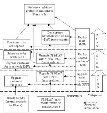
C. Gradual upgrade strategy
In gradual upgrade strategy, graphically illustrated in Fig. 4, one first attempts to establish near-term solution for improved monitoring, protection, and control, based on existing systems and then gradually upgrades the system in order to reach defined final goals [12]. We suggest the following gradual (incremental) approach to the upgrade of existing power transmission networks (organized in two phases):
PHASE 1:
1. Create goals and a far-reaching roadmap for measurement, protection, and control systems design.
2. Evaluate existing monitoring, protection and control technologies and identify their limitations.
3. Identify existence of the devices capable to provide fast scanning rate of the system dynamics (e.g., IEDs, event recorders, etc.) and those having possibility to provide GNSS time synchronized measurements.
4. Identify the possibilities to enhance existing SCADA/EMS as near-term solution.
5. Define data requirements.
6. Upgrade existing communication infrastructure in order to provide possibility of fast scanning rate variables transfer to control centre.
7. Upgrade existing control centre functions in order to exploit new information.
PHASE 2:
8. Deploy some PMUs (at strategic places in the network) to make possible functions from level 1.
9. Upgrade existing control centre functions in order to exploit information provided by strategically placed PMUs. Develop new functions and upgrade the network with new control devices (first of all, Flexible AC Transmission Systems (FACTS) devices) if deemed necessary. Also if necessary upgrade communication infrastructure.
10. Deploy some new PMUs to make possible functions. 11. Extend existing control centre functions to fully exploit
new information. Develop new functions including real-time protection and control functions as final target of the overall upgrade as well as ensure support in terms of new control devices to achieve full functionality of real time protection and control.
Fig. 4 Gradual upgrade strategy of existing transmission networks Note that the first two steps are the same as in first approach since, whatever the approach, the goals of the upgrade as well as detailed evaluation of existing systems are starting points.
The phase 1 focuses on upgrading existing SCADA/EMS system. This phase could be started without delay. Phase 2 focuses on developing a better real-time transmission monitoring, protection, and control system based on emerging technologies. It is recommended that planning for this phase begin at the same time the phase 1 is being designed.
VII. CONCLUSIONS
We presented a part of the results achieved within the NAVELEC, a research project funded by the European Union Galileo Joint Undertaking. Some GALILEO functionalities are presented followed by the presentation of the questionnaire, set and sent to a number of the European TSOs. The responses from eight TSOs are summarized. Based on these responses the following conclusions can be drawn: - The use of GNSS signals has been regarded as a desirable
solution in order to help overcome the limitations of existing solutions,
- The power systems are in different stages of SPMS implementation, ranging from power systems where a good experience with such systems has been already acquired to the those where this technology is not
sufficiently known,
- There is a need to increase measurements redundancy and signal reliability by using two independent time synchronization sources,
- A pressure on PMU manufacturers must be made in order to allow the reception of two different time synchronization signals simultaneously,
- There is a need for more elaborate signal processing capabilities,
- A promising fact, with respect to the interconnection reliability, is some European countries have already exchanged SPM in real-time and are willing to continue doing so.
- There is a need expressed to provide an integrated system comprising synchronization and communication services. Finally, two upgrade strategies of the existing transmission networks are discussed. Which strategy will be adopted by particular system depends strongly on level of technology and infrastructure that are currently in place.
ACKNOWLEDGMENT
The authors thank the European Union Galileo Joint Undertaking for making the opportunity to conduct this research. The authors also thank eight TSOs representatives responded to the questionnaire.
REFERENCES
[1] K. Tomsovic, D. A. Bakken, V. Venkatasubramanian, A. Bose, “Designing the Next Generation of Real-Time Control, Communication, and Computations for Large Power Systems”, Proceedings of the IEEE, vol. 93, no. 5, pp.965-979, May 2005.
[2] K. E. Holbert, G. T. Heydt, H. Ni, “Use of Satellite Technologies for Power Systems Measurements, Command, and Control”, Proceedings of IEEE, vol. 93, no. 5, pp. 947-955, May 2005.
[3] O. Samuelsson, “Wide-Area Measurements of Power System Dynamics: The North American WAMS Project and its Applicability to the Nordic Countries”, Elforsk report 99:50, January 2000.
[4] CIGRE Working Group C4.601 (P. Pourbeik, Convener), “Wide Area Monitoring and Control for Transmission Capability Enhancement”, CIGRE Technical Brochure, Final Report, Jan. 2007.
[5] NAVELEC Deliverable D6.1, “Bibliographic survey of relevant needs for improved system wide monitoring and control applications using synchronised measurement”, June 2006.
[6] NAVELEC Deliverable D6.2, “Final survey of relevant needs for improved system wide monitoring and control applications using synchronised measurements”, December 2006.
[7] NAVELEC Deliverable D7, “Major approaches to be adopted to upgrade existing wide area electric power transmission networks with GNSS functionalities”, December 2006.
[8] J. Benedicto, S. E. Dinwiddy, G. Gatti, R. Lucas, M. Lugert, “GALILEO: Satellite System Design and Technology Developments”, European Space Agency. Available [Online]: http://www.esa.int, 2000. [9] European Commission, Department of Energy and Transport,
"GALILEO – European Satellite Navigation System", Available [Online]: http://ec.europa.eu/dgs/energy_transport/galileo/, 2006. [10] M. Begovic, D. Novosel, D. Karlsson, C. Henville, G. Michel,
“Wide-Area Protection and Emergency Control”, Proceeding of the IEEE, vol. 93, no. 5, pp. 876-890, May 2005.
[11] P. T. Myrda, E. A. Udren, “System-Wide Replacement Strategy for Substation Protection and Automation Systems”, In Proc. of HICSS 2006, Paper 2507100246b, Hawaii, Jan. 2006.
[12] “Steps to establish a real-time transmission monitoring system for transmission owners and operators within the Eastern and Western interconnections”, A Report to Congress pursuant to section 1839 of the Energy Policy Act of 2005, United States DOE and FERC, Feb. 2006.
![Fig. 2 Architecture of a synchronous communication network [10]](https://thumb-eu.123doks.com/thumbv2/123doknet/5684636.138948/4.918.494.813.440.623/fig-architecture-synchronous-communication-network.webp)