HAL Id: tel-03078479
https://pastel.archives-ouvertes.fr/tel-03078479
Submitted on 16 Dec 2020
HAL is a multi-disciplinary open access archive for the deposit and dissemination of sci-entific research documents, whether they are pub-lished or not. The documents may come from teaching and research institutions in France or abroad, or from public or private research centers.
L’archive ouverte pluridisciplinaire HAL, est destinée au dépôt et à la diffusion de documents scientifiques de niveau recherche, publiés ou non, émanant des établissements d’enseignement et de recherche français ou étrangers, des laboratoires publics ou privés.
Grid-forming control to achieve a 100% power
electronics interfaced power transmission systems
Taoufik Qoria
To cite this version:
Taoufik Qoria. Grid-forming control to achieve a 100% power electronics interfaced power transmission systems. Electric power. HESAM Université, 2020. English. �NNT : 2020HESAE041�. �tel-03078479�
´
ECOLE DOCTORALE SCIENCES ET M´
ETIERS DE L’ING´
ENIEUR
L2EP - Campus de Lille
TH`
ESE
pr´esent´ee par :
Taoufik QORIA
soutenue le :5 Novembre 2020
pour obtenir le grade de :
Docteur d’HESAM Universit´
e
pr´epar´ee `a :Ecole Nationale Sup´
´
erieure d’Arts et M´
etiers
Sp´ecialit´e : G´enie Electrique
Grid-forming control to achieve a 100% power
electronics interfaced power transmission systems
”Nouvelles lois de contrˆole pour former des r´eseaux de transport avec 100% d’´electronique de
puissance”
TH`ESE dirig´ee par : Prof. KESTELYN Xavier
Co-dirig´ee par : Prof. GUILLAUD Xavier
et Co-encadr´ee par : Dr. GRUSON Fran¸cois
Jury
M. Thierry Van Cutsem Professor, University of Liege, Belgium Pr´esident
M. Wang Xiongfei Professor, Aalborg University, Denmark Rapporteur
M. Marco Liserre Professor, Universit´e de Kiel, Germany Rapporteur
M. St´ephane Clenet Professor, ENSAM, France Examinateur
Mme. Maryam Saeedifard Associate Professor, Georgia Tech, USA Examinatrice
M. Jon Are Wold Suul Associate Professor, NTNU, Norway Examinateur
M. Xavier Guillaud Professor, ´Ecole Centrale de Lille, France Examinateur
M. Fran¸cois Gruson Associate Professor, ENSAM, France Examinateur
ii
This project has received funding from the European Union’s Horizon 2020 research and innovation program under grant agreement No 691800. This report reflects only the author’s views and the European Commission is not responsible for any use that may be made of the information it contains.
iv To my parents and my brothers … To my wife … To my little daughter Sarah QORIA …
vi
Acknowledgements
This doctoral thesis summarizes the research activities conducted during my time as a PhD student at the Electrical Engineering and Power Electronics Laboratory (L2EP) of ENSAM ParisTech Paris from January 2017 to November 2020. There are many people to thank for their help and support during this period.
First, I would like to express my deepest gratitude to my advisors Prof. Xavier Guillaud, Prof. Xavier Kestelyn and Dr. François Gruson for giving me the opportunity to pursue my PhD at L2EP. They have been exemplary advisors who provided me with a lot of support, guidance and freedom in my research.
I feel happy and honored that this PhD could add values to the practice, but I know it would not be possible without the support of my advisor Prof. Xavier GUILLAUD, who believed in me and valued my work. My gratitude also goes to Dr. Philippe Delarue for allowing me to be an active part of L2EP during my master studies. My next thanks go to Dr. Riad Kadri and Dr. Hicham Fakham for their immense support. They were of incredible importance to me, both as friends and colleagues.
Special thanks go to Prof. Wang Xiongfei from Aalborg University Denmark and Prof. Marco Liserre from university de Kiel Germany for being reviewers of this thesis. I appreciate the time they spent on reading the thesis and providing valuable comments that helped me improving the quality of the final manuscript. Other special thanks go to Prof. Thierry Van Cutsem from Liege University Belgium, Dr. Maryam Saeedifard from Georgia Tech USA, Dr. Jon Are Wold Sul from NTNU Norway, Prof. Stephane Clenet from ENSAM ParisTech and Eng. Thibault Prevost from RTE Paris for being examiners of this thesis. I really appreciated the rich scientific exchange with them during the defense.
I would also like to thank Dr. Frederic Colas who was not directly my advisor but always was ready to help me out. I extend my thanks to all members of the MIGRATE consortium, both the research and industry partners. In particular, I would like to thank our close collaborators at RTE, ETH and University College Dublin, as well as all members of the project management team. Furthermore, I acknowledge the financial support from the European Union’s Horizon 2020 research and innovation. As it is hard to name everyone individually, I would like to thank every member of the L2EP for the greatest 4 years we spent together. Special thanks go to my office mates, Ebrahim, Artur, Nnaemeka, Quentin, Martin and Pierre. Other special thanks go to Agatha Williams-Kelly from University of Edinburgh and my colleague Artur Avazov from Centrale Lille for the time they devoted to read this thesis and improving its quality.
Last but not least, I would like to express my deepest gratitude to my family, my parents and my wife for their endless love, support and understanding. They have no idea about my work, but always encourage me to pursue my own dream.
viii
Abstract
The rapid development of intermittent renewable generation and HVDC links yields an important increase of the penetration rate of power electronic converters in the transmission systems. Today, power converters have the main function of injecting power into the main grid, while relying on synchronous machines that ensure all system needs. This operation mode of power converters is called "following". Grid-following converters have several limitations: their inability to operate in a standalone mode, their stability issues under weak grids and faulty conditions and their negative side effect on the system inertia.
To meet these challenges, the grid-forming control is a good solution to respond to the system needs and allow a stable and safe operation of power system with high penetration rate of power electronic converters, up to a 100%. Firstly, three grid-forming control strategies are proposed to guarantee four main features: voltage control, power control, inertia emulation and frequency support. The system dynamics and robustness based on each control have been analyzed and discussed. Then, depending on the converter topology, the connection with the AC grid may require additional filters and control loops. In this thesis, two converter topologies have been considered (2-Level VSC and VSC-MMC) and the implementation associated with each one has been discussed. Finally, the questions of the grid-forming converters protection against overcurrent and their post-fault synchronization have been investigated, and then a hybrid current limitation and resynchronization algorithms have been proposed to enhance the transient stability of the system. At the end, an experimental test bench has been developed to confirm the theoretical approach.
Keywords: Power converters, Grid-forming control, Power system dynamics, Small-signal stability analysis, Current limitation, Transient stability
ix
Résumé
Le développement rapide de la production d'énergie renouvelable intermittente et des liaisons HVDC entraîne une augmentation importante du taux de pénétration des convertisseurs statiques dans les réseaux de transport. Aujourd'hui, les convertisseurs statiques ont pour fonction principale d'injecter une puissance dans le réseau tout en s'appuyant sur des machines synchrones qui garantissent tous les besoins du système électrique. Ce mode de fonctionnement est appelé «Grid-following». Les convertisseurs contrôlés en Grid-following ont plusieurs limitations: leur incapacité à fonctionner en mode autonome, leurs problèmes de stabilité dans des réseaux faibles et en cas de défaut ainsi que leur effet négatif sur l'inertie équivalent du système. Pour relever ces défis, le contrôle en Grid-forming est une bonne solution pour répondre aux besoins du système électrique et permettre un fonctionnement stable et sûr du système même avec un taux de pénétration des convertisseurs statique de 100%. Tout d'abord, trois stratégies de contrôle en Grid-forming sont proposées pour garantir quatre fonctionnalités principales: contrôle de tension, contrôle de puissance, émulation d'inertie et le support de la fréquence. La dynamique et la robustesse du système basées sur chaque contrôle ont été analysées et discutées. Ensuite, selon la topologie du convertisseur, la connexion avec le réseau AC peut nécessiter des filtres et des boucles de contrôle supplémentaires. Dans le cadre de cette thèse, deux topologies de convertisseur ont été envisagées (VSC à 2-niveaux et VSC-MMC) et l'implémentation associée à chacune a été discutée. Enfin, les questions de la protection des convertisseurs Grid-forming contre les surintensités et leur synchronisation post-défaut ont été étudiées, puis, des algorithmes de limitation de courant et de resynchronisation ont été proposés pour améliorer la stabilité transitoire du système. Un banc d'essai a été développé pour confirmer les approches théoriques proposées.
Mots clés : Convertisseur DC/AC-AC/DC, Grid-forming contrôle, Dynamiques des systèmes électriques, stabilité petit-signaux, Limitation de courant, Stabilité transitoire
x Contents
I. Introduction to a power system based 100% power electronics ... 1
I.1 Context and motivation ... 1
I.2 State-of-the-art: From grid-following to grid-forming ... 6
I.3 Contributions and contextual constraints ... 12
I.4 List of publications derived from this work ... 13
II. Synchronization and power control of a simplified VSC connected to an AC system ... 16
II.1 Introduction ... 16
II.2 Fundamental concept for the power control with power electronic converters ... 16
II.2.1 Description of the connection of a DC bus to an AC grid ... 16
II.2.2 Grid impedance and stiffness ... 17
II.2.3 Power converter controls classification and distinction ... 18
II.2.3.1 Basic concept of active power control ... 18
II.2.3.2 Grid-following principle ... 19
II.2.3.3 Grid-forming principle ... 21
II.2.3.4 Distinction between grid-forming and grid-following controls ... 21
II.3 Synchronization and power control based on grid-following control ... 22
II.3.1 Synchronization based on synchronous reference frame phase-locked loop ... 23
II.3.2 Grid current and power control ... 25
II.3.3 Grid-following control limitations under weak grids ... 27
II.3.4 Summary ... 30
II.4 Synchronization and power control based on grid-forming control ... 30
II.4.1 System Modeling ... 30
II.4.1.1 Phasor modeling ... 30
II.4.1.2 Dynamic modeling ... 32
II.4.2 Grid current dynamics enhancement based on a TVR ... 35
II.4.3 Active power regulation ... 38
II.4.3.1 Design of the active power control ... 38
II.4.3.2 Transient power decoupling ... 39
II.4.3.3 Active power filtering and its impact on the system dynamics ... 40
II.4.3.4 Study of the influence of the grid angle estimation on the system dynamics and robustness ... 42
II.4.4 Conclusion ... 46
III. Services provided by grid-forming VSCs to the AC system at the local level ... 47
III.1 Introduction ... 47
III.2 System description ... 47
xi
III.3.1 System modeling and dynamic analysis ... 49
III.3.1.1 Active power and grid frequency dynamics ... 50
III.3.1.1.1 Setpoint change Δp* ... 50
III.3.1.1.2 Load change ΔPload ... 51
III.3.2 Effect of the outer droop control on the system dynamics ... 53
III.3.3 Active power transient during a load change ... 55
III.3.3.1 Influence of the power ratio ... 55
III.3.3.2 Influence of the short circuit ratio on the active power transient ... 57
III.3.4 Summary ... 58
III.4 Strategy B for grid-forming control: Inertial and Frequency support . 58 III.4.1 Control structure ... 58
III.4.2 Dynamics of the active power ... 60
III.4.2.1 Small-signal modeling ... 60
III.4.2.2 Impact of the couple ki and ωc on the active power dynamics ... 62
III.4.2.3 Control stability and robustness against AC grid stiffness ... 64
III.4.3 Strategy B: Dynamic analysis of the variable-frequency system ... 65
III.4.3.1 Active power and grid frequency dynamics ... 65
III.5 Droop control without dedicated PLL “Strategy C”: Frequency support and robustness analysis ... 70
III.5.1 Control structure ... 71
III.5.2 Stability, dynamics and robustness analysis ... 71
III.5.2.1 Dynamic analysis of the active power exchange ... 72
III.5.2.1.1 Simplified dynamic analysis ... 72
III.5.2.2 Stabilization of grid-forming VSC based on “Strategy C” in case of large inertia constant ... 74
III.5.2.3 Control stability and robustness against AC grid stiffness ... 76
III.5.3 Frequency support of the grid-forming VSC based on Strategy C ... 76
III.6 Association of two power electronic converters ... 77
III.7 AC voltage and reactive power management ... 79
III.8 Conclusion ... 80
IV. Inner control of the 2-Level VSC and MMC-VSC in power transmission systems ... 82
IV.1 Introduction ... 82
IV.2 Grid-forming control for the 2-level voltage source converters with LC filter ... 83
IV.2.1 System modeling ... 83
IV.2.2 AC voltage control ... 84
IV.2.2.1 Cascaded controller structure ... 84
IV.2.2.1.1 Conventional current and voltage controllers design ... 85
IV.2.2.1.2 Limitations of the conventional controllers design ... 86
IV.2.2.1.3 Origin of the instability ... 88
IV.2.2.1.4 New way to design the controller ... 90
IV.2.2.2 Direct AC voltage Control ... 92
IV.2.3 Impact of the inner loop on the outer control loops ... 95
xii
IV.2.3.2 Direct AC voltage control structure ... 98
IV.3 Grid-forming control for Modular multilevel converters (MMC-VSC) 99 IV.3.1 AC and DC sides modeling of MMC ... 100
IV.3.2 AC voltage-controlled MMC ... 102
IV.4 Conclusion ... 106
V. Current limitation and transient stability ... 107
V.1 Algorithms for current limitation ... 108
V.1.1 Current saturation algorithm ... 108
V.1.1.1 Cascaded control structure ... 108
V.1.1.2 Direct AC voltage control structure ... 109
V.1.1.2.1 Threshold current control principle ... 110
V.1.1.2.2 Threshold current controller design ... 111
V.1.2 Virtual impedance ... 112
V.2 Validation and dynamic comparison between CSA and VI ... 113
V.3 Post-fault synchronization of a grid-forming converter based on “Strategy C” ... 114
V.3.1 Transient stability analysis without current limitation algorithms ... 114
V.3.2 Transient stability analysis of a VSC based on virtual impedance ... 116
V.3.3 Transient stability analysis of a VSC based on current saturation algorithm ... 117
V.3.4 Critical clearing time calculation ... 118
V.3.5 Validation through time-domain simulations ... 119
V.3.1 Qualitative transient stability analysis of a VSC based on “Strategy C” and VI when taking into account the inertial effect ... 120
V.3.2 Summary ... 122
V.4 Hybrid current limitation algorithm (HCLC) ... 122
V.5 Variable droop gain for transient stability enhancement... 123
V.5.1 1st solution: Adaptive droop gain with respect to the current magnitude ... 125
V.5.2 2nd Solution: Adaptive droop gain with respect to the AC voltage amplitude ... 126
V.5.1 Application of the adaptive gain on “Strategy A” and “Strategy B” ... 128
V.6 Test cases ... 130
V.6.1 Grid case 1: Single converter subjected to a three-phase fault followed by a line tripping ... 130
V.6.2 Grid case 2: Interoperability of power converters based on different control structures and their response to grid events ... 132
V.7 Conclusion ... 134
VI. Experimental Validation of the Grid-Forming Converters ... 135
VI.1 Introduction ... 135
VI.2 Mock-up description... 135
VI.2.1 General description... 135
VI.2.2 Fault generator ... 138
VI.2.3 Real-Time Simulator and PHIL application ... 139
xiii
VI.2.3.2 Irish power system ... 141
VI.2.4 SCADA System ... 143
VI.3 Initial Synchronization of a grid-forming converter to the AC grid .. 144
VI.4 Experimental results ... 145
VI.4.1 Single VSC connected to AC system ... 145
VI.4.1.1 Active power management ... 146
VI.4.1.2 100% grid voltage sag ... 148
VI.4.1.3 Phase shift ... 149
VI.4.1.4 Three-phase fault in islanding condition ... 150
VI.4.2 Three-bus system: controllers interoperability ... 150
VI.4.2.1 Load change ... 151
VI.4.2.2 Active power change on VSC1 ... 152
VI.4.2.3 Three-phase bolted fault ... 152
VI.4.3 Irish power system: interaction with simplified model of Synchronous machines ... 153
VI.5 Conclusion ... 154
xiv List of Figures
Figure I-1 Representation of the present power system losing its last
synchronous link ... 2
Figure I-2 HVDC links in Europe [11] ... 3
Figure I-3 Current Source Converter versus Voltage Source Converter ... 3
Figure I-4 Modular Multilevel Converter ... 4
Figure I-5 Typical configuration of OWFs connected to the main grid via HVDC-link [71] ... 8
Figure I-6 Local control hierarchy ... 9
Figure I-7 Members of MIGRATE project [102] ... 11
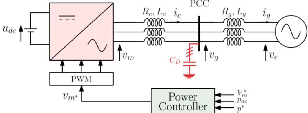
Figure II-1 Representation of a VSC connected to an AC system ... 16
Figure II-2 Single phase quasi static model of the VSC connected to the grid .... 18
Figure II-3 phasor representation of the studied system ... 18
Figure II-4 Principle of the open loop power control with the current controlled mode ... 19
Figure II-5 Principle of the closed-loop power control with the current controlled mode ... 19
Figure II-6 General principle of the grid-following control. ... 20
Figure II-7 Principle of the closed-loop power control with the voltage controlled mode ... 21
Figure II-8 General principle of the grid-forming control. ... 22
Figure II-9 Structure of SRF-PLL ... 23
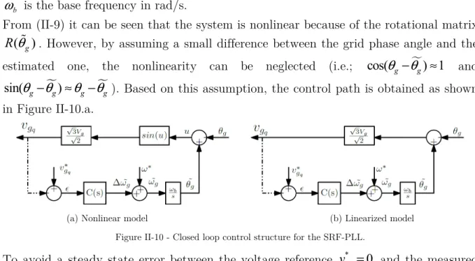
Figure II-10 Closed loop control structure for the SRF-PLL. ... 24
Figure II-11 SRF-PLL dynamics. ... 25
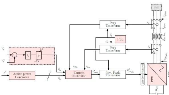
Figure II-12 Grid-following control structure ... 26
Figure II-13 Power controllers (a) Active power, (b) Reactive power. ... 26
Figure II-14 Time-domain simulation of grid-following control (T5%R =100 )ms . ... 27
Figure II-15 VSC outer controllers. ... 27
Figure II-16 Grid-following control structure with various control configurations 29 Figure II-17 Instability phenomenon of the grid-following converter under very weak grid conditions ... 29
Figure II-18 pac m(δ ) curve (Vm=Vg=1 p.u) ... 31
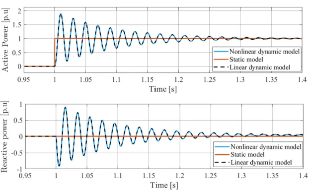
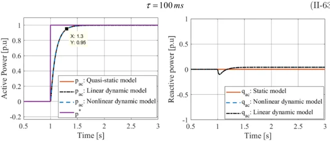
Figure II-19 Comparison between, static, nonlinear dynamic and linearized dynamic model. ... 34
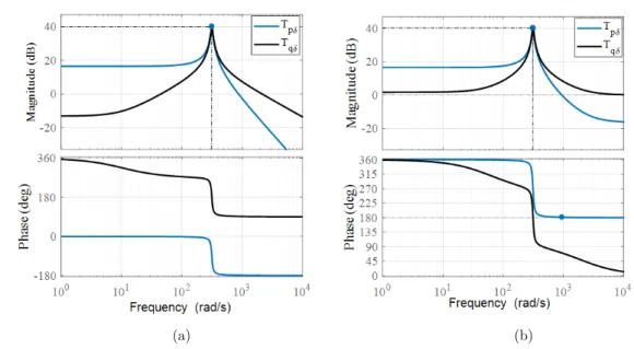
Figure II-20 Frequency response of Tpδ and Tqδ at two different operating point, (a)pac= 0 p.u, (b)pac = 1 p.u. ... 35
Figure II-21 Frequency response of Tpδ and Tqδ with VR ... 36
Figure II-22 Transient virtual resistor (TVR) ... 37
Figure II-23 Frequency response of Tpδ and Tqδwith TVR ... 37
Figure II-24 Grid current dynamics enhancement using the transient virtual resistor ... 38
xv
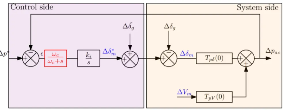
Figure II-25 Partial model of a converter with a grid-forming control ... 38
Figure II-26 Time-domain simulation of a grid-forming active power control ... 39
Figure II-27 Active power feedback control including a low-pass filter ... 40
Figure II-28 Impact of a low-pass filter introduced on the measured active power. ... 41
Figure II-29 Active power feedback control including a low-pass filter ... 41
Figure II-30 Impact of the low-pass filter position. ... 41
Figure II-31 Studied system with dissociation between VSC and AC grid sides. .. 42
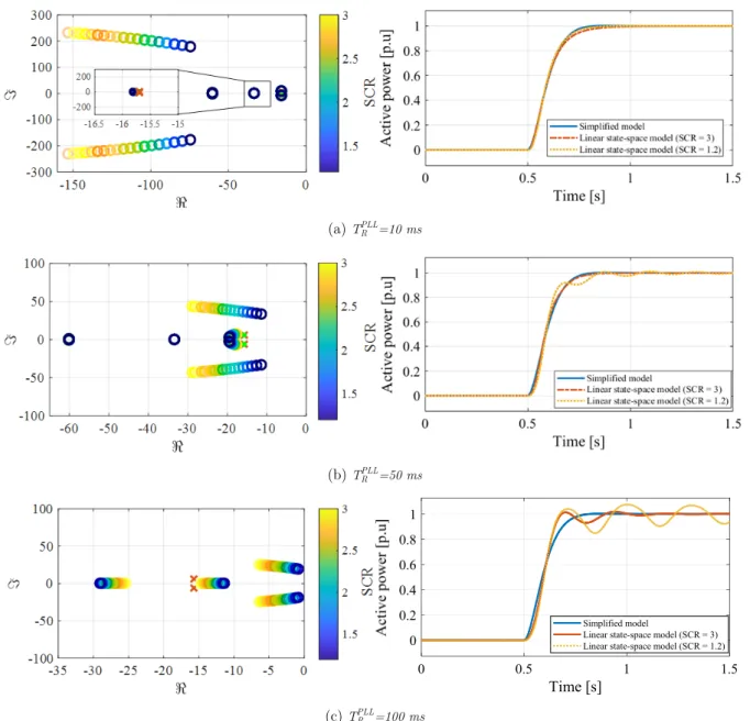
Figure II-32 Linear state space model validation (SCR = 10 and TRPLL=10 ms) ... 43
Figure II-33 Active power dynamics and stability in very weak grid conditions (X) simplified model (O) Linear state-space model ... 44
Figure II-34 (a) Comparison between linear and nonlinear models (b) SCR with respect with the operating point ... 45
Figure II-35 Vector diagram for power coupling in weak grids p*=1 p.u. ... 46
Figure III-1 AC voltage-controlled VSC connected to an equivalent AC grid with variable frequency ... 48
Figure III-2 Active power dynamics with respect to the p* setpoint change. ... 50
Figure III-3 Frequency dynamics with respect to the p* setpoint change ... 50
Figure III-4 Frequency and active power dynamics with respect to the a load change ... 52
Figure III-5 Frequency dynamics with two grid inertia constants ... 53
Figure III-6 Block diagram representation of the overall system ... 53
Figure III-7 The simplified representation of the grid frequency dynamics ... 54
Figure III-8 Validation of the simplified model ... 54
Figure III-9 RoCoF = 5 Hz/s ... 55
Figure III-10 RoCoF = 12.5 Hz/s ... 55
Figure III-11 Active power transient for different values of PR ... 56
Figure III-12 Active power reference saturation ... 57
Figure III-13 Impact of the power reference saturation on the active power and frequency ... 57
Figure III-14 Active power transient with different SCRs ... 58
Figure III-15 Power controller with inertial effect ... 59
Figure III-16 VSC connected to a fixed-frequency AC system ... 60
Figure III-17 Quasi-static active power regulation ... 60
Figure III-18 Comparison between the simulated model, the linear model and the simplified model. Simulation parameters: ki = 1.5 p.u, ωc= 31.4 rad/s and SCR = 3 ... 62
Figure III-19 The couple ki−ωc that ensures HVSC = 5s ... 63
Figure III-20 Impact of the couple ki−ωc on the active power damping and response time ... 63
Figure III-21 Active power and frequency dynamics based on new set of parameters (SCR = 20) ... 64
xvi
Figure III-22 Eigenvalues evolution with respect to the SCR. ‘O’ refers to the full
dynamic model, ‘X’ refers to the developed simplified model ... 64
Figure III-23 Active power dynamics under different SCR values ... 65
Figure III-24 Active power dynamics with respect to the active power setpoint change. ... 68
Figure III-25 Frequency dynamics with respect to the p* setpoint change ... 68
Figure III-26 Bode diagram of the developed models ... 68
Figure III-27 Block diagram to describe the grid frequency dynamics ... 69
Figure III-28 Theoretical model validation of a system subjected to a load change. ... 69
Figure III-29 Block diagram to describe the grid frequency dynamics in response to a load change ... 70
Figure III-30 Active power requested to compensate the power unbalance during the transient ... 70
Figure III-31 Control structure of “Strategy C” ... 71
Figure III-32 Simplified VSC connected to an AC system ... 72
Figure III-33 Quasi-static active power regulation ... 72
Figure III-34 Validation of the simplified model ... 73
Figure III-35 Controller positions ... 74
Figure III-36 Damping evolution of active power oscillatory modes in respect with the controller parameters ... 75
Figure III-37 Improvement of the active power dynamic behavior with HVSC=5s. SCR = 20 ... 75
Figure III-38 Dominant eigenvalues evolution with respect to the AC grid stiffness, ‘O’ refers to the full linear dynamic model, ‘X’ refers to the developed simplified model ... 76
Figure III-39 Active power dynamics under SCR = 1.2. The operating point is set to 1 p.u ... 76
Figure III-40 Block diagram to describe the grid frequency dynamics in response to a load change ... 77
Figure III-41 Comparison between “Strategy B” and “Strategy C” in terms of a grid supporting ... 77
Figure III-42 Interconnection of two VSCs based on different control strategies ... 78
Figure III-43 Transient behavior of power converters following a load change. (1) Test case 1, (2) Test case 2, (3) Test case 3, (4) Test case 4, (5) Test case 5, (6) Test case 6 ... 79
Figure IV-1 2-Level voltage source converter connected to the AC system through an LCL filter ... 83
Figure IV-2 Cascaded inner control structure ... 84
Figure IV-3 Inner control of 2-Level voltage source converter ... 85
Figure IV-4 (a) Output AC voltage control and the Cf circuit modeling (b) simplified modeling of the voltage loop ... 86
xvii
Figure IV-5 2-Level voltage source converter operating in various grid topologies
... 87
Figure IV-6 Dynamics of AC voltage ... 87
Figure IV-7 Participation of state variables on λ5-6 ... 89
Figure IV-8 Impact of current loop dynamics ... 89
Figure IV-9 Proposed method for controllers tuning ... 90
Figure IV-10 Poles location based on the conventional method and the proposed one ... 91
Figure IV-11 AC voltage dynamics based on the new controllers gains ... 91
Figure IV-12 Quasi-stationary control for AC voltage drop across the filter Lf .... 93
Figure IV-13 Active damping for LCL filter ... 93
Figure IV-14 Tuning of the Active damping resistor ... 94
Figure IV-15 Direct AC voltage control ... 94
Figure IV-16 Active power setpoint change and its impact on the AC voltage ... 95
Figure IV-17 Impact of the model reduction on the dominant mode location ... 96
Figure IV-18 Inner and outer loop decoupling based on Strategy C ... 97
Figure IV-19 Inner and outer loop decoupling based on cascaded control structure ... 98
Figure IV-20 Inner and outer loop decoupling based on Direct AC voltage control ... 99
Figure IV-21 Modular Multilevel converter (MMC) ... 100
Figure IV-22 Modular Multilevel converter representation in (abc) frame ... 101
Figure IV-23 Energy control ... 102
Figure IV-24 AC voltage-controlled MMC ... 103
Figure IV-25 Operation of the MMC in two extreme grid topologies ... 104
Figure IV-26 Dynamic performances of the MMC in both grid-connected and autonomous modes ... 105
Figure V-1 CSA and AC voltage PI controller with anti-windup ... 109
Figure V-2 Grid-forming 2-Level VSC based on cascaded control structure and CSA ... 109
Figure V-3 Threshold current loop ... 110
Figure V-4 Grid-forming VSC based on direct AC voltage control and CSA.... 111
Figure V-5 Virtual impedance principle ... 112
Figure V-6 Grid-forming 2-Level VSC based on VI ... 113
Figure V-7 Grid-forming 2-Level VSC and MMC-VSC based on VI ... 113
Figure V-8 System dynamics during a symmetrical three-phase fault ... 114
Figure V-9 Strategy C without inertial effect ... 114
Figure V-10 Simplified quasi-static grid-forming model in unsaturated mode .... 115
Figure V-11 pmes( )δm diagram of a droop control based VSC without inertial effect ... 115
Figure V-12 Simplified quasi-static grid-forming model including the VI ... 116
xviii
Figure V-14 pmes( )δm diagram of a “Strategy C” based VSC and current saturation
algorithm ... 118
Figure V-15 Comparison between critical clearing time for VI and CSA ... 119
Figure V-16 Dynamic pmes( )δm curve of the VSC based on droop control and VI ... 120
Figure V-17 Dynamic pmes( )δm curve of the VSC based on droop control and CSA ... 120
Figure V-18 pmes( )δm diagram of “Strategy C” based VSC with inertial effect (without current limitation) ... 121
Figure V-19 pmes( )δm diagram of “Strategy C” based VSC and VI with inertial effect ... 121
Figure V-20 Dynamicpmes( )δm curves obtained from time-domain simulations with H=5s ... 122
Figure V-21 Comparison between CSA, VI and HCLC ... 124
Figure V-22 Operation sequences of the HCLC ... 124
Figure V-23 Transient stability with and without variable droop control ... 125
Figure V-24 Comparison of the system dynamics for 75ms fault duration with constant and variable droop gain. ... 126
Figure V-25 Impact of the 1st solution on the system dynamics during a phase shift ... 126
Figure V-26 Dynamic comparison between the 1st and 2nd solution based on variable droop control ... 127
Figure V-27 Impact of the 2nd solution on the high inertia system subjected to a three phase bolted fault ... 128
Figure V-28 Implementation of the post-fault algorithm for “Strategy A” and “Strategy B” ... 129
Figure V-29 Dynamic comparison between outer control strategies based on 2nd solution in case of a three-phase fault and phase-shift ... 129
Figure V-30 Single bus case study used to check the stability and the ability to withstand large transients after a short circuit fault followed by a line tripping. Fault occurred t = 1.5 s. After 400 ms both 25 km lines are disconnected. ... 130
Figure V-31 AC signals and converter frequency of a single 2-Level converter during a three phase short-circuit and subsequent line opening. ... 131
Figure V-32 AC signals and converter frequency of a single MMC during a three phase short-circuit and subsequent line opening. ... 132
Figure V-33 Three bus test case to study the compatibility of different controls and robustness of the system following grid events such as short-circuit, disconnecting a line, loss of unit and brutal connection of converters ... 133
xix
Figure V-34 AC signals and converter frequency of a multi-converter grid
topology during a three phase short-circuit and subsequent line
opening. ... 133
Figure VI-1 Small-scale experimental bench... 136
Figure VI-2 Functional scheme of small-scale VSC connected to AC system [155] ... 137
Figure VI-3 dS1005 internal architecture ... 138
Figure VI-4 Connection between (a) CiNERGIA adaptation board and (b) dSPACE boards ... 138
Figure VI-5 Fault generator ... 139
Figure VI-6 PHIL application – Irish power system example ... 139
Figure VI-7 Structure of the RT Lab model ... 140
Figure VI-8 Irish Transmission system –Year 2016 [156] ... 141
Figure VI-9 Model of generators: voltage source with inertia ... 142
Figure VI-10 Structure of simulation for Irish grid with 6 processors ... 142
Figure VI-11 SCADA and RTS interconnection ... 143
Figure VI-12 Three node test case HMI illustrations ... 143
Figure VI-13 Synchronization process of grid-forming converters ... 144
Figure VI-14 Single converter connected to an emulated AC grid and a resistive load ... 145
Figure VI-15 Strategy A ... 146
Figure VI-16 Strategy B ... 147
Figure VI-17 Strategy C ... 147
Figure VI-18 Strategy A ... 148
Figure VI-19 Strategy B ... 148
Figure VI-20 Strategy C ... 148
Figure VI-21 Strategy A ... 149
Figure VI-22 Strategy B ... 149
Figure VI-23 Strategy C ... 149
Figure VI-24 Three-phase short circuit in islanding mode ... 150
Figure VI-25 Three-bus system ... 151
Figure VI-26 Load change ... 151
Figure VI-27 Active power change on VSC 1 ... 152
Figure VI-28 Three-phase fault followed by a tripping line ... 153
Figure VI-29 SCADA HMI ... 153
Figure VI-30 Dynamic behavior of the power system during a loss of the generator G4 ... 154
xx List of Tables
Table I-1 Technical needs [20] ... 6 Table II-1 Base quantities ... 17 Table II-2 Typical system parameters ... 25 Table II-3 Control parameters ... 25 Table III-1 Simulation parameters ... 49
Table III-2 Characteristics of the frequency dynamics with high and low grid
inertia constant ... 52 Table III-3 Eigenvalues and zeros of the 1st and 2nd models ... 67
Table III-4 Characteristics of the frequency dynamics with high and low inertia
constant ... 69
Table III-5 Characteristics of the frequency dynamics with and without droop
control ... 70 Table III-6 Distributed line parameters ... 77
Table III-7 Functionalities and performances of control strategies ... 80
Table IV-1 System and control parameters ... 83 Table IV-2 System and control parameters ... 87 Table IV-3 System eigenvalues ... 89 Table IV-4 Controller gains ... 91 Table IV-5 System eigenvalues ... 95 Table IV-6 PARTICIPATION FACTORS (NORMALIZED) ... 97
Table IV-7 System and control parameters ... 104 Table V-1 System and control parameters ... 113
Table V-2 Comparison between different algorithms for current limitation ... 122
Table V-3 Comparison between different algorithms for current limitation ... 123
Table VI-1 Real Time simulation characteristics ... 139
Table VI-2 Synthesis of elements of Irish grid RT-LAB model ... 142
1
I.
Introduction to a power system based 100%
power electronics
I.1 Context and motivation
Toward a 100% Renewable Electrical Grid: The transition to a renewables-based energy system is already under way. The last decade has seen the cost of renewable energy decline continuously, making it cost-competitive compared to conventional energy in many parts of the world. Since 2009, the module prices for solar photovoltaics (PV) have fallen by around 80%, while wind turbine prices have declined by 30-40%, making the business case for renewable energy stronger than ever before (IRENA, 2017) [1]. The most crucial benefits of transitioning to a 100% renewable energy system is the resulting large reduction of greenhouse gas (GHG) emissions. To achieve this global warming limit, the IPCC (Intergovernmental Panel on Climate Change) highlights the need for a rapid energy transformation based on a significant increase of renewables (IPCC, 2018). Several countries already come close to achieving this goal. Iceland, for instance, supplies 100% of its electricity needs with either geothermal or hydropower. Other countries that have electric grids with high fractions of renewables based on hydropower include Norway (97%), Costa Rica (93%), Brazil (76%), and Canada (62%). Hydropower plants have been used for decades to create a relatively inexpensive renewable energy, but these systems are limited by natural rainfall and geographic topology. In many countries, most good sites for large hydropower resources have already been developed, which requires a transition to intermittent renewable energy sources (IRES) (i.e., wind and solar photovoltaic systems). Countries such as Denmark, Ireland, and Germany have massively installed intermittent renewable energy systems and are operating with annual penetrations of more than 20% at the national level [2]. Some scenarios from the European Wind Energy Association show that over the next ten years, wind energy could meet one-fifth of the electricity demand in Europe by 2020, one-third by 2030, and half by 2050 [3]– [5].
A number of studies have excluded nuclear, carbon capture and storage technologies to investigate whether power systems could rely on 100% renewable energy sources, such as those for Denmark, Netherlands, Germany, France, Ireland, Portugal [6]–[10]. Although the first trends do not indicate the feasibility of a 100% renewable power, due to intermittent generation of the power sources, however, the residual demand not supplied by the IRES can be compensated by one of the dispatchable generation technologies, storage systems or the inertia stored in the mechanical part of the wind turbines.
A power system based 100% intermittent renewable energy is still a subject to investigate. Nevertheless, a scenario with an area of the present power system supplied occasionally with 100% intermittent renewable sources is of high likelihood. Actually,
2 since wind and photovoltaic generations are concentrated where the wind blows and the sun shines respectively, a large area of the power transmission system may lose the last synchronous link connecting it to the rest of the system as illustrated by Figure I-1. In such a situation, the transmission grid operators must adapt their practice to run the islanded system with no synchronous generation, under sufficient reliability.
Figure I-1 - Representation of the present power system losing its last synchronous link
Apart from the issues related to the primary energy source, the management of this energy itself remains a major issue and where power electronics play a fundamental role.
Power System and Power Electronic Converters: Power electronic converters have been developed for decades with many types of applications. One of the first applications is the drive of electrical machines mainly used for industrial applications. The beginning of the renewable energy story had a moderate influence on the power electronic converters market. Very quickly, the connection of wind turbines and photovoltaics through power electronic converters becomes compulsory. In addition, some new transmission links had to be established in order to transmit the renewable energy from the area where it is generated to the area where it is consumed. Another reason is the market incentive. In Europe, ENTSO-E, the European Network of TSOs for electricity is planning the future grid with the Ten Years Network Development Plan, (TYNDP) [11], where, a lot of new HVDC links are mentioned as highlighted on the map in Figure I-2.
3
Figure I-2 - HVDC links in Europe [11]
These factors (i.e., increase of IRES and HVDC links) result in a significant increase of power electronic converters in the current power system. Two types of power converters topologies exist in the present power system: the Voltage Source Converter (VSC) based on transistor technology and Current Source Converter (CSC) based on thyristor technology, also called Line Commuted Converter (LCC). Indeed, before using transistors for the drive of DC or synchronous motor, the thyristor based-power converters were connected to a current source. Due to the operating mode of the thyristors, the current source operation mode was compulsory. When switching to transistor-based-power converters, both choices i.e., current source or voltage source were available. This choice had an influence on the type of switches, a CSC is supposed to use a switch composed of a transistor in series with a diode, whereas the VSC needs a transistor in parallel with a diode as shown on Figure I-3.
In case of a CSC, the two switches in series induce more losses than in the case of a VSC. The VSC has been chosen for its efficiency and because it is easier to manage a voltage source with a capacitor than a current source with an inductor.
a) VSC b) CSC
4 A converter is always a double modulator of electrical quantities. In the case of a VSC,
the DC bus voltage u is modulated to generate a set of three voltages on the AC side, dc
but at the same time, the AC grid currents are modulated to generate the DC current
i . Thus, this topology could either be called “DC voltage source converter” or “AC m
current source converter”. The modulation is intrinsically symmetrical. However, in practical applications, only one modulation is used, i.e., the voltage modulation to control the AC currents. This is the reason why this converter is named “Voltage Source Converter”.
For high power applications, the DC bus voltage is limited by the technology of the cables. For several years, the nominal voltage for the DC cable had to be set to 320 kV between one pole and the ground. Now, some new projects are expected with higher voltage of 400 kV to 525 kV. In all cases, this voltage is supposed to put hundreds of transistors in series. Switching hundreds of transistors at the same time is extremely challenging [12], the concept of a Voltage Source Modular Multilevel Converter (VSC-MMC) is a solution to this issue. It is based on a series connection of elementary submodules, which do not switch at the same time. Submodules may use a half-bridge, full-bridge or hybrid topologies [13].
A stack of N-submodules is called an arm. Each arm is connected to an inductor (Larm,
arm
R ) whose aim is to limit the derivative of the current in case of a DC fault. Each
phase comprises two identical arms. One is connected to the positive pole of the DC bus and the other is connected to the negative pole of the DC bus. The combination of two arms in the same phase is called a leg. The MMC is composed of three legs (see Figure I-4). The series connection of hundreds of elementary submodules results in a quasi-sinusoidal modulated voltage waveform as shown in Figure I-4.
Figure I-4 - Modular Multilevel Converter
Control management of power electronic converters: When the power injected by these power converters is not negligible with respect to the nominal power of the system at the point of common coupling, the grid quantities can be significantly
5 affected. As a consequence, power converters cannot be considered as simple devices connected to the main grid, but they will actively participate in supporting the grid and affecting its stability. Hence, it is important to monitor the grid-connected power converters by estimating their states (e.g.; angle, voltage …), and also to manage their power exchange. The fundamental aim of power converters is to inject the power coming from wind and solar or planed on HVDC links to the main grid. This aim is fulfilled through an adequate control management i.e., power converters require first to be synchronized to the main grid, then injecting the power. The purpose of the grid synchronization stage is to determine the phase angle of the grid voltage to control the power exchange between the AC and DC systems, then, the exchanged power dynamics are specified by a power control stage. Therefore, effective grid synchronization algorithms in addition to an adequate power management are key factors determining the complete control structure quality.
Conventional Grid-following Control: Today, power converters are controlled under the presumption that an AC voltage with a given magnitude and frequency is maintained at their terminals which they can simply follow to inject a controlled power. In practice, this translates into the assumption that the AC system is dominated by synchronous generators forming the instantaneous AC voltage. This control strategy is well-known as a grid-following control. If a part of the AC grid dominated by renewable energy sources is disconnected from the main AC grid due to a fault or line tripping, it will lead to a loss of synchronism because of the absence of an AC voltage to follow.
Another consequence of the increase of the grid-following based-converters proportion is the decrease of the total grid inertia [14], which induces a faster dynamic response of the frequency [15]. The low-inertia phenomenon has been already noticed in several areas, such as Ireland and UK. More details about those data are published by ENTSO-E [16]. Actually, a “Synthetic inertia” concept has been proposed for grid-following converters. However, because of the frequency estimation delay and control response time, this concept is not as efficient as a real inertia to limit the frequency derivative [17]. Moreover, since synthetic inertia control uses the frequency derivative to emulate the inertial effect, this induces more noise that may disturb the system operation and endanger the system stability.
Another limitation of grid-following converters is their inability to operate correctly under weak grid conditions and especially to respond to the fault-ride through (FRT) requirements [18]. In fact, large wind farms are usually located in remote and offshore areas. High voltage transmission systems that have long transmission distances are used to deliver wind power to main grids. Long transmission lines or cables result in a high grid impedance, and thereby, a weak AC grid. Many studies show that the operation of grid-following converters is limited and highly sensitive under weak grid conditions. Hence, an acceptable operation with desired performances cannot be guaranteed. [19]. Moreover, in case of a fault, the grid-code requires a full reactive
6 current injection to support the AC voltage. However, in the case of an islanded wind turbine platform, where no reactive power is demanded, this may not be the right
choice. Because of all these reasons and to avoid several limitations of the
grid-following control, some countries such as Ireland made a choice to limit the integration of grid-following converters in their grid to 60 percent [20], [21].
To anticipate and prepare for these challenges, the way to control power converters has to be changed in order to meet system needs as with a synchronous machine.
Power Electronic Converters and System Needs: The system needs listed in Table I-1 have been guaranteed until now thanks to the physical characteristics of SGs. For instance, SGs have inertia because of their rotating mass that compensates a power imbalance during transients. Power converter devices have not got any, and therefore, they require storage systems with adequate control laws. Another example is the overcurrent capability that is larger for SG than for power electronic converters. Actually, semiconductor components could be oversized to deal with overcurrent issues. However, this engenders additional cost and weight, making the installation of station based power converters less beneficial. Moreover, power converters are currently controlled as current sources. They do not impose their own voltage like SG. Consequently, they cannot operate in standalone mode.
Table I-1 Technical needs [20]
Service Main technical functions Conditions
Electrical energy transport on AC line
Three-phase sinusoidal currents injection
ω < ω < ω
Parallel load connection Control of grid nodes RMS
voltages
V < V(i) < V
System safety Load-sharing between
parallel generators
∑P (i) = P
Hardware Security Overcurrent limitation I (i) < I
In the near future, power converters will dominate the AC system and replace SGs. Thus, they are asked to impose an instantaneous AC voltage at their terminals, while fulfilling the same transmission system requirements as conventional SGs. This capability of power converters is known as “grid-forming” that necessitates a change in the way the converters are controlled today.
I.2 State-of-the-art: From grid-following to grid-forming
ENTSO-E is currently working on a new version of this grid code which will embed the notion of grid-forming converters. A working group has already published a technical report document called “High Penetration of Power Electronic Interfaced Power Sources and the Potential Contribution of Grid-Forming Converters” on this topic. It defines several subtopics of concern which are to be examined.
7
• Creating system voltage
• Contributing to fault level
• Sink for harmonics
• Sink for unbalance
• Contribution to inertia
• System survival to allow effective operation of Low Frequency Demand
Disconnection (LFDD)
• Preventing adverse control interactions
Referring to the literature, to make power converters have grid-forming capability, a droop control method also called inverse-droop control for synchronization [22] and power regulation has been proposed to imitate the parallel operation characteristics of SGs. It was originally proposed in [23] for uninterruptible power supply (UPS) systems, and has been developed into a general approach for parallel converters [24], especially in Microgrid [25]–[31] and UPS systems [32], [33]. Thereafter, several variants of droop control have been proposed to improve the system dynamics [34] and to be applied in low voltage grids, in which the line impedance is more resistive [35]. Moreover, a virtual frequency-voltage frame method is proposed to solve this problem in any given
condition of line impedance R/X ratio [36]. On the other hand, P-ω droop can still be
applied in LV grids by adding virtual output impedance to make the total line impedance more inductive [37]–[39], to improve the active power dynamics and to ensure a decoupling between active and reactive power [40]. Additionally, it has also been demonstrated that optimization of the droop coefficient [41] can help to enhance system stability. Contrary to the secondary and tertiary controls that need communication signals from a central controller [42] [43] [44], the primary droop control allows a power sharing in parallel operation only based on load measurements and without communication.
Despite the benefits of the droop control strategies, it still has no inertia emulation capability, which limits their applicability to small-scale power system. A low-pass filter is added to droop control allows emulating the inertial effect [45]–[47] similarly to a SG. However, this yields an oscillatory behavior of the system [46]. Therefore, another promising solution that replaces the conventional droop control has been proposed to mimic not only the steady state characteristics of SGs, but also their transient characteristics, by applying swing equation to enhance the inertia. Different implementations have been proposed in the literature such as Virtual Synchronous Generator (VSG) [47], [47]–[49], Synchronverter [50]–[54], virtual synchronous machine (VSM) [27], [45], [55]–[59] and VISMA [60], but all of them adopt the idea of controlling the converter to mimic an actual SG by using its corresponding models. In this way, a converter performs equivalent to an SG, especially in terms of inertia response [61], [62]. Therefore, the VSG can play an important role in more power electronic based power systems in the future. In recent work, it is reported that additional lead-lag unit allows the conventional droop control to contribute to total
8 inertia of the system and improve the system damping [46], [47], and make it mathematically equivalent to the VSG [46]. However, this analogy is only true under many assumptions that have not been discussed in the literature.
Apart from the VSG and the droop control, other control laws allowing the grid-forming capability have been proposed: Virtual Oscillator (VOC) [63]–[68], matching control [10] and Inducverter [69]. It has been proven that the VOC is equivalent to conventional droop control from a small-signal sense [64], [65], [70]. However, this control may be more advantageous in the case of voltage unbalance and distortion due to its non-linear characteristic [64], [68]. The Matching control is another way to emulate the SG, by creating through the control, a link between the DC bus and the frequency, where the moment of inertia will be equivalent to DC capacitor and the DC voltage will be equivalent to the rotation speed. This technique is controlling the frequency through the variation of the DC voltage. Therefore, the control of the DC side with a proportional controller is mandatory. Thanks to the link between the DC bus and the frequency, the load sharing capability can be achieved similarly to the conventional droop control, where the droop frequency gain is equivalent to the proportional controller gain. The main drawback of such controller is the all-in-one features, i.e., (DC voltage, grid-frequency control, power sharing and the active power control) managed with only one degree of freedom. The last algorithm, the Inducverter refers to the emulation of the induction machine characteristics, where converters can be synchronized to the main grid without considering its initial frequency. However, the emulation of this control may result in some numerical issues due to the derivative action in the model of the machine.
Some of these controllers such as VSG are using the PLL, whereas, the droop control, the filtered droop control, virtual oscillator, matching control and Inducverter are not using the PLL. For some authors [20], the PLL-less option is advantageous to avoid the numerous stability issues caused by the PLL with the classical grid-following control [20], whereas, other authors affirm that the PLL has no major impact on the steady-state operation, and its utilization is limited to damping purposes [58]. Neither affirmation has been theoretically proven.
9 Recently, a novel concept allowing power converters to operate in islanded mode while being a current source has been proposed in [71], [72]. The development of this control was motivated by the following reason: the blocking state of the HVDC offshore converter illustrated in Figure I-5 yields a distortion of the 155 kV point and its increase roughly by 30%. This behavior was linked especially to the way the current loop is implemented for the GSC (Grid Side Converter). This behavior has been avoided by proposing a direct AC voltage control with a transient damper for the grid current.
In control hierarchy, two different control layers for power electronic converters are characterized as depicted in Figure I-6 : The outer control is linked with the system level, and the inner control interacts with the device level.
Figure I-6 - Local control hierarchy
In most of the references cited previously, except in [71], the focal points were on the outer loop control and its interaction with the system level. Other researches were mainly interested in the design and the control of the inner control loops. Actually, one common solution to control the AC voltage is based on the cascaded PI controller structure. This solution is favored for industrial applications because of the simplicity of its implementation, and also because it generates a current reference that serves to protect the converter [73]. Apart from the conventional cascaded PI controllers [28], [34], [73]–[77], other control strategies have been used such as sliding mode control for
inner current loop and a mixed H2/H∞ for AC voltage loop [78], fractional order
controller [79] and LQR technique [80]. The method in [78] aims to design a robust controller in order to achieve high performances, however, this technique is complex and requires very high computation effort. The method in [79], has been motivated by its flexibility and its high number of degrees of freedom, and finally, the method in [80] has been motivated by its simplicity. Moreover, it achieves a desired voltage bandwidth. Among the inner control strategies proposed for grid-forming converters, a few studies have discussed the control design in high power applications [73], [78],
10 where the switching frequency is lower than 5kHz. Such conditions can result in slow dynamics [73], restrained stability regions and interactions between control loops, which can lead to an unstable system [81]. Therefore, controller parameter tuning in such conditions is still a challenge.
Contrary to 2-Level VSC, MMCs do not require an output LC filter, and therefore, no compulsory need for AC voltage regulation loops. The modulated voltage can be directly driven by a set of AC voltages. However, the MMC contains internal capacitors in each submodule, which require some internal loops to control the energy. The dynamics of these loops are close to those of the outer loop, which may cause interactions between controllers. This question has not been investigated in the literature.
Grid-forming converters are operating as a voltage source behind impedance, and thus, they are very sensitive to grid disturbances that may engender overcurrent. The current-limiting strategies of grid-forming VSCs during large disturbances have been studied in many references [22], [82]–[89]. Among these works, few references extend the current limitation studies to the large power system [87], where other events can cause overcurrent issues such as line tripping and reclosing. Two main strategies have been proposed for grid-forming converters in order to limit the current during transients. One solution is to limit the current with a current saturation algorithm (CSA) [82], [83], [88]. The second solution is the Virtual Impedance (VI) [71], [84]–[86], [90], [91]. It has been implemented to emulate the effect of physical impedance when the current exceeds its nominal value. This control strategy intended to modify the AC voltage reference in order to limit the current. Therefore, its reaction against the fault depends on the AC current as well as on the dynamics of the AC voltage regulators. For slow inner control dynamics, the virtual impedance cannot guarantee a current limitation during the fault. A feed-forward action on the modulated voltage has been proposed to deal with this issue [87]. Once the current is limited, the post-fault synchronization is of highest interest. However, the impact of the current limitation techniques on the transient stability has been marginally studied in the literature [92]– [97]. Indeed, an unstable behavior when the overcurrent protection is disabled would lead to an unavoidable trip from the main grid for safety purposes [18]. However, in future power systems, different power sources have to cope with various events and guaranty the stability. In this context, the transient stability of the system is defined as the ability of the power converter to recover the synchronism after fault clearing. The choice of the current limiting algorithm has a large influence on the transient stability. In [92], [95], the transient instability phenomenon using the CSA while keeping the droop control has been studied. To avoid this instability issue, some papers proposed to switch from voltage control, based on the droop control to current control, based on a phase-locked loop [22], [98]. These methods require a complex algorithm for fault detection and triggering conditions. Moreover, as specified by [22], fault recovery could only be achieved after a considerable retuning of the voltage controller and the
11 power controller in order to avoid AC voltage collapse. In [84], the authors showed through time-domain simulations, the ability of the VI to ensure a better transient stability than the CSA in case of a heavy load connection. However, this result has not been theoretically investigated.
To anticipate and prepare for future challenges linked to the high penetration rate of power electronic converters in power transmission systems [16], [99], [100], several European Transmission System Operators (TSO) and universities have gathered to form a European project to work on these issues, e.g., PROMOTioN [101], MIGRATE [102], recently HVDC Inertial Provision [99], etc. Among these projects, the MIGRATE Project is interested in a high integration of power electronic converters up to a 100%. The MIGRATE project that funded this work is presented in the following paragraph.
MIGRATE Project: MIGRATE stands for Massive InteGRATion of power
Electronic devices. It is an EU-funded project under the framework of European
Union’s Horizon 2020. It gathers several partners that are presented in Figure I-7. There are 11 TSO, 12 universities and one manufacturer from 13 countries working together in this project. Their main objective is to propose innovative solutions to progressively adjust the HVAC system operations. The different objectives of the project are addressed in 8 work packages. This PhD is part of the work package 3 that aims at developing controls and operations of a grid with 100% converter-based devices.
12
I.3 Contributions and contextual constraints
The main contributions of this work are listed below:
• Chapter II: Starting from the fundamental goal of a power converter, which aims to provide active power to the main grid, a first grid-forming control structure is derived. It consists of a robust power control loop that allows power converter to guarantee a specified active power dynamics regardless of the AC grid stiffness. In this chapter, the possible coupling between active and reactive power is highlighted and limited through a specific power controller tuning. Additionally, a transient virtual resistor is also implemented to overcome a particular resonance around the grid frequency and damp the grid current dynamics.
The proposed control is equipped with a PLL. It is demonstrated that the use of the PLL in this control is fundamentally different from the grid-following.
• Chapter III: The power converter is connected to an AC system with a variable grid frequency that emulates: the swing equation, the turbine dynamics and the governor of a real synchronous machine. Based on this simple grid case, the active power and frequency dynamics of the first grid-forming solution are studied. Then, two control strategies are derived from the first solution to allow inertia emulation similarly to a SM. The first solution is a PLL based-control and the second one in a PLL-less control. The properties of each control method are highlighted and their impact on the active power and frequency dynamics are deeply analyzed along this chapter.
• Chapter IV: In previous chapters, the converter was connected to the AC
system through an L filter. This consideration simplifies the analysis. However,
its appropriateness is relative to the converter topology. In case of grid-forming 2-Level converters, the connection to the AC grid is usually done through an
LCL filter. This additional LC filter requires additional voltage and control
loops. In this chapter, the impact of the implementation of this filter and its control on system stability is highlighted and new control methods are proposed to improve the system stability, dynamics and guarantee the same performances reached in the previous chapters.
In the case of Modular Multilevel Converters (MMCs), an LC filter is not
required since they generate a quasi-sinusoidal output voltage. However, the main challenge with MMCs, is the energy management on their submodules. In this chapter, the impact of the grid-forming control loops on the energy stored on the MMC is briefly discussed.
• Chapter V: This chapter deals with current limitation in faulted conditions. Two control techniques are presented and their implementation on each inner
13 control strategy is shown. The current limitation methods are compared and their impact on the transient stability is highlighted. Based on this comparison, a hybrid current limitation control is proposed to benefit the advantage of both methods. Additionally, a simple adaptive gain is proposed in order to improve the critical clearing time and hence, the transient stability.
• Chapter VI: To validate the proposed control strategies, a small-scale power converter is developed. Then, the interoperability between the proposed controls is assessed through a Power Hardware In the Loop (PHIL) simulation, where different test cases are performed.
In this thesis, some contextual constraints are considered:
• The solutions must be compatible with the highest voltage, and the highest power rating of existing VSCs.
• The secondary and the tertiary control are not discussed in the thesis.
• With no synchronous generators, the definition of system frequency is no longer linked with the rotation speed of rotors. As a consequence, frequency estimation is unclear, especially under the fundamental period or during transients. Thus, an arbitrary choice constrains the proposed solution not to rely on frequency measurements. This task is handled by another Work Package in the project. • The source of the primary energy is neglected in this thesis.
• Harmonics, nonlinear loads and motor loads are out of the scope of this thesis.
I.4 List of publications derived from this work
The publications resulting from this thesis are listed below. The main contributions presented in this manuscript are based on the journal papers J1-J6, the conference papers C1-C13, a book chapter and different public simulation models..
J1: “Critical clearing time determination and enhancement of grid-forming
converters embedding virtual impedance as current limitation algorithm” IEEE Journal of Emerging and Selected Topics in Power Electronics, 12/2019, QORIA Taoufik, GRUSON François, COLAS Frédéric, DENIS Guillaume, PREVOST Thibault, GUILLAUD Xavier
J2: “Current Limiting Algorithms and Transient Stability Analysis of
Grid-Forming VSCs” Electric Power Systems Research (EPSR), QORIA Taoufik, GRUSON François, COLAS Frédéric, GUILLAUD Xavier
J3: “Classification of Droop-Based Grid-Forming Control Schemes: Application
in Forced Commutated Converter-Based HVDC Systems” Electric Power
Systems Research (EPSR), ROKROK Ebrahim, QORIA Taoufik,
14
J4: “Direct AC Voltage Control for Grid-forming Inverters” Journal of Power
Electronics, QORIA Taoufik, LI Chuanyue Li, OUE Ko, GRUSON François, COLAS Frédéric, GUILLAUD Xavier
J5: “Coupling influence on the dq impedance stability analysis for the
three-phase grid-connected inverter” MDPI Energies, 09/2019, LI Chuanyue Li, QORIA Taoufik, COLAS Frédéric, JUN Liang, WENLONG Ming, GRUSON François, GUILLAUD Xavier
J6: “A PLL-free grid-forming control with decoupled functionalities for
high-power applications” IEEE Access, QORIA Taoufik, ROKROK Ebrahim, BRUYERE Antoine, FRANCOIS Bruno, GUILLAUD Xavier
C1: “Analysis of the coupling between the outer and inner control loops of a
Grid-forming Voltage Source Converter” EPE2020, 09/2020 QORIA Taoufik, GRUSON François, COLAS Frédéric, KESTELYN Xavier, GUILLAUD Xavier
C2: “Impact of grid-forming control on the internal energy of a modular
multi-level converter” EPE2020, 09/2020 ROKROK Ebrahim, QORIA Taoufik, BRUYERE Antoine, FRANCOIS Bruno, ZHANG Haibo, BELHAOUANE Moez, GUILLAUD Xavier
C3: “Current Limiting Algorithms and Transient Stability Analysis of
Grid-Forming VSCs” PSCC 2020, 06/2020 QORIA Taoufik, GRUSON François, COLAS Frédéric, GUILLAUD Xavier
C4: “Classification of Droop-Based Grid-Forming Control Schemes: Application in
Forced Commutated Converter-Based HVDC Systems” PSCC 2020, 06/2020 ROKROK Ebrahim, QORIA Taoufik, BRUYERE Antoine, FRANCOIS Bruno, GUILLAUD Xavier
C5: “Effect of Using PLL-Based Grid-Forming Control on Active Power
Dynamics under Various SCR” IECON'2019-IEEE, 10/2019 ROKROK Ebrahim, QORIA Taoufik, BRUYERE Antoine, FRANCOIS Bruno, GUILLAUD Xavier
C6: “Power Converters Classification and Characterization in Power Transmission
Systems” EPE'19, 09/2019 QORIA Taoufik, PREVOST Thibault, DENIS Guillaume, GRUSON François, COLAS Frédéric, GUILLAUD Xavier
C7: “Tuning of AC voltage-controlled VSC based Linear Quadratic Regulation”
IEEE PowerTech19, 06/2019 QORIA Taoufik, LI Chuanyue Li, OUE Ko, GRUSON François, COLAS Frédéric, GUILLAUD Xavier, PREVOST Thibault
C8: “Inertia effect and load sharing capability of grid-forming converters
connected to a transmission grid” 15th ACDC19, 02/2019 QORIA Taoufik, GRUSON François, COLAS Frédéric, DENIS Guillaume, PREVOST Thibault, GUILLAUD Xavier
15
C9: “Tuning of cascaded controllers for robust grid-forming Voltage Source
Converter” Power Systems Computation Conference, 06/2018 QORIA Taoufik, GRUSON François, COLAS Frédéric, GUILLAUD Xavier
C10: “Development of a power hardware in the loop simulation of an islanded
Microgrid” IECON'19, 10/2019 FAKHAM Hicham, QORIA Taoufik,
LEGRY Martin, DUCARME Olivier, COLAS Frédéric
C11: “Modeling and Control of the Modular Multilevel Converter connected to an
inductive DC source using Energetic Macroscopic Representation” EPE'18, 09/2018 QORIA Taoufik, GRUSON François, DELARUE Philippe, LE MOIGNE Philippe, COLAS Frédéric, GUILLAUD Xavier
C12: “Electromagnetic Transients (EMT) Model Design based on Modular
Multilevel Converter Mockup” The International Conference on Power Systems Transients (IPST2019), 06/2019 BELHAOUANE Moez, ZHANG
Haibo, COLAS Frédéric, KADRI Riad, QORIA Taoufik, GRUSON
François, RAULT Pierre, DENNETIERE Sébastien, GUILLAUD Xavier
C13: “Contrôle du Convertisseur Modulaire Multiniveaux connecté à une source
DC inductive” Symposium de Génie Electrique 2018, SGE 2018, 07/2018 QORIA Taoufik, GRUSON François, DELARUE Philippe, LE MOIGNE Philippe, COLAS Frédéric, GUILLAUD Xavier
Book Chapter: “Converter-based dynamics and control of modern power
systems". Place of publication not identified: ELSEVIER ACADEMIC Press, 2020.
Data I: T. Qoria, U. Markovic, T. Jouini, D. Groß, G. Denis, and T. Prevost.
Data underlying the research of a 3 bus model for full inverter system - Migrate WP3. 2018.