HAL Id: hal-01876231
https://hal.archives-ouvertes.fr/hal-01876231
Submitted on 18 Sep 2018
HAL is a multi-disciplinary open access
archive for the deposit and dissemination of
sci-entific research documents, whether they are
pub-lished or not. The documents may come from
teaching and research institutions in France or
abroad, or from public or private research centers.
L’archive ouverte pluridisciplinaire HAL, est
destinée au dépôt et à la diffusion de documents
scientifiques de niveau recherche, publiés ou non,
émanant des établissements d’enseignement et de
recherche français ou étrangers, des laboratoires
publics ou privés.
Multiple-Input turbo equalization over time-varying
frequency selective channel
Christophe Laot, Raphaël Le Bidan, Dominique Leroux
To cite this version:
Christophe Laot, Raphaël Le Bidan, Dominique Leroux. Multiple-Input turbo equalization over
time-varying frequency selective channel. EUSIPCO 2002 : 11th European Signal Conference, Sep 2002,
Toulouse, France. �hal-01876231�
Multiple-Input Turbo Equalization
Over Time-Varying Frequency Selective Channels
C. Laot, R. Le Bidan and D. Leroux
ENST Bretagne, BP 832, 29285 Brest Cedex, FRANCE
Abstract This paper deals with a low complexity receiver scheme for high order modulation where multiple-input equalization and channel decoding are jointly optimized in an iterative process. Initially proposed in a single-input version the turbo-equalizer is extended for multiple-input. Channel diversity allows performance of the turbo-equalizer to be improved in severe frequency selective environment. Results are presented for 4-QAM and 16-QAM modulations over multipath Rayleigh fading channels.
I. INTRODUCTION
This paper extends the single-input turbo-equalizer [1-2] (SI-TEQ) for multiple receiver antennas allowing channel diversity to be exploited by the equalizer. In turbo-equalization (TEQ), the turbo-equalization and channel decoding are jointly optimized. The first version of the TEQ [3] uses a MAP detector to combat ISI. This receiver gives good performance but is essentially dedicated to weak spectral efficiency modulation and short delay spread channels owing to its prohibitive computational complexity. In order to reduce the complexity of the original TEQ, the MAP detector is replaced by an equalizer based on linear filters.
The paper is organized as follows. Section II describes the transmission model. Section III introduces the MI-TEQ structure, which combines a multiple-input equalizer and a SISO decoder. Section IV provides simulation results for MI-TEQ over multipath Rayleigh fading channels, using 4-QAM or 16-QAM. Section V presents our conclusions.
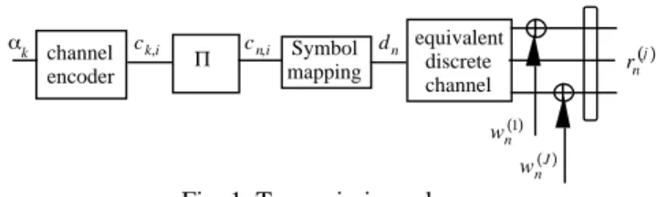
II. PRINCIPLE OF TRANSMISSION SCHEME Let us consider the transmission scheme depicted in figure 1. A rate R convolutional code is fed in by independent binary data k taking the values 0 or 1 with the same probability. A
random interleaver Π is fed in by the coded data ck, i ∈ ±
{ }
1and provides interleaved coded data cn,i. Each set of 2m
coded data cn,i; i=1,..., 2 m is associated with M-ary
complex symbol dn=
(
an +jbn)
where symbols an andbn with variance
2
2 take equiprobable values in the set
±1,±3,...,±
(
M−1)
{
}
with M =2m. Symbols dn withduration T have unitary variance d
2 . channel encoder Symbol mapping equivalent discrete channel k wn( )1 wn J ( ) ck,i cn,i dn rn( )j Π
Fig. 1. Transmission scheme
The received signal is modelled by a single-input multiple-output (SIMO) equivalent discrete time channel where each output j; j=1,..., J is corrupted by an additive, zero-mean,
white Gaussian noise (AWGN) wn j
( ) with variance j
2
. The receiver antenna j observes the input rn
j ( ) equal to rn j ( )= h n, l j ( )d n−l+wn j ( ) l=0 L( )j
∑
j=1,..., J (1) where hn, l j ( ) are the L( )j+1 coefficients of the equivalent
discrete time channel seen at the antenna j at the time n . The transfer function of this channel is given by
Hn j ( )
( )
z = h n, l j ( )z−l l=0 L( )j∑
(2)The coefficients of the SIMO channel are supposed normalized to obtain a unitary average power at the input of the receiver n = hn,l j ( )2 l=0 L( )j
∑
j=1 J∑
with E{ }
n =1 (3)When the noise components wn j
( ) are supposed independent,
the variance of the noise at the input receiver is equal to
b 2 = j 2 j=1 J
∑
(4)The signal to noise ratio (SNR) at the turbo-equalizer input is equal to SNR= d 2 b 2 = R E b N0log2
( )
M (5)where E b is the average received energy per information bit,
N0 the one-sided noise power spectral density at the input of
III. MULTIPLE-INPUT TURBO-EQUALIZER For the TEQ, equalization and channel decoding are jointly performed in an iterative way as for a turbo-code [4]. Each iteration p ; p=1,..., P is carried out by a module fed in by
both received signal samples rn j
( ) and estimated data d n
originating from the module p
(
−1)
.As depicted in figure 2, each module consists of an multiple-input equalizer, a symbol to binary converter (SBC), a deinterleaver Π−1, a soft-input soft-output (SISO) binary decoder, an interleaver Π and a binary to symbol converter (BSC). Each module p delivers an estimate of the symbol dn, called d n, to be used by the equalizer of the module
p+1. delay rn( )j SBC Π−1 SISO decoder BSC d n d n Π multi-input equalizer
Fig. 2. Structure of the module p A. Multiple-input equalizer structure
The structure of the equalizer is depicted figure 3. The multiple-input equalizer combines the outputs of the feed forward J transversal filters fed in by the SIMO channel. The intersymbol interference at the combiner output is suppressed by the output of a feedback filter fed in by the estimated symbols d n provided by a previous processing.
When the estimated data are equal to the transmitted symbols, this equalizer is a multiple-input Interference Canceller (IC) which allows ISI to be completely removed. The transmitted symbols are generally unknown by the receiver. As a consequence, the equalizer is sub-optimum and it will be necessary to determinate equalizer coefficients for each new symbol received by the TEQ [5].
+ + + -rn( )j rn( )1 rn( )J d n Pn( )1( )z Pn( )j( )z Pn( )J( )z Q n( )z
Fig. 3. Multiple-input equalizer
In our approach, in order to simplify the receiver complexity, the equalizer coefficients are calculated under the assumption d n ≈dn p
(
>1)
. Results presented section V show that whenthe signal to noise ratio is sufficient, the iterative process gradually increases the reliability of the estimated symbols and the equalizer reaches the performance of the ideal IC.
At the first iteration p
(
=1)
, the estimated symbols are unknown and supposed equal to zero. According to the mean square error (MSE) criterion, the filter Qn( )
z is equal to zeroand the J transversal filters Pn j
( )
( )
z are respectively given byPn j ( )
( )
z = Hn j ( )* 1 z*( )
d 2 d 2 H n i ( )( )
zH n i ( )*( )
1 z* i=1 J∑
+ b 2 p=1; j=1,..., J (6)For the next iterations p
(
>1)
it is assumed that the symbols d n provide a reliable estimate of dn. Under the constraint thatthe central coefficient of the filter Qn
( )
z be equal to zero, itcan be shown that the multiple-input IC filters have the ideal following transfer function
Pn j ( )
( )
z = d 2 d 2 n+ b 2 Hn j ( )* 1 z*( )
p>1; j=1,..., J (7) Qn( )
z = d 2 n d 2 n+ b 2 Hn i ( )( )
zH n i ( )* 1 z*( )
i=1 J∑
− n p>1 (8) Thus, the IC output is ISI free and equal tosn = d 2 d 2 n+ b 2 ndn+ hn ,l j ( )* wn+l j ( ) l=0 L( )j
∑
j=1 J∑
(9)From (9) it can be proved that the signal to noise ratio at the multiple-input IC output is equal to (5).Thus, it clearly appears that ISI is completely removed by the equalizer and the energy of the different filter taps is collected without noise enhancement.
B. Symbol to Binary Converter (SBC)
The function SBC permits the use of a single decoder whatever the states number of the M-QAM modulation. The symbol to binary converter associates values Λeq
( )
cn,i ,representative of 2 m binary coded data cn,i ; i=1,2,L, 2m ,
to each sample sn=un +jvn provided by the equalizer.
Values Λeq
( )
cn,i are defined as the log likelihood ratio(LLR) of binary coded data conditionally to the observation un (resp. vn) representative of symbol an (resp. bn).
Λeq
( )
cn,i = log Pr c{
n,i =1 un}
Pr c{
n ,i= −1 un}
i=1,...,m Λeq( )
cn,i = log Pr c{
n,i =1 vn}
Pr c{
n ,i= −1 vn}
i=m+1,..., 2 m (10)A symbol an is a representative form of a binary coded data
vector, with dimension m , such that cn≡
(
cn,1,L,cn,i,L, cn ,m)
. Let us denote an( )
cn the symbolan associated with one among 2
cn. Considering cn,i = ; =0,1, we define a new vector
cn: cn,i = that has 2
m−1 possible realizations. By applying
Bayes' rule, the LLR given by the relation (10) may be rewritten as Λeq
( )
cn,i = log p u{
n cn}
cn:cn ,i=1∑
p u{
n cn}
cn:cn ,i=−1∑
i=1,..., m (11)where p u
{
n cn}
is the probability density function (pdf) ofobservation un conditionally to the transmitted symbol
an
( )
cn . This pdf follows a Gaussian law N nan( )
cn , n2
(
)
according to relation (9) and the LLR may be expressed as
Λeq
( )
cn,i = log exp−(
un− nan( )
cn)
2 2 n 2(
)
cn: cn ,i=1∑
exp −(
un− nan( )
cn)
2 2 n 2(
)
cn: cn ,i=−1∑
(12)C. SISO channel decoder
The channel decoder is a SISO (Soft Input Soft Output) device which implements the BCJR-MAP algorithm [6]. The observations provided by the SBC, called obs , fed the channel decoder input which delivers soft output decisions on coded data
Λdec
( )
ck ,i =logPr c
{
k ,i =1 obs}
Pr c{
k ,i = −1 obs}
(13)
This LLR fed the binary to symbol converter in order to provide an estimated symbols.
D. Binary to Symbol Converter (BSC)
To feed the equalizer filter Qn
( )
f it is necessary for thetransmitted symbols to be known or estimated. When transmitted symbols are unknown, it is possible to get an estimated value d n =
(
a n +jb n)
from the LLRs on codeddata provided by the channel decoder of the previous module. This paragraph proposes a solution to produce an M-ary symbol from the binary decoder soft output.
As previously, an
( )
cn denotes the symbol an associated withone among 2m possible realizations of cn. Then, estimate a n
of an may be approximated by its conditional expected value
a n =E a
{
n( )
cn obs}
(14)Owing to (13), it can be shown that
E c
{
n,l obs}
=tanh(
Λdec( )
cn, l 2)
(15)Using a Gray coding defined by the following relations
an
( )
cn =cn,1 M = 4an
( )
cn =cn,1. 2(
+cn,2)
M = 1 6(16)
Then, estimated symbols of the expression (14) are given by a n =tanh
(
Λdec( )
cn ,1 2)
M = 4a n =tanh
(
Λdec( )
cn ,1 2)
. 2(
+tanh(
Λdec( )
cn ,2 2)
)
M=16(17)
b n can be obtained using a similar derivation.
IV. SIMULATION RESULTS
Radiocommunication propagation is generally subject to multipaths corrupted by Doppler effects, which depend on the relative speed between emitter and receiver and also on the carrier frequency. The taps coefficients of each equivalent discrete channel seen by the antenna j; j=1,..., J can be
modelled by a complex-valued independent random process, which may be expressed as
hn, l j ( )= Pl( )j N exp j 2 fdcos l ,i j ( )nT+ l ,i j ( )
(
)
i=1 N∑
(18) where fd and Pl j( ) denote respectively the maximum Doppler
frequency spread and the average power associated with the l−th path. Parameters l,i
j ( ) and
l,i j
( ) are uniform random
variables over 0;2
[
]
. For simulations we have chosen N=10 . The Doppler effect is caracterized by the product ofthe Doppler band Bd =2 fd by T . The vector P j
( ) collects
the avrage powers associated to the coefficients of the multiple-output discrete equivalent channels used for simulations. Notice that all the antennas receive equal average power P j ( )= P 0 j ( )LP l j ( )LP L( )j+1 j ( )
[
]
J ; j=1,L, J (19)For simulations, the information data were coded using a rate 1/2 convolutional code with octal generator polynomials 23,35. A 128x128 random matrix performed the interleaving. In order to evaluate the asymptotic performance of the proposed scheme, the channel taps and noise variance were assumed to be known at the receiver side.
In the figures, we have represented by a dashed line the bound of the turbo-equalizer, which corresponds to the ideal situation of the IC fed in by the known transmitted symbols. The turbo-equalization goal is to reach this bound. At the IC output, ISI is completely cancelled and the energy from the different channel taps is collected. This explains the diversity gain in comparison with the Rayleigh non-frequency selective channel (EQ1) plotted by a dash-dot line. For reference purpose, we have plotted with a dotted line the receiver performance over a Gaussian non-selective channel.
Results presented in figure 4 are given for the SI-TEQ over a Rayleigh discrete equivalent channel with BdT=0.01 and
three paths with equal average power.
EQ3⇔P( )1 =
[
1 3 1 3 1 3]
Performance of SI-TEQ is plotted in solid line (4 iterations). After three iterations, the SI-TEQ converges towards the bound as the signal to noise ratio becomes greater than 3 dB.
0 1 2 3 4 5 6 7 8 10-5 10-4 10-3 10-2 10-1 100 Eb/N0 in dB
Bit error rate after decoding
Rayleigh EQ1
Bound Rayleigh EQ3 Gaussian Channel
Fig. 4. Performance of the SI-TEQ with 4-QAM over the EQ3 Rayleigh channel
Performance presented in figure 5 are given for the MI-TEQ over a three-output channel with BdT=0.01, using 4-QAM.
Each antenna received a three paths Rayleigh channel.
3EQ3⇔P( )j =
[
1 3 1 3 1 3]
3 ; j=1,2,3 0 1 2 3 4 5 6 7 8 10-5 10-4 10-3 10-2 10-1 100 Eb/N0 in dBBit error rate after decoding
Rayleigh EQ1
Bound Rayleigh 3EQ3 Gaussian Channel
Fig. 5. Performance of the MI-TEQ with 4-QAM for three antennas and 3EQ3 Rayleigh channel Performance of MI-TEQ is plotted in solid line (4 iterations). After only two iterations, performance of the MI-TEQ reaches the IC bound. Diversity of the transmission allows MI-TEQ performance to approach closely the Gaussian non selective channel performance even for low signal to noise ratio.
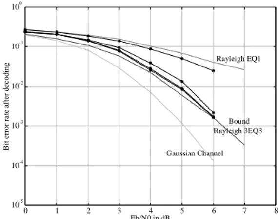
In figure 6 we investigate the performance of the MI-TEQ for 16-QAM over the multiple-output channel 3EQ3. Performance of MI-TEQ is plotted in solid line (4 iterations). After only three iterations, performance of the MI-TEQ reaches the IC bound.
0 1 2 3 4 5 6 7 8 10-5 10-4 10-3 10-2 10-1 100 Eb/N0 in dB
Bit error rate after decoding
Rayleigh EQ1
Bound Rayleigh 3EQ3 Gaussian Channel
Fig. 6. Performance of the MI-TEQ with 16-QAM for three antennas and 3EQ3 Rayleigh channel We would like to emphasize the low complexity of this receiver in comparison with classical MAP receiver. Indeed, using a MAP detector to equalize HT100 channel with 16-QAM modulation requires a trellis with more than 106 states whereas the MI-TEQ needs only linear filtering with a limited number of coefficients to perform equalization.
V.CONCLUSION
This paper describes a low complexity multiple-input receiver for high order modulations and large delay spread channels. After only few iterations, the MI-TEQ removes ISI, collects the energy of the different taps and exploits the coding gain. Presented in this paper with 4-QAM and 16-QAM, the MI-TEQ can be easily extended to higher order modulation without increasing the complexity.
REFERENCES
[1] A. Glavieux, C. Laot and J. Labat, "Turbo-equalization over a frequency selective channel," Symposium on Turbo-Codes, pp. 96-102, Brest, Septembre 1997.
[2] C. Laot et al, "Turbo Equalization : Adaptive Equalization and Channel Decoding Jointly Optimized," IEEE JSAC , VOL. 29, NO. 9, september 2001.
[3] C. Douillard et al., "Iterative Correction of Intersymbol Interference : Turbo-equalization", European Transactions on
Telecommunications, Vol.6, N°5, pp. 507-511, 1995.
[4] C. Berrou and A. Glavieux, " Near Optimum Error Correcting Coding And Decoding : Turbo-codes," IEEE Trans.Comm. Vol. 44, N°10, pp.1262-1271, Oct. 1996.
[5] M. Tuechler et al "Turbo Equalization: principles and new results," submitted to the IEEE Trans. on Com., August, 2000. Preprint, http://www.uiuc.edu/~acsinger/
[6] L.R. Bahl et al., "Optimal Decoding of Linear Codes for Minimizing Symbol Error Rate", IEEE Trans. Info. Theory, Vol IT-20, no. 3, pp. 284-287, March 1974.