HAL Id: hal-03216723
https://hal.archives-ouvertes.fr/hal-03216723
Submitted on 4 May 2021
HAL is a multi-disciplinary open access
archive for the deposit and dissemination of
sci-entific research documents, whether they are
pub-lished or not. The documents may come from
teaching and research institutions in France or
abroad, or from public or private research centers.
L’archive ouverte pluridisciplinaire HAL, est
destinée au dépôt et à la diffusion de documents
scientifiques de niveau recherche, publiés ou non,
émanant des établissements d’enseignement et de
recherche français ou étrangers, des laboratoires
publics ou privés.
The smart grid simulation framework: model-driven
engineering applied to cyber-physical systems
David Oudart, Jérôme Cantenot, Frédéric Boulanger, Sophie Chabridon
To cite this version:
David Oudart, Jérôme Cantenot, Frédéric Boulanger, Sophie Chabridon. The smart grid simulation
framework: model-driven engineering applied to cyber-physical systems. MODELSWARD 2020: 8th
international conference on Model-Driven Engineering and Software Development, Feb 2020, Valletta,
Malta. pp.3-25, �10.1007/978-3-030-67445-8_1�. �hal-03216723�
Model-driven engineering applied to
Cyber-Physical Systems
David Oudart1, J´erˆome Cantenot2, Fr´ed´eric Boulanger3, and
Sophie Chabridon1
1 SAMOVAR, T´el´ecom SudParis, Institut Polytechnique de Paris, France 2
EDF R&D, Palaiseau, France
3 LRI, CNRS, CentraleSup´elec, Universit´e Paris-Saclay, France
Abstract. Smart grids are complex systems for which simulation offers a practical way to evaluate and compare multiple solutions before deploy-ment. However, the simulation of a Smart Grid requires the development of heterogeneous models corresponding to electrical, information process-ing, and telecommunication behaviors. These heterogeneous models must be linked and analyzed together in order to detect the influences on one another and identify emerging behaviors. We apply model-driven engi-neering to such cyber-physical systems combining physical and digital components and propose SGridSF, the Smart Grid Simulation Frame-work, which automates tasks in order to ensure consistency between different simulation models. This framework consists mainly of a domain specific language for modeling a cosimulation unit, called CosiML for Co-simulation Modeling Language, a domain specific language for modeling the functional architecture of a Smart Grid, called SGridML for Smart Grid Modeling Language, and a tool implementing different transforma-tion rules to generate the files and scripts for executing a cosimulatransforma-tion. Finally, we illustrate the use of SGridSF on the real use case of an is-landed grid implementing diesel and renewable sources, battery storage and intelligent control of the production. We show the sequencing of au-tomatic generation tasks that minimizes the effort and the risk of error at each iteration of the process.
Keywords: Cosimulation, FMI, IT, MDE, smart grid, cyber-physical system
1
INTRODUCTION
Tomorrow’s energy systems, or Smart Grids, require the study and devel-opment of safer, controlled components, in order to limit the often costly hardware tests and deployments in this sector of activity. Simulation is recognized as a practical way for verifying and validating the systems before deployment. Our work responds to the problem of finding tools and methods to simulate a Smart Grid, and which allow to remain com-patible with the constraints, especially economic, of the industry. Smart
Grids are complex systems, combining, like all cyber-physical systems, heterogeneous behaviors distributed among several models, themselves developed by persons with different technical profiles and skills. We con-sider cosimulation with the Functional Mockup Interface (FMI)4 stan-dard as the best way to take into account all these models and assess the behavior of a Smart Grid.
We identified two main challenges to be solved. The first challenge con-cerns the heterogeneity of the domains involved. Simulating a Smart Grid requires the ability to model and simulate electrical, information pro-cessing, and telecommunications behaviors and to integrate them within an FMI cosimulator. These behaviors follow different laws of evolution, continuous for the physical components and discrete for the digital com-ponents. One of the current limitations of FMI is its incompatibility with the manipulation of discrete signals, resulting in the absence of compati-ble Telecom simulators. To overcome this limitation, we have previously proposed in [12] a method to allow the exchange of discrete signals be-tween several FMUs. It consists in an encoding component to transform a discrete signal into two time-continuous signals that can be exchanged over FMI, and a decoding component to perform the reverse operation and obtain the discrete-event signal from the FMI discretization of the time-continuous signals.
The second challenge is to ensure the consistency of models produced by persons specialized in different domains when designing a Smart Grid. We rely on model-driven engineering and more specifically on del transformation to maintain the consistency between the design mo-dels of a Smart Grid and simulation momo-dels. We propose SGridSF, the Smart Grid Simulation Framework tooled environment, which automates a number of repetitive tasks in order to ensure consistency between dif-ferent simulation models. This environment consists of a domain specific language for modeling a cosimulation unit, called CosiML for Cosimu-lation Modeling Language, a tool implementing different transformation rules to generate the files and scripts for executing a cosimulation, a spe-cific language for modeling the functional architecture of a Smart Grid, called SGridML for Smart Grid Modeling Language, two specific mod-eling languages, called AllocationML for Allocation Modmod-eling Language and CatalogML for Catalog Modeling Language allowing the definition of a transformation from a model written in SGridML to a model writ-ten in CosiML, and finally a tool implementing the transformation from three models written in SGridML, AllocationML and CatalogML into a model written in CosiML.
In the next section, we discuss existing solutions to the two challenges we mentioned above. Section 3 presents a global overview of the cosi-mulation approach and the integration of our Smart Grid Sicosi-mulation Framework in it. Section 4 and section 5 respectively present how the CosiML and the SGridML languages are build and how to use their as-sociated tools. Section 6 illustrates the approach on a use case. Section 7 presents scenarios to validate our approach.
4
2
STATE OF THE ART
In the electrical energy community, the challenge of simulating smart grids is not new [9, 10, 18]. However, it usually consists in the interaction of two domains via two dynamic models. The problem of the synchro-nization of models and of their consistency is not specifically addressed by these approaches, but is not really challenging when limited to two domains.
For the industrial simulation of complex systems and CPS, it is better to rely on standard technologies, as they address various needs like scalabil-ity, modularity or reusability. The Functional Mockup Interface (FMI) [2] and The High Level Architecture (HLA) [4] are two interoperability ap-proaches allowing the interconnection of several different simulators in an integrated execution.
If both approaches have been declared as standard, FMI benefits from a stronger popularity with more than 80 compatible tools5. Its ability to protect industrial property inside FMUs makes it very attractive for industrial projects and makes collaborative design easier [7]. FMI defines a simulation unit format called Functional Mockup Unit (FMU), which embeds a model and an execution engine along a standard interface to control the execution of the simulation. FMI cosimulations are driven by a master algorithm, which synchronizes the execution of the FMUs and the exchange of data at some communication points.
Because a time-step between two communication points can not be null, FMI is not particularly adapted to reactive systems and discrete-event modeling. Current works already propose FMI extensions, such as zero-size steps [3, 8], or absent values [3] to handle discrete-event signals. Optimized master algorithms [15, 17] can increase the precision of the simulation while still being compliant with the standard, by trying to locate the occurrence of an event using the optional rollback FMI feature (reverting the state of an FMU to a previous communication point), or by optimizing the choice of the time step, which requires FMUs to be exported as white boxes.
The design of complex systems involves several viewpoints from different technical domains, therefore several heterogeneous models developed by different teams are used. In the industry, the interconnection of these models and the consistency links between them are handled using model driven approaches [1,14,19]. These approaches mainly aim at facilitating the realization of the final system, but only few of them include the simulation in the design process [13].
The simulation of Smart Grids requires models dedicated to modeling and design, that describe the system and its architecture at a certain level of abstraction. More abstract models can be automatically derived by model transformations into detailed executable models, thus reducing the risk of inconsistency between models at different levels of abstrac-tion. This automation is particularly beneficial in the case of iterative approaches, every change in the design models being quickly and easily reflected in the derived models.
5
We can distinguish two categories in the existing approaches. The first category relies on system architecture models and derives them into exe-cutable models, such as the code of the software parts of the system. This encompasses the model-driven architecture (MDA6), PSAL [1] or the SGAM Toolbox [16]. The second category aims at validating the models through simulation. They rely on models of the simulation architecture, which makes it possible to keep the dynamic models of the simulation consistent. Examples in this category are model composition approaches (Ptolemy II7, ModHel’X8) or current cosimulation solutions [7]. There-fore, approaches based on system architecture models do not integrate the models of the dynamics of the system, and approaches focused on simulation do not describe the alignment of the simulation models with the system architecture. In our work, we propose to reconnect the two activities of modeling and simulation, and thus link the design models of a Smart Grid to the simulation models of its behaviour.
3
OVERVIEW OF THE SMART GRID
SIMULATION FRAMEWORK
3.1 An Approach Based on Model Refinement
One of the main advantages of using a cosimulation environment is to allow the different experts to develop their own model in autonomy, with a minimal interference and in parallel with the others [7]. The choice of the FMI standard ensures the technological compatibility of each simu-lation unit, or FMU, with the cosimusimu-lation environment, without having to develop a specific connector. However it does not ensure structural compatibility. All FMUs produced by the different teams must provide interoperable data structures, namely each input should match an out-put, in type and meaning.
An example of a cosimulation approach for smart grids [11] identified several steps and actors involved in such a process. The first step is to define all the connections between the simulation models in order to define the interface of the models for each modeling team. But the compliance verification of the models and the creation of the cosimulation artifacts (FMUs, configuration files) are done by hand, which make each iteration time-consuming and error-prone.
The use of a global, architectural model to represent the structural inter-faces of the various simulation units and the coupling constraints between them, allows the use of syntactic tools to automatically check some vali-dation rules. It also creates a unique authoritative artifact to coordinate the work of the various collaborators, and from which more detailed mo-dels can be derived.
Following this approach, we developed a toolchain to automate the ac-tions needed to run a cosimulation starting from a global abstract model.
6 https://www.omg.org/mda/ 7
https://ptolemy.berkeley.edu/
8
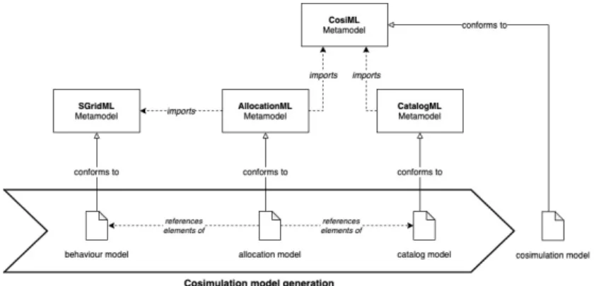
This toolchain relies on a domain specific language (DSL), CosiML, to specify the structural interfaces of the simulation units and the configura-tion of the cosimulaconfigura-tion. In our approach, the cosimulaconfigura-tion model written with CosiML acts as an intermediate, platform-independent model from which executable simulation artifacts can be generated (see section 4). SGridML is a DSL developed to identify and connect the functional behaviors of the Smart Grid together. The different domain experts in-volved in the Smart Grid design are meant to collaborate on the devel-opment of a behavior model with SGridML. Then the behavior model is processed to generate the cosimulation model, according to the map-ping defined in the allocation model and the catalog model, respectively written with AllocationML and CatalogML (see section 5). Figure 1 illus-trates the generation of the cosimulation model and the relations between the four DSL involved in the model transformation.
Our choice to develop our own languages for this purpose, instead of choosing an existing one, such as UML, comes from various reasons :
– in an industrial context, general-purpose languages like UML are not well mastered outside the computer science field,
– such languages contain many concepts, but we only needed a few of them,
– in our approach, adapting UML to model specific concepts would lead to refining generic concepts through profiles.
It appeared more efficient to define only what we needed than to restrict and specialize UML to fit our needs.
Fig. 1. Cosimulation model generation, with dependency links
Smart Grid Simulation Framework is the name we give to the tool suite composed by the four languages presented and their associated tools. It is by construction supporting the phases and steps of a cosimulation approach:
1. Phase 1 constitutes the step sequence resulting in the complete mo-del of the Smart Grid. First step consists in the definition of the system to model. Then, the responsability to produce the simula-tion models is split between the different expert teams involved.
The third step specify the interfaces of each model and the interac-tions between them. Finally, the simulation models can be developed according to these specifications.
2. Phase 2 aims to configure the cosimulation unit to be executable. First the simulation models have to be available in the executable cosimulation format, FMU in our case. Then the simulation param-eters and coupling constraints are implemented in the master of co-simulation.
3. Phase 3 consists in the execution and analysis of the cosimulation results. First the results should be assessed to determine if there has been any design mistake compared to the initial expectations (sim-ulation or functional errors). Once the results are validated, further decisions can be make according to the efficiency of the solution. Either the design of the solution is accepted, or it need iterative improvement.
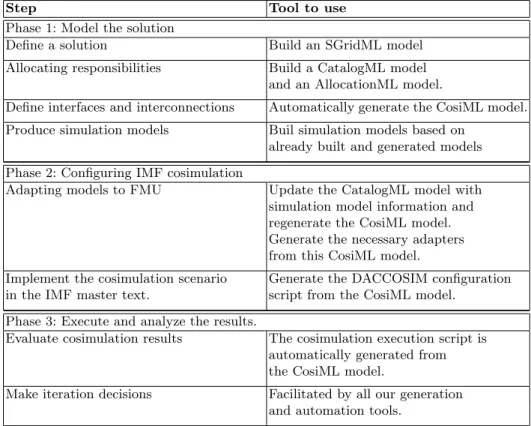
Table 1 presents the correspondence between the phases of the cosimu-lation approach and the tools of the Smart Grid Simucosimu-lation Framework.
Step Tool to use
Phase 1: Model the solution
Define a solution Build an SGridML model
Allocating responsibilities Build a CatalogML model and an AllocationML model.
Define interfaces and interconnections Automatically generate the CosiML model. Produce simulation models Buil simulation models based on
already built and generated models Phase 2: Configuring IMF cosimulation
Adapting models to FMU Update the CatalogML model with simulation model information and regenerate the CosiML model. Generate the necessary adapters from this CosiML model. Implement the cosimulation scenario
in the IMF master text.
Generate the DACCOSIM configuration script from the CosiML model.
Phase 3: Execute and analyze the results.
Evaluate cosimulation results The cosimulation execution script is automatically generated from the CosiML model.
Make iteration decisions Facilitated by all our generation and automation tools.
This remains a qualitative and human work. Nevertheless, the imple-mentation of iteration decisions is facilitated by all our generation and automation tools.
3.2 Download
Our toolchain is shared on a github repository at: https://github.com/davidoudart-pro/SGridSF
The sources of the CosiML language and generation plugins are available, as well as the necessary files to replay the cosimulation of the use case presented in the next section of the article.
4
MODELING AND EXECUTION
OF A COSIMULATION SCENARIO
4.1 CosiML, a DSL for Cosimulation
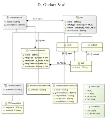
We implemented CosiML inside the Eclipse Modeling Framework (EMF) using the Ecore metamodeling language. Figure 2 shows the metamodel of CosiML. The classical elements of every cosimulation are represented:
CosimulationModel is the root element of the model, it stores the parameters of the cosimulation (start time, stop time, time step, etc.) and contains all the simulation units and their interconnec-tions.
SimulationUnit represents a simulation unit involved in the cosi-mulation. It contains the Port elements representing the structural interface of the unit.
Input & Output (Port) represents a port of the simulation unit. It has a type, an optional default value and a variability, which is the name used by FMI to characterize the discrete or continuous nature of signals.
Link represents a connection between an output and an input port. A model can be checked to verify that any two connected ports have the same variability, and that they are not contained in the same simulation unit.
Several kinds of SimulationUnits can be instantiated in a cosimula-tion model, depending on the source format of the simulacosimula-tion unit provided:
ProvidedSimulationUnit is a simulation unit which is completely provided by the user. Such a simulation unit is directly usable in the cosimulation without further action. In our case of FMI cosimu-lation, a ProvidedSimulationUnit is provided as an FMU resource and we only have to know the path to the artifact.
Fig. 2. CosiML metamodel
GeneratedSimulationUnit is a simulation unit which will be generated by the toolchain from a domain model. The attribute modelPath stores the path to the domain model. The format of the model and the generator to use for the generation of the simulation unit are specific to the tool attribute’s value. The tool is what is used to build the model, for instance a Java or C++ compiler, or a more complex modeling tool such as OMNeT for communication networks. The generator is part of our toolchain, and will generate the corresponding FMU, which includes the generation of adapters for discrete event signals. The generator relies on naming conven-tions to access the elements of the model and adapt them to the structure of the FMU. For instance, a Java with a continuous input signal named X should implement a setX(double value) method. In order to refer to the model in the generated FMU, the genera-tor uses two generic attributes: importText defines how to import the model inside the adapter, and usageText tells how to use the model. Finally, the attribute dependencies stores the list of all the resource paths required by the model (libraries, data files, binaries) that should be packaged inside the generated simulation unit. Our goal is to stay generic enough to avoid metamodel modifications when we want to support a new tool and add a new generator to the toolchain. For instance, a Java model-based generator would
require:
importText = import package.Classname; and
usageText = Classname,
whereas a C++ model-based generator would require: importText = #include "filename.h"
and
usageText = ObjectName.
DataSourceUnit a simulation unit generated by the toolchain from a data file. It only has output ports and will be used as an independent source of timed data. The attribute dataPath stores the path to the data file. We are considering that future versions of CosiML and the toolchain may support several format, but for now we only support CSV files to be used as Scenario units. CSVSourceUnit a particular Scenario element which refers to a CSV data file. Attributes separator and decimal define the char-acters used respectively as separator and decimal marker for the CSV content.
4.2 Generation Tools for FMI Cosimulation
We chose the DACCOSIM NG9 software to execute our FMI
cosi-mulation. It implements a master algorithm that is fully compliant with the standard, with advanced discontinuity detection features, and intelligent time step strategies [15]. More importantly, it pro-vides a scripting language allowing the automation of the build and execution of cosimulations. Finally it is designed for distributed ex-ecutions, which is very useful for industrial use cases potentially involving a large number of FMUs [6].
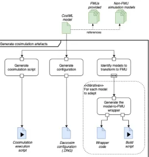
We developed an Acceleo plugin to generate all the files needed to build the FMI cosimulation from the CosiML model. Figure 3 shows the generation process of these files from a CosiML model. The generators are configured with property files, used to specify platform dependent information, such as library and tool paths. Whereas CosiML is meant to be fully generated according to the steps defined in Table 1, it is an independent tool which can be adapted to one’s own simulation methodology. Because our CosiML metamodel is defined with EMF Ecore, one can use the Sample Reflective Ecore Model Editor to instantiate a CosiML model and serialize it in the XMI format, in order to use it with the following associated tools to generate an executable cosimulation unit:
1. OMNeT generator: generates all the files needed to build an FMU from an OMNeT model. It is applied to the Generated-SimulationUnit instances with the tool property set to ”java”.
9
It generates a JSON configuration file, compatible with our own C++ plugin of the OMNeT simulation core. This plugin allows the FMU export of an OMNeT model. It implements the encod-ing and decodencod-ing components presented in our previous work to allow discrete signal exchanges over FMI. The generator also produces a script to build the corresponding FMU.
2. Java-tool generator: generates all the files needed to build an FMU from a Java model. It is applied to the GeneratedSim-ulationUnit instances with the tool property set to ”java”. It generates a Java file defining a class adapting the user model to the JavaFMI library10, along with a MANIFEST.MF file defin-ing the proper classpath. It also generates a script to build the corresponding FMU.
3. CSV scenario generator: generates the files needed to build an FMU from a CSV file. It is applied to the CSVScenario instances. It generates a Java file defining a class loading the CSV file, and implementing the JavaFMI library, along with the MANIFEST.MF file and the building script, just as with the Java-tool generator.
4. Cosimulation scripts generator: generates the DACCOSIM cosimulation model in its specific scripting language DNG. It also generates an execution script, which automates the build of all the FMU not yet generated, and the launch of the DAC-COSIM simulation.
CosiML allows the distinction between discrete and continuous data exchanges, so that the provided generators can automatically implement our discrete-continuous encoding and decoding compo-nents [12] in the generated wrappers, and adapt the FMU inputs and outputs accordingly (each CosiML Port with a discrete vari-ability causes the creation of two FMI ports). Our CosiML toolchain is meant to be extended with other generators to support more do-main specific tools and to be used for cyber-physical systems other than smart grids. The next section presents the SGridML, Allo-cationML and CatalogML languages, and how they are used to produce the CosiML cosimulation model.
5
FUNCTIONAL ARCHITECTURE
FOR SMART GRID SIMULATION
5.1 SGridML
As for CosiML, we have a metamodel of SGridML expressed in the Ecore language. This language makes it possible to represent two
10
bitbucket.org/siani/javafmi/, a set of component to work with FMI. It especially provides a builder component generating an FMU from Java code
Fig. 3. Generation process of the cosimulation artifacts, from a CosiML model
types of behavior: functional behaviors (for creating and modify-ing data), and data transmission behaviors. This manipulated data represents information regardless of its form: physical state, digital information, or intangible facts.
Figure 4 shows the complete SGridML metamodel, whose elements are described below :
BehaviorModel: Root element, used for model navigation pur-poses only. It contains a list of the functional behaviors of the system (function), the existing connections between these functions (connection), and the possible transmission behav-iors of these connections (transmission).
SimulationBehavior: Element representing an instance of an el-ementary simulation behavior, named by its attribute name. Function: Element derived from SimulationBehavior,
represent-ing a functional behavior of the system simulation. It contains an input interface (list input), and an output interface (list output). These interfaces are described in a static way, and thus represent all possible data exchanges in and out of this behavior during the system simulation.
Output & Input: These elements represent a data exchange point, part of the interface of a functional behavior. An Input is an entry point for a data, allowing us to provide the behavior that contains it with the data necessary to its realization. Similarly, an Output is an output point, allowing us to share a data
pro-Fig. 4. Ecore metamodel of SGridML
duced by the behavior that contains it, with the other func-tional behaviors of the model. Each element has a name, the type of data that can be exchanged, and a boolean, dataType, indicating whether the data is continuous or discrete in nature. Connection: Element representing a connection between an out-put interface point of a functional behavior of the model tribute output), and an input interface point of another (at-tribute input). This indicates that a signal bearing the evolu-tion of a data will be exchanged during the simulaevolu-tion of the system, between the two connected behaviors. The transmis-sion behavior of this connection can be specified by its optional attribute transmission. If this attribute is not specified, the transmission is considered instantaneous and perfect (without value modification).
Transmission: Element derived from SimulationBehavior, rep-resenting a transmission behavior of the system simulation. Transmitted data may be altered, i.e. delayed, deleted or mod-ified by this behavior. However, unlike a functional behavior, a transmission behavior does not have an explicit input or output
interface. We explain the nature of this transmission behavior with the isContinuous attribute.
DataType: A list representing the different types of data possible. We can have a relative integer (INTEGER), a real number (REAL), a string (STRING) or a boolean value (BOOLEAN).
We define an instantiated behavior SimulationBehavior as ele-mentary by the fact that we do not want to break it down into sub-behaviors, often because they are too strongly coupled and the definition of their interconnections too complex.
By connecting these behavioral instances together, we obtain a mo-del of all the possible data exchanges between the components that will implement these instances. In the way we use this lan-guage, a SimulationBehavior can be allocated to a simulation unit in an AllocationML model. A constraint of this use is that a SimulationBehavior must be able to be fully implemented in a sin-gle simulation unit, otherwise this element must be re-decomposed. Eclipse EMF provides an editor for creating or modifying XMI for-mat models that conform to an Ecore metamodel: the Sample Re-flective Ecore Model Editor. We use it to develop models in CosiML, or to develop our own concrete syntax.
5.2 AllocationML and CatalogML:
Two DSLs to Define the Transformation
The AllocationML model allows us to map a simulation represented by an SGridML model to the architecture of a cosimulation repre-sented by a CosiML model. Indeed, in order to be able to cosimulate the system modeled with SGridML, the simulation units must re-spect a minimum interface, and some interconnections must appear in the cosimulation scenario.
These consistency links can be exploited in several ways, for exam-ple, by developing a verification and error detection tool between an SGridML model and a CosiML model. A second option, which is the one we choose to develop, is to generate the necessary elements in a CosiML model to be consistent with a given SGridML model. The generator creates the Ports of the SimulationUnits, and the Links between them in the CosiML model. Rather than provid-ing this generator with an incomplete CosiML model to fill it, we prefer to model the elements that cannot be generated automati-cally (CosimulationModel and the SimulationUnits) in reusable component libraries, and to generate the entire cosimulation model. CatalogML is a DSL developed for this purpose. It is used to define a catalog of simulation units (SimulationUnit) with an undefined or incomplete interface (Port).
Figures 5 and 6 show the complete AllocationML and CatalogML metamodels, respectively.
Fig. 5. AllocationML metamodel
Fig. 6. CatalogML metamodel
AllocationModel: Root element of the allocation model, it con-tains a list of mappings (mapping). It also concon-tains the simu-lation parameters, which are the start date (starttime), end date (stoptime) and the duration of the time step between the cosimulation communication points (stepsize).
Mapping: Element representing an allocation link between a be-havior instance (simulationbebe-havior) and a simulation unit (simulationunit).
We add a generic attribute called parameters, in order to al-low the user to parameterize how a behavior instance is linked to a simulation unit (for example to detail how to link the in-put and outin-put data of the behavior with the model included in the simulation unit). It is up to the user wishing to bring compatibility with a new tool to define how this field should be analyzed (parsing operation), if he needs it.
The SimulationBehavior and SimulationUnit elements are not part of AllocationML. They are imported from the Ecore SGridML and CosiML metamodels.
Catalog: Root element of the model, used as a container for a list of simulation units (simulationunit).
5.3 Generation of a CosiML cosimulation model
The generation of a CosiML cosimulation model requires an SGridML behavior model, a CatalogML catalog model and an AllocationML allocation model. Figure 1 illustrates the dependencies between these different models.
Some transformation rules are simple: the simulation units of the catalog model linked by the allocation model are copied into the cosimulation model, as well as the configuration of the selected cosi-mulation. But the rules for generating ports and links are more com-plex because they require many model paths and special genera-tion condigenera-tions. The principle is as follows. From a SGridML::Con-nection element of the behavior model:
1. We call In the corresponding SGridML::Input and Out the corresponding SGridML::Output. We call Finand Fout the
re-spective SGridML::Function containers of In and Out. If the connection has a SGridML::Transmission, we call it T . 2. These grid lines can be allocated to simulation units. Thus,
each connection can be between 0 and three simulation units. We call them A, B and C. We’re considering a fourth pseudo-simulation unit to mean that a Simulation Behavior hasn’t been allocated.
3. Depending on how these three SimulationBehaviors can be allocated on these four SimulationUnits, between zero and two Ports and between zero and two Links are generated in the CosiML model.
When T is “allocated” on ∅, we consider the connection to be an instantaneous transmission. But we decide to prohibit cases where Fin or Fout are not allocated (the connection is ignored).
For each SGridML::Connection element, Table 2 shows the ele-ments to be generated in the CosiML output model depending on the allocation of Fin, Fout and T to A, B, C and ∅. We use the
following notation for the ports and links to be generated:
– ∈ A means that the observed grid behavior is allocated to A and ∈ ∅ means it is not allocated. We write ∈ ∅ for T in cases where T is not allocated, or does not exist (the connection has no SGridML::Transmission).
– −−→Out and ←In represent respectively a CosiML::Output and a− CosiML::Input transformed from In and Out (respectively). −−−−−−→
Out − In represents a CosiML::Output transformed from the (In, Out) pair.
– A → B represents a CosiML::Link between the generated out-put ports of A and the generated inout-put ports of B.
– We do not represent the additional synchronization CosiML:Port generated in the case of a discrete signal, because it follows the same rules of creation and connection as the information CosiML::Port.
Input elements Generated elements
Units linked to Connection
SimulationBehavior Port Link
FOutFIn T A B C A ∈ A ∈ A ∈ A - - - -A, ∅ ∈ A ∈ A ∈ ∅ - - - -A, B ∈ A ∈ B ∈ B −−→Out ←In− - A → B ∈ A ∈ B ∈ A −−→Out ←In− - A → B ∈ A ∈ A ∈ B −−→Out←− In −−−−−−→ Out − In ←−−−−−− Out − In - A → B → A A, B, ∅ ∈ A ∈ B ∈ ∅ −−→Out ←In− - A → B A, B, C ∈ A ∈ B ∈ C −−→Out ←In− −−−−−−→Out − In←−−−−−− Out − In A → C → B
Table 2. Transforming a Connection element to Port and Link elements
6
USE-CASE COSIMULATION
6.1 The Use-Case of an Islanded Smart Grid
We chose a real use case from the French power utility to illus-trate our contribution, and validate our toolchain. The system is an island with a power grid that is independent from the mainland grid, with its own production equipments. A diesel power plant is the main energy producer, and is complemented by a photovoltaic farm. The main issue in the configuration is that the renewable energy supply is intermittent. Indeed, as the photovoltaic source relies on sunlight and needs a clear sky for its production, it makes it as variable and unpredictable as the weather. In order to bal-ance the production with the consumption, it has to be sometimes prevented from producing as much as it could, which causes eco-nomic loss and carbon footprint degradation. Therefore, a chosen solution is to add a battery storage to damp the variability of the production, with the purpose of minimizing the limitations of the photovoltaic farm. It could even allow the operator to shut down
the diesel plant for some period and rely only on the battery and photovoltaic production.
To maximize the efficiency of the system, we need an Energy Man-agement System (EMS) coupled with a Supervisory Control And Data Acquisition (SCADA) in order to implement an intelligent control of the production. The EMS monitors the state of the power grid (value of the voltage at various control points, state of switches), and drives some of its equipments (giving voltage set-points, limiting the injection of power by a source) through the SCADA. The EMS can collect other information such as weather and consumption forecasts from external information systems, as well as user preferences, in order to optimize the operation of the grid.
Before telling how the EMS controls the equipments on the grid, we have to explain how the power flow is established on a power grid. Knowing the power needed by the consumers, we can set power production set-points to the various sources of the grid in order to balance the consumption. However, losses on transmission lines can never be known, so we need at least one equipment that is not power constrained, and capable of producing the missing power or of absorbing the unpredictable excess. This equipment is generally the one having the biggest generator. In our case it is the diesel plant when it is connected to the grid, and the battery and its converter when it is not.
The EMS sends control signals to the various equipment of the grid: – photovoltaic farm: the EMS decides if the production needs to
be limited and how much;
– battery: there are two cases for this equipment. When the diesel plant is coupled to the grid and balances the power on the grid, the EMS controls the power absorbed or injected by the battery. When the diesel plant is shut down, the EMS does not control the battery and lets its power converter balance the power on the grid.
– diesel plant : the EMS decides if it is coupled to the grid (and produces power) or not. When it is coupled to the grid, it cannot produce less than a minimum power, so it can happen that the photovoltaic farm has its production limited. To avoid it, the diesel is turned off when the battery and the photovoltaic production are able to cover the consumption needs.
Because of all the different modes in which the grid can be, depend-ing on the weather, on the management of the charge of the battery and on the variability of the consumption, simulation is very useful to test and validate a design of the solution, before any deployment on the field and expensive investments.
6.2 Behavior Model with SGridML
The simulation of the islanded smart grid is a good example of a cyber-physical system involving several knowledge fields, and seve-ral teams with different modeling tools. The first step to achieve is the development of the behavior model with SGridML. A proposi-tion for the funcproposi-tional behaviors involved in the Smart Grid under design is illustrated in Figure 7. As shown, all interactions com-ing to and from the ControlsComputcom-ing behavior are discrete, and realised by the TelecomTransmission behavior. All other interac-tions are continuous and realized by the PhysicalTransmission behavior.
Fig. 7. Behavior model of the islanded power grid to simulate
6.3 Allocation, Catalog & Simulation Models
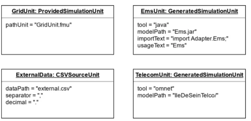
Once the functional and transmission behaviors have been identi-fied in the behavior model, they have to be allocated to a specific simulation unit. We decided to use four simulation units, that we describe in the catalog model with CatalogML, as illustrated in Figure 8.
Fig. 8. Simulation units decribed in the catalog model
The first simulation unit, GridUnit, models the electric behavior. As such, the GridStateComputing, the EnergyStoring, and the PVPowerComputing functional behaviors, as well as the Physical-Transmission behavior, are allocated to this GridUnit in the allo-cation model written with Alloallo-cationML. GridUnit evaluates the electrical power state of the grid according to production and con-sumption constraints. We are using Modelica11 with the Dymola
software to model the grid power flow because they are well-known tools among electrical engineers, and they fully support the FMI standard and the export to FMU [5]. GridUnit is therefore an in-stance of ProvidedSimulationUnit.
The second simulation unit, EmsUnit, models the behavior of the EMS. Only the ControlsComputing functional behavior is allo-cated to it in the allocation model. There is no conventional tool supporting the modeling of reactive systems and also handling FMI. Complex algorithms are usually modeled with textual procedural languages such as C or Java. There are tools supporting the ex-port of such models toward FMU, but they require additional ef-forts and specific code refactoring and writing. Our Smart Grid Simulation Framework supports the automatic transformation of a Java model into an FMU, with the generation of a wrapper code implementing the JavaFMI Framework library, and the use of the JavaFMI builder tool. EmsUnit is therefore an instance of GeneratedSimulationUnit. We developed a first, simple Java al-gorithm of the EMS which takes the current state of the grid as input and does not use forecasts. It computes controls every 15 minutes, but continuously monitors the current state of the grid equipments in case emergency controls are required. Figure 9 shows an activity diagram, illustrating this process.
11
https://www.modelica.org/, component-oriented modeling language based on equa-tions set declaration
Fig. 9. EMS monitoring process, with periodic and emergency controls
The third simulation unit, ExternalDataUnit models the inde-pendant, external input data used in our use case cosimulation. The Lightning and Consuming behaviors are allocated to this unit in the allocation model. We chose to provide these timed data in a CSV file, transformed to FMU format thanks to our CSV source generator. Therefore, ExternalDataUnit is an instance of CSVSourceUnit in the catalog model.
Finally, the fourth simulation unit, TelecomUnit, models the tele-com transmission behavior. Teletele-comTransmission is allocated to this unit in the allocation model. We are using the OMNeT mod-eling and simulation software to develop this simulation model. Hence, TelecomUnit is an instance of GeneratedSimulationUnit, meant to be use with our OMNeT generator to produce the required FMU.
6.4 Simulation Models and Cosimulation Model
The development of a behavior model with SGridML, a catalog model with CatalogML and an allocation model with AllocationML allows us to automatically generate the cosimulation model. This generated model instanciates the same simulation unit as those described in the catalog model, as well as their structural interfaces and coupling constraints.
Through the generation of the cosimulation model, we are now able to generate all the artifacts and scripts to build an executable cosi-mulation unit. Indeed, all sicosi-mulation models can be automatically converted to the FMU format, and a configuration file as well as a global execution script are generated by the Smart Grid Simulation Framework.
6.5 Simulation and Decisions
The use case presents two main concerns: 1) how to optimize the characteristics of the battery in order to implement an efficient management of the production and keep investment as low as pos-sible? And 2) how to test the efficiency of the chosen EMS algo-rithm?
From the CosiML model, the toolchain generates the necessary wrapper files to build the EmsFmu and CurvesFmu FMUs, as well as the DACCOSIM model of the cosimulation. In addition, a script is generated to create automatically the missing FMUs, and to launch the DACCOSIM cosimulation.
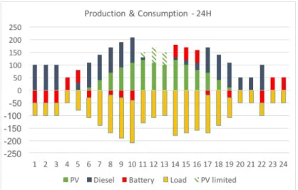
In our case, the cosimulation evaluates the behavior of the grid on a full day (24 hours). Figure 10 shows the average and cumulated per-hour production (over the x-axis) and consumption (below the x-axis) of each equipment on the day, for particular load and pho-tovoltaic maximal production curves (and initial conditions).
Fig. 10. Consumption and production of electricity over a full day
The energy balance has been ensured all day (no black-outs) mean-ing our design solution is effective on this particular scenario. How-ever, between 11am and 2pm, the photovoltaic production has been limited (see hatched bars). Looking at the results (not shown in the figure), we see that the charge of the battery was already maximal and could not absorb the extra production. There is consequently a potential for optimizing our solution. Increasing the capacity of the battery, or improving the algorithm of the EMS are two possi-ble iterations. Once the models are updated, the execution of the
toolchain automatically updates the simulation artifacts and exe-cutes the cosimulation again.
7
OBSERVATIONS
The key motivation behind our work is to reduce the cost of iter-ations in the design of systems by automating the cosimulation of the models using a model-driven approach. To be useful in an in-dustrial context, we need to fulfill the following requirements: each iterative step of the process must provide a quick feedback; the up-front modeling cost must be recovered in the following phases of analysis, maintenance, etc.; business experts must concentrate on their core skills.
We presented in this paper a toolchain based on a cosimulation DSL to reference simulation models and characterize some coupling cons-traints between them. The various generators allow the generation of simulation units and deployment scripts from this cosimulation model. Hence, this automated process provides the possibility to make changes to the cosimulation scenario with minimal efforts. We illustrate this through the following industrial scenarios. In a first scenario, a functional architect has to compare components from various vendors, for example to find the best EMS solution (EMSGrid in our previous use case). To guarantee the correct inte-gration of the simulation model provided by the vendor, the tender documents include requirements deduced from the CosiML model. The selection of the right component is simplified because:
– Using the tool chain, the architect can quickly build a test en-vironment, by providing input data inside a CSV file, automat-ically generating a new FMU and a cosimulation model, then testing multiple configurations easily.
– To select the components to be used in the cosimulation, only the pathFMU attribute of the ProvidedSimulationUnit must be modified and the new cosimulation set up can be generated. In a second scenario, we want to involve electrotechnical engineers to build a load flow model of the power grid (GridFMI in our previ-ous use case). This is possible without an intensive training because they can use their own specific tools to build the simulation model (Dymola, PowerFactory, etc.), and there are only few basic concepts (input, output, discrete or continuous variability) to be explained in order to build the CosiML model. Once they develop a model con-forming to the CosiML metamodel, they can then use an iterative approach to improve the model without involving other collabora-tors, thanks to our toolchain, which automatically integrates their work to the cosimulation platform.
Finally, in a third scenario, we consider the case of a modification of one simulation model inducing a modification of the CosiML
model, and especially among the coupling constraints between mo-dels (e.g. adding or renaming several ports). Firstly, the validation rules of our toolchain guarantee the consistency of the CosiML mo-del. Secondly, the automated execution process of the cosimulation will raise errors until each impacted simulation model makes the necessary adjustments. Thirdly and finally, the implementation of the adjustments might be partially done by the generators of the toolchain.
8
CONCLUSION
By automating some verifications and the generation of cosimula-tion artifacts, model driven approaches allow shorter, less costly and less error prone iterations on a solution design. Our toolchain relies on an abstract CosiML model of the system to check the con-sistency of the different simulation units, to generate adapters for discrete event signals that cannot be used as is in an FMI simula-tion, and to generate FMUs from models developed with different tools. It uses the FMI standard and benefits from its many advan-tages regarding CPS simulation in the industry. It can also integrate FMUs exported by some modeling tools in the cosimulation, allow-ing models from different system domains to be developed with the relevant tools, by experimented teams, while protecting industrial property inside FMUs.
We developed the SGridML language to allow several people from various domains to collaborate on an abstract analysis model of the Smart Grid design. AllocationML and CatalogML allow the distri-bution of the behavior of the system among different simulation models, whose interfaces and coupling constraints are directly val-idated by syntaxic rules. In addition, the transformation between SGridML and CosiML ensures the creation of simulation units con-sistent with the functional design of the system under study. The Smart Grid Simulation Framework has been used on a real industrial case, which involves both continuous and discrete signal exchanges. The included modeling languages and tools have been designed to be used independently, or to support new modeling tools and generators. The modular nature of the different trans-formations also helps to adapt the generated artifacts to different versions of FMI. For instance, the support for a more precise de-tection of discontinuities in FMI v2.1 may lead to a new adapter for discrete event signals, while keeping the current one for cosimu-lations using older versions of FMI.
References
1. Andr´en, F., Strasser, T., Kastner, W.: Engineering Smart Grids: Applying Model-Driven Development from Use Case Design to Deployment. Energies 10(3), 374 (Mar 2017). https://doi.org/10.3390/en10030374
2. Blochwitz, T., Otter, M., Arnold, M., Bausch, C., Elmqvist, H., et al.: The functional mockup interface for tool independent ex-change of simulation models. In: Proceedings of the 8th International Modelica Conference. pp. 105–114 (2011)
3. Cremona, F., Lohstroh, M., Broman, D., Lee, E.A., Masin, M., Tri-pakis, S.: Hybrid co-simulation: it’s about time. Software and System Modeling 18(3), 1655–1679 (2019). https://doi.org/10.1007/s10270-017-0633-6, https://doi.org/10.1007/s10270-017-0633-6 4. Dahmann, J.S., Morse, K.L.: High Level Architecture for
simulation: An update. In: Proceedings. 2nd International Workshop on Distributed Interactive Simulation and Real-Time Applications (Cat. No.98EX191). pp. 32–40 (Jul 1998). https://doi.org/10.1109/DISRTA.1998.694563
5. Elsheikh, A., Awais, M.U., Widl, E., Palensky, P.: Modelica-enabled rapid prototyping of cyber-physical energy systems via the func-tional mockup interface. In: Workshop on Modeling and Simulation of Cyber-Physical Energy Systems (MSCPES). pp. 1–6. IEEE (May 2013). https://doi.org/10.1109/MSCPES.2013.6623315
6. ´Evora G´omez, J., Hern´andez Cabrera, J.J., Tavella, J.P., Vialle, S., Kremers, E., Frayssinet, L.: Daccosim NG: Co-simulation made sim-pler and faster. In: The 13th International Modelica Conference. pp. 785–794 (Feb 2019). https://doi.org/10.3384/ecp19157785
7. Gomes, C., Thule, C., Larsen, P.G., Vangheluwe, H.: Co-Simulation: A Survey. ACM Computing Surveys 51(3), 49:1–49:33 (2018) 8. Guermazi, S., Tatibouet, J., Cuccuru, A., Dhouib, S., G´erard, S.,
Seidewitz, E.: Executable modeling with fUML and alf in papyrus: Tooling and experiments. In: EXE@MoDELS (2015)
9. Li, W., Monti, A., Luo, M., Dougal, R.A.: VPNET: A co-simulation framework for analyzing communication channel effects on power systems. In: 2011 IEEE Electric Ship Technologies Symposium. pp. 143–149 (2011)
10. Nutaro, J.: Designing power system simulators for the smart grid: Combining controls, communications, and electro-mechanical dy-namics. In: 2011 IEEE Power and Energy Society General Meeting. pp. 1–5 (Jul 2011). https://doi.org/10.1109/PES.2011.6039456 11. Oudart, D., Cantenot, J., Boulanger, F., Chabridon, S.:
An Approach to Design Smart Grids and Their IT Sys-tem by Cosimulation:. In: MODELSWARD 19. pp. 370–377. SCITEPRESS - Science and Technology Publications (2019). https://doi.org/10.5220/0007407003700377
12. Oudart, D., Cantenot, J., Boulanger, F., Chabridon, S.: A mo-del based toolchain for the cosimulation of cyber-physical sys-tems with fmi. In: Proceedings of the 8th International Con-ference on Model-Driven Engineering and Software Development
- Volume 1: MODELSWARD. pp. 15–25. INSTICC, SciTePress (2020). https://doi.org/10.5220/0008875400150025, https://www. scitepress.org/PublicationsDetail.aspx?ID=uwfM1k2FY4Y= 13. Paris, T., Ciarletta, L., Chevrier, V.: Designing co-simulation with
multi-agent tools: a case study with NetLogo. In: Francesco Belar-dinelli, E.A. (ed.) 15th European Conference on Multi-Agent Sys-tems (EUMAS 2017). Multi-Agent SysSys-tems and Agreement Tech-nologies, vol. 10767, pp. 253–267. Springer, ´Evry, France (Dec 2017). https://doi.org/10.1007/978-3-030-01713-2 18, https://hal. archives-ouvertes.fr/hal-01687101
14. Suri, K., Cuccuru, A., Cadavid, J., Gerard, S., Gaaloul, W., Tata, S.: Model-based Development of Modular Complex Systems for Ac-complishing System Integration for Industry 4.0. In: Proceedings of the 5th International Conference on Model-Driven Engineering and Software Development - Volume 1: MODELSWARD,. pp. 487–495. ScitePress (2017). https://doi.org/10.5220/0006210504870495 15. Tavella, J.P., Caujolle, M., Vialle, S., al.: Toward an Accurate
and Fast Hybrid Multi-Simulation with the FMI-CS Standard. In: Emerging Technologies and Factory Automation (ETFA-2016). Berlin, Germany (Sep 2016)
16. Uslar, M., Rohjans, S., Neureiter, C., Pr¨ostl Andr´en, F., Velasquez, J., Steinbrink, C., Efthymiou, V., Migliavacca, G., Horsmanheimo, S., Brunner, H., Strasser, T.: Applying the Smart Grid Architecture Model for Designing and Validating System-of-Systems in the Power and Energy Domain: A European Perspective. Energies 12(2), 258 (Jan 2019). https://doi.org/10.3390/en12020258
17. Van Acker, B., Denil, J., Vangheluwe, H., De Meulenaere, P.: Gene-ration of an optimised master algorithm for fmi co-simulation. In: DEVS Integrative M&S Symposium. DEVS ’15, Society for Computer Simulation International (2015), http://dl.acm.org/ citation.cfm?id=2872965.2872993
18. Yang, C.H., Zhabelova, G., Yang, C.W., Vyatkin, V.: Cosimula-tion Environment for Event-Driven Distributed Controls of Smart Grid. IEEE Trans. Industrial Informatics 9(3), 1423–1435 (2013). https://doi.org/10.1109/TII.2013.2256791
19. Zhao, H., Apvrille, L., Mallet, F.: Multi-View Design for Cyber-Physical Systems. In: PhD Symposium at 13th International Con-ference on ICT in Education, Research, and Industrial Applica-tions. pp. 22–28. Kiev, Ukraine (May 2017), https://hal.inria. fr/hal-01669918