HAL Id: tel-01127277
https://tel.archives-ouvertes.fr/tel-01127277
Submitted on 7 Mar 2015
HAL is a multi-disciplinary open access
archive for the deposit and dissemination of sci-entific research documents, whether they are pub-lished or not. The documents may come from teaching and research institutions in France or abroad, or from public or private research centers.
L’archive ouverte pluridisciplinaire HAL, est destinée au dépôt et à la diffusion de documents scientifiques de niveau recherche, publiés ou non, émanant des établissements d’enseignement et de recherche français ou étrangers, des laboratoires publics ou privés.
Carlos Alberto Gonzalez Perez
To cite this version:
Carlos Alberto Gonzalez Perez. Pragmatic model verification. Software Engineering [cs.SE]. Ecole des Mines de Nantes, 2014. English. �NNT : 2014EMNA0189�. �tel-01127277�
Carlos A. G
ONZÁLEZ
Mémoire présenté en vue de l’obtention du
grade de Docteur de l’École nationale supérieure des mines de Nantes
sous le label de l’Université de Nantes Angers Le Mans Discipline : Informatique et applications
Laboratoire : Laboratoire d’informatique de Nantes-Atlantique (LINA) Soutenue le 9 Octobre 2014
École doctorale : 503 (STIM) Thèse n° : 2014 EMNA 0189
Pragmatic Model Verification
JURY
Rapporteurs : M. Antoine BEUGNARD, Professeur, Telecom Bretagne
M. Martin GOGOLLA, Professeur, Universität Bremen
Examinateur : MmeEsther GUERRA, Maître de conférences, Universidad Autónoma de Madrid
The completion of this thesis would have not been possible without the help and support of many individuals. These few lines are just an expression of my gratitude to all of them.
I would like to express my most special thanks and gratitude to my thesis ad-visor, Jordi Cabot, for all the support given throughout these years. Every time I got stuck, his advice helped me to move further. Every time I made a mistake, he offered me valuable and constructive feedback. And more importantly, his door was always opened for me, every time I needed to discuss anything. Without his help, this thesis would have not been possible.
I am also grateful to Robert Clarisó and Fabian Büttner for their help and coop-eration on the development of some of the ideas presented in this thesis.
My thanks also go to the members of the jury, for finding the time to review my work, and for the valuable feedback provided.
Thanks also to the members of the AtlanMod research team for creating such a loving working environment, and specially to Hugo Brunelière, for taking the time to review the French contents of this thesis.
Finally, thanks of course to my family. Their support is always there.
I
Introduction and Basic Concepts
13
1 Introduction 15
1.1 Motivation . . . 15
1.2 Objectives and Contributions of this Thesis . . . 17
1.3 Outline of the Thesis . . . 17
1.4 List of Publications . . . 19
2 Basic Concepts 21 2.1 Model-Driven Engineering . . . 21
2.1.1 Modeling and Metamodeling . . . 22
2.1.2 Model Classification . . . 22
2.1.3 Model Transformations . . . 24
2.1.4 The Object Constraint Language (OCL) . . . 25
2.2 Software Verification . . . 25
2.2.1 Formal Methods and Software Correctness . . . 26
2.3 Software Validation . . . 28
2.3.1 Software Testing . . . 28
2.4 Constraint Programming . . . 30
2.5 Summary . . . 32
II
Static Model Verification
33
3 Landscape of Static Model Verification Approaches 35 3.1 Generalities About Static Model Verification . . . 353.2 Static Model Verification Approaches . . . 37
3.3 Challenges And Areas of Improvement . . . 47
3.4 Conclusions . . . 50
4 EMFtoCSP: Static Model Verification in Eclipse 51 4.1 Motivation . . . 51
4.2 EMFtoCSP in a Nutshell . . . 52 5
4.3 CSP Generation . . . 52 4.3.1 Model Translation . . . 53 4.3.2 Constraints Translation . . . 55 4.3.3 Properties Translation . . . 56 4.4 The Tool . . . 57 4.4.1 Architecture. . . 57 4.4.2 Usage . . . 58 4.5 Performance . . . 60 4.6 Conclusions . . . 62
5 Improving Static Model Verification Performance (I). Incremental Ver-ification of Models 63 5.1 Motivation . . . 63
5.2 The Method in a Nutshell . . . 64
5.3 Modifications That May Impact Model Correctness . . . 65
5.3.1 Modification Over Classes . . . 66
5.3.2 Modification Over Binary Associations . . . 66
5.3.3 Modification Over Generalizations. . . 67
5.3.4 Modification Over OCL Constraints . . . 67
5.3.5 Ignoring Modifications Impacting Model Correctness . . . . 68
5.4 Submodel Construction . . . 68
5.5 Experimental Results . . . 70
5.6 Conclusions . . . 71
6 Improving Static Model Verification Performance (II). Tightening Search Space Boundaries 73 6.1 Motivation . . . 73
6.2 Background on Bound Reduction Techniques . . . 74
6.3 Tightening Search Space Boundaries in a Nutshell . . . 75
6.4 Constraint Propagation . . . 77
6.5 CSP Construction . . . 78
6.5.1 Structure of the CSP . . . 78
6.5.2 Constraints for the UML Class Diagram . . . 79
6.5.3 Constraints for OCL Invariants . . . 79
6.6 Experimental Results . . . 88
6.6.1 Designing Experiments . . . 89
6.6.2 Results . . . 90
6.6.3 Discussion . . . 90
III
Using Static Verification Tools For Testing Model
Trans-formations
93
7 Landscape of Model Transformation Testing Approaches 95
7.1 Generalities About Model Transformation Testing . . . 95
7.2 Generation of Test Models . . . 97
7.2.1 Black-box Approaches . . . 97
7.2.2 White-box Approaches . . . 100
7.3 Oracle Construction . . . 101
7.4 Challenges and Areas of Improvement . . . 103
7.5 Conclusions . . . 105
8 A Black-box Test Model Generation Approach Based on Constraint and Partition Analysis 107 8.1 Motivation . . . 107
8.2 The Method in a Nutshell . . . 109
8.3 OCL Analysis . . . 110
8.3.1 OCL Constructs Supported . . . 110
8.3.2 Analyzing OCL Expressions . . . 111
8.4 Partition Identification and Test Models Generation . . . 116
8.4.1 Single Mode . . . 116
8.4.2 Multiple-Partition Mode . . . 117
8.4.3 Unique-Partition Mode . . . 118
8.5 Creating Test Models . . . 119
8.6 Implementation and Usage Scenarios . . . 119
8.7 Conclusions . . . 120
9 ATLTest: White-box Test Model Generation for ATL Model Transfor-mations 121 9.1 Motivation . . . 121
9.2 Generalities About ATL . . . 122
9.3 Coverage Criteria in Traditional White-box Testing . . . 125
9.4 ATLTest in a Nutshell . . . 126
9.5 Dependency Graph Generation . . . 127
9.5.1 Analysis of OCL Expressions . . . 127
9.5.2 Analysis of Rules and Helpers . . . 132
9.6 Test Input Models Generation . . . 134
IV
Conclusions and Future Research
137
10 Conclusions and Future Research 139
10.1 Conclusions . . . 139
10.2 Future Work . . . 140
10.2.1 General Ideas for the Improvement of Verification Tools . . 140
10.2.2 EMFtoCSP . . . 141
10.2.3 Incremental Verification of Models . . . 141
10.2.4 Adjusting Search Space Boundaries . . . 142
10.2.5 Model Transformation Testing: Black-box Approaches . . . 142
10.2.6 Model Transformation Testing: White-box Approaches . . . 142
A Résumé en Françaís 143 A.1 Introduction et Objectifs . . . 143
A.2 Contributions de cette Thèse . . . 143
A.3 Vérification de Modèles Statiques . . . 144
A.3.1 Etat de L’Art . . . 144
A.3.2 Défis et Domaines D’Amélioration . . . 145
A.3.3 EMFtoCSP: Vérification des Modèles Statiques dans Eclipse 146 A.3.4 Vérification Incrémentale de Modèles . . . 147
A.3.5 Limiter L’Espace de Recherche des Méthodes de Vérifica-tion Bornées . . . 148
A.4 Test de Transformations de Modèles . . . 148
A.4.1 Etat de L’Art . . . 149
A.4.2 Défis et Domaines D’Amélioration . . . 150
A.4.3 Une Approche de Test Boîte Noire Basée sur L’Analyse de Partition et des Contraintes . . . 150
A.4.4 ATLTest: Une Approche du Test Boîte Blanche pour Trans-formations de Modèles ATL . . . 151
3.1 Summary of the 17 studies identified . . . 38
3.2 Formalization techniques used in each study . . . 38
3.3 Types of model and properties covered in each study . . . 45
3.4 Tools, execution mode and feedback provided in each study. . . 46
4.1 Runtimes for SAT cases of ER . . . 61
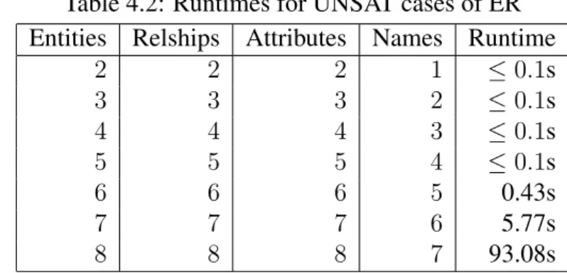
4.2 Runtimes for UNSAT cases of ER . . . 61
5.1 Comparison of approaches when verifying a small model . . . 71
5.2 Comparison of approaches when verifying a medium size model . . 71
5.3 Comparison of approaches when verifying a large model . . . 71
6.1 Definition of the CSP used to tighten verification bounds . . . 78
6.2 OCL Operations on Numeric and Boolean Types . . . 81
6.3 Boolean Operations Over Collections . . . 83
6.4 Other Operations Over Collections . . . 85
6.5 OCL Operations on Strings . . . 88
6.6 Input UML/OCL models. . . 89
6.7 Experimental results (I) . . . 90
6.8 Experimental results (and II) . . . 91
8.1 Expressions Involving Boolean Operators . . . 111
8.2 Expressions Featuring Boolean Functions in the Context of a Col-lection . . . 112
8.3 Boolean Expressions Involving Arithmetic Operators . . . 113
8.4 Other OCL Functions . . . 114
8.5 Boolean Expressions And Their Negated Equivalents . . . 115
9.1 Nodes and arcs generated out of OCL operations in the context of a collection . . . 129
9.2 Generation of nodes and arcs out of OCL iterative operations . . . . 130
9.3 Generation of nodes and arcs out of boolean OCL operations . . . . 131
2.1 MDA 4-layer architecture . . . 23
2.2 Relationship between models and model transformations . . . 24
4.1 Running example: (a) Metamodel for ER diagrams, (b) OCL invari-ants constraining the choice of identifier names. . . 54
4.2 EMFtoCSP architecture . . . 57
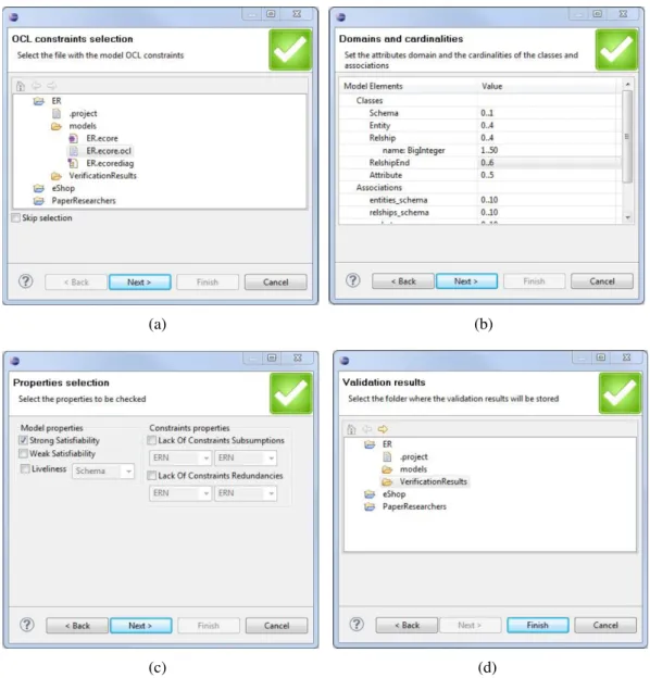
4.3 EMFtoCSP Graphical User Interface. . . 59
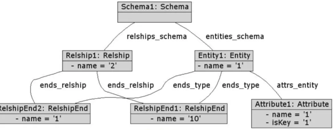
4.4 Valid instance of the running example model . . . 60
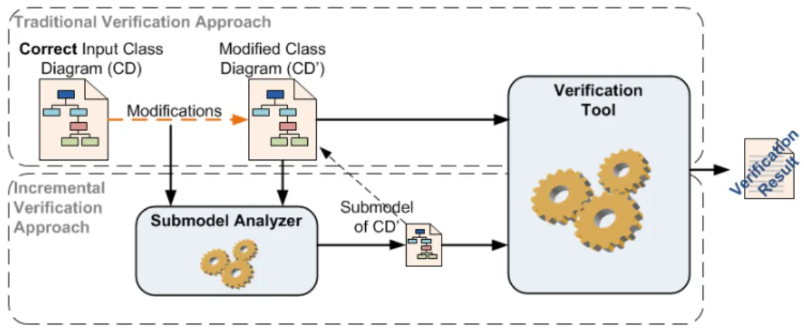
5.1 Traditional Verification vs Incremental Verification . . . 64
5.2 Association Cardinalities and Strong Satisfiability . . . 67
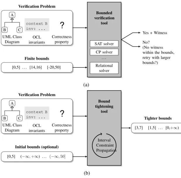
6.1 Comparison of verification approaches: (a) Typical flow with a bounded verification tool, (b) Approach proposed. . . 76
6.2 UML/OCL class diagram used as example. (a) diagram (b) OCL constraints . . . 77
7.1 Mixed approach to model transformation testing . . . 97
8.1 Two versions of the metamodel for the examples used throughout the paper. . . 108
8.2 Results of two different partition analyses over the metamodel ex-ample. . . 109
8.3 Overall picture . . . 110
8.4 Overlapping and partitions when generating test models. . . 117
9.1 Example: (a) Source Metamodel, (b) Target Metamodel (c) Model Transformation Definition. . . 123
9.2 ATLTest: Overall picture . . . 126
9.3 Actions to carry out when applying entry 10 in Table 9.3 to the example . . . 130
9.4 Actions to carry out when applying entry 11 in Table 9.3 to the example . . . 132
9.5 Dependency graph of the example, made up by two connected com-ponents . . . 133
I
Introduction and Basic Concepts
1
Introduction
1.1
Motivation
Computers and software have become essential in the modern society, exert-ing an enormous impact in the way we produce and consume goods and services. There are examples everywhere: financial systems are highly computerized, the majority of money transactions being merely a data exchange among computers; transportation, from intelligent navigation systems to ships, trains, airplanes or cars that are fully loaded with electronic equipment; research, where activities like DNA sequencing or space exploration would not be possible without computers; health-care, where computers store medical records, or are essential part of complex equip-ment such as monitoring systems or medical imaging systems; communication, with computers being an integral part of TV and radio broadcasting systems, electronic mail systems or video conferencing systems; recreation, where holiday packages or popular event tickets are mostly sold online; and so, the list goes on and on.
The immediate effect of all this is that, unsurprisingly, software industry has experimented an exponential growth in the last decades. What is more, far from slowing down, that tendency is accelerating. With modern societies constantly de-manding for more and better products and services, which in its turn, requires more and more complex software systems, today, software industry is growing at an un-precedented pace. This growth implies that first, more people work in activities related to the software industry, and second, that new and more powerful tools and techniques appear every day to develop complex software as easy as possible.
Even though all this describes a bright present and a promising future for the software industry, truth be told, there are also some concerns, especially when it
comes to aspects like quality, absence of errors, reliability and the like. Although ensuring software correctness is not a new challenge [1], but an old one that ware engineers continue to struggle with, the ever-increasing complexity of soft-ware projects, along with the enormous pressure to reduce costs and time to market are making it even more challenging. This is especially worrisome when looking at the consequences that software failures in critical systems can cause. A simple look at Wikipedia1 reveals that, in the best-case scenario, these failures provoke substantial losses of money (as an example, the investment to solve the Y2K bug surpassed the amount of 100 billion dollars, in US only), but in the worst one, the cost is paid in the form of human lives.
Software industry is obviously well aware of these problems and, consequently, substantial research efforts have been and continue to be made to alleviate them. To date, the most popular trends to address this challenge are commonly referred to as software verification and software testing. Software verification comprises those approaches based on the use of formal analysis techniques to prove software correctness. Software testing, on the other hand, usually refers to those approaches that try to find errors in software by systematically running it with a set of inputs for which the expected output is known, and then comparing the actual outcome with the expected one. However, and despite the popularity of these approaches, research efforts have not only focused on the discovery of mechanisms to improve the reliability of software developed by traditional or conventional means. On the contrary, there are relatively new software development paradigms and methodolo-gies that are also gaining traction, such as Software Product Lines (SPL) [2] or Model-Driven Engineering (MDE) [3], as promising ways of developing more reli-able software.
In the particular case of MDE, the main idea is the utilization of models as first-class citizens of the software development process. In an MDE-based software development process, the software is not coded by hand, but by designing and cre-ating a number of models to be successively and (semi)automatically transformed into more refined models, and eventually into the code comprising the new software system. This way, by increasing the abstraction level and reducing the effort made in labor-intensive and error-prone manual tasks such as coding, the amount of errors in the final software system may be reduced.
Although what MDE promotes sounds promising, truth is, an MDE-based soft-ware development process also requires the presence of additional mechanisms to try to ensure its reliability. When MDE is applied to the development of complex software, the complexity of models and model transformation involved in the pro-cess tends to increase. This turns their creation and edition into error-prone tasks that endanger the reliability of the whole process, and therefore the soundness of
the resulting software. Thus far, the research efforts made to alleviate this have consisted in trying to adapt software verification and software testing techniques to the reality of models and model transformations of MDE. Unfortunately, as of this writing, the tools and techniques resulting from these efforts do not enjoy a great deal of success. For this reason, in this thesis, we try to find out what are the reasons that are preventing a wider adoption of these tools, and propose new mechanisms and techniques to try to change this.
1.2
Objectives and Contributions of this Thesis
The objective of this thesis is to improve the landscape of approaches devoted to try to ensure quality and absence of errors in models and model transformations. In particular, the focus is on the analysis of approaches devoted to the verification of static models, which are arguably the models more commonly adopted at the time of describing the specification of a software system [4]. The intent is to develop new mechanisms and to make the existing ones more efficient, thus facilitating their wider adoption. Additionally, the role that these approaches can have at the time of testing model transformations is also studied. As a consequence of this, several techniques where verification approaches are used for the generation of test data are also proposed.
More specifically, the contributions of this thesis are:
– A mechanism aimed at ensuring static model correctness based on constraint programming called EMFtoCSP.
– Two mechanisms aimed at improving the efficiency of model verification ap-proaches.
– A mechanism devoted to the generation of input test data for model transfor-mation testing, based on the analysis of model transfortransfor-mation internals. – A mechanism devoted to the generation of input test data for model
transfor-mation testing, based on the analysis of the model transfortransfor-mation specifica-tion.
1.3
Outline of the Thesis
The rest of this thesis is structured as follows:
– Chapter 2 introduces some basic terminology that will be commonly em-ployed throughout this thesis. It constitutes, along with this chapter, the in-troductory part.
– Chapter 3 presents the current landscape in the field of static model verifi-cation. The existing tools and techniques are analyzed and classified, some
weaknesses are identified, and several improvement proposals are suggested. – Chapter 4 presents EMFtoCSP, a tool for the verification of static models based on Constraint Programming. The tool belongs in a family of model verification tools that limit the search space where to look for a solution of the verification problem. This family of tools, commonly referred to as bounded verification approaches, is gaining popularity, as limiting the search space has proved itself as an effective method to increase the efficiency of model verification tools.
– Chapter 5 presents the first technique for improving the efficiency of verifi-cation tools. Given a correct model and a series of modifiverifi-cations, it consists in determining which parts of the resulting model may impact model correct-ness. The intent is to limit the verification analysis to those parts, omitting the rest of the model in the process. We call it incremental verification of models. – Chapter 6 presents our second technique for improving the efficiency of ver-ification tools. In this case, the technique addresses one of the most important flaws of bounded verification approaches: manually setting the search space boundaries. The technique presented in this chapter analyzes the model to be verified to try to automatically determine what are the appropriate boundaries for the search space. This chapter, along with Chapters 3, 4 and 5 make up the second part of this thesis, devoted to verification tools, and techniques to improve their effectiveness.
– Chapter 7 presents the state of the art in the field of model transformation testing, describing the existing approaches and their weaknesses. Some im-provement proposals are also suggested.
– Chapter 8 introduces a tool for the generation of input test data for model transformation testing, based on the analysis of model transformation inter-nals. This tool is based on the EMFtoCSP tool presented in Chapter 4, and is the first proposal on how static model verification tools can be of assistance to test model transformations.
– Chapter 9 introduces a second tool, also for the generation of input test data for model transformation testing, but in this case, it is based on the analysis of the model transformation specification. As it was the case for the tool of Chapter 8, this tool also relies on EMFtoCSP. It is the second proposal showing how to use static model verification tools to assist in the process of testing a model transformation. This chapter, along with Chapters 7 and 8 constitute the third part of this thesis, oriented to discuss the role static model verification tools may play in model transformation testing.
– Chapter 10 draws the conclusions of this thesis and ideas for future research. It constitutes in itself the last part of this document.
1.4
List of Publications
Several parts of the work conducting to this thesis have been published in the following papers (listed in reversed chronological order)
1. Carlos A. González and Jordi Cabot, Test Data Generation for Model Trans-formations Combining Partition and Constraint Analysis, 7th Int. Conf. on Model Transformations (ICMT), Springer, Lecture Notes in Computer Sci-ence, volume 8568, pp. 25 - 41, 2014.
2. Carlos A. González and Jordi Cabot, Formal verification of static software models in MDE: A systematic review, Elsevier Information and Software Technology Journal, Volume 56, Number 8, pp. 821 - 838, 2014.
3. Carlos A. González and Jordi Cabot, ATLTest: A White-Box Test Genera-tion Approach for ATL TransformaGenera-tions 15th Int. Conf. on Model Driven Engineering Languages and Systems (MODELS) Springer, Lecture Notes in Computer Science, volume 7590, pp. 449 - 464, 2012.
4. Carlos A. González and Fabian Büttner and Robert Clarisó and Jordi Cabot, EMFtoCSP: A tool for the lightweight verification of EMF models, Proceed-ings of the workshop “Formal Methods in Software Engineering: Rigorous and Agile Approaches, FormSERA” , pp. 44 - 50, 2012.
2
Basic Concepts
This chapter introduces some of the basic terminology used throughout this the-sis, with the intent of facilitating the contextualization of the work presented in Parts
II andIII. In particular, it gives a brief overview of the concepts of Model-Driven Engineering (MDE), software verification, software validation and constraint pro-gramming.
2.1
Model-Driven Engineering
One of the most powerful weapons in the arsenal of the software engineer is the ability to abstract complexity away. Abstraction facilitates reasoning about com-plex real-world phenomena, while retaining only the information that is relevant for a particular purpose, and hiding away nonessential details. When these abstrac-tions are expressed textually, graphically, or as a combination of both, it is typical to refer to them with the word “model”. Models are important elements of all soft-ware engineering activities, but in many cases, they play a secondary role, serving as documentation, or somehow tangentially supporting the software development process.
Model Driven Engineering (MDE in short) is a methodology that seeks to change this, by promoting the utilization of models as first-class citizens in all software en-gineering activities. As stated in [3], the role of MDE consists in defining sound engineering approaches to the definition of models, to their modification (that in the MDE terminology is known as “model transformation”), and their integration within software engineering activities. An immediate consequence of this is that, in MDE, the creation of models goes beyond the process of informally depicting ideas
or real-word phenomena. In MDE, models must feature precise and well-defined syntax and semantics, so that they can be automatically interpreted by a computer.
2.1.1
Modeling and Metamodeling
Models and model transformations must be expressed using some kind of nota-tion, which in MDE receives the name of “modeling language”. In reality, in MDE, everything is a model. An immediate implication of this is that these modeling lan-guages are nothing but models, and therefore as such, they are also expressed using a graphical representation, text, or both combined, and must feature well-defined syntax and semantics. The utilization of models to describe models is known as “metamodeling”. If models are an abstraction of some real-world phenomena, metamodels are abstractions describing the properties of models themselves. Meta-models therefore define a modeling language. It is said, that the Meta-models described by a metamodel conform to that metamodel, pretty much the same way that a given program written in a certain programming language, conforms to the grammar of that programming language.
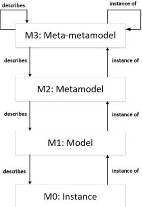
Metamodeling is a recursive process. As a metamodel defines the modeling language that describes the whole class of models represented by that language, a meta-metamodel defines the modeling language that describes metamodels. A popular way of depicting this is by using the four-layered architecture diagram (Fig.
2.1), proposed by the Object Management Group1(OMG) within the Model-Driven Architecture (MDA) framework2. The MDA framework is the particular vision of the OMG about MDE when applied to the development of software.
The layers in Fig.2.1receive the names M0, M1, M2 and M3, respectively. The layer M0 represents the running system where the real-world objects, or instances exist. These instances conform to the models in layer M1, which in their turn, conform to the metamodels in layer M2. That is, models in M1 are described by the modeling languages in M2. Along with this line of reasoning, metamodels in M2 conform to the meta-metamodel in M3, which defines the concepts used in M2, and also the ones used in M3 itself. In this regard, OMG proposes an standard meta-metamodel for M3 called Meta-Object Facility (MOF)3.
2.1.2
Model Classification
Models can be classified in multiple ways, but when it comes to MDE, the two most popular ways of doing this is by considering the part of the system, where the model puts the focus on, or the scope of the modeling language.
1. http://www.omg.org/ 2. http://www.omg.org/mda/ 3. http://www.omg.org/mof/
Figure 2.1: MDA 4-layer architecture
Regarding the first way, when following an MDE approach, it is typical to build different models to gather different aspects of the system under analysis. In these cases, it is quite common to distinguish among two types of models: static or struc-tural models and dynamic or behavioral models.
Static models are those models used to represent, totally or partially, the struc-ture and architecstruc-ture of the system. These models show, in general, a time indepen-dent view of the system. An example of this type of model is the UML4 (Unified Modeling Language) class diagram. Dynamic models, on the other hand, describe the behavior of the system, which may include among other aspects, the description of control or data flows within the system, how the internal state of the different components of the system evolves throughout time, or even the way the system must be used by its users. Some examples of behavioral models are UML sequence diagrams or UML activity diagrams.
Finally, and regarding the scope of the modeling language, it is possible to dis-tinguish two types of modeling languages: Domain Specific Modeling Languages (DSMLs) or General Purpose Modeling Languages (GMLs). DSMLs are designed with the intent of facilitating the creation of models describing the reality of a particular domain or context of interest. GMLs, on the other hand, are modeling languages that can be used to describe models in any domain. The most typical example of GML is UML.
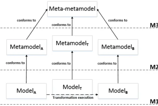
Figure 2.2: Relationship between models and model transformations
2.1.3
Model Transformations
Model transformations are the other key element to MDE. In general terms, they can be seen as a mechanism to transform a model described in a source language into a model described in a target language. That is, model transformations define the rules by which the constructs from the source language are transformed into constructs from the target language.
Fig. 2.2 shows the relationship between models, metamodels and model trans-formations. It can be seen that the model transformation conforms to some kind of model transformation language. This stands to reason, since, as it was mentioned before, everything in MDE is a model. The model transformation language is noth-ing but a metamodel, defined in M2 as any other metamodel, that conforms to the meta-metamodel in M3. It can also be seen in the figure, that model transformations are applied at the modeling level (M1), which makes sense, since are models and not model instances what it is transformed.
Model transformations, as it is the case with models, can be classified in mul-tiple ways. At the top level, it can be distinguished between model-to-model and model-to-text transformations [5]. In the first ones the target is a model, and in the second ones, it is just a set of text strings, like source code or documents. Model-to-model transformations, in their turn, can also be object of multiple classifica-tions. Attending to the source and target metamodels, for example, transformations can be endogenous, when both metamodels are the same, or exogenous, otherwise. If the level of abstraction of the source and target models is considered, it would be possible to talk about horizontal transformations, when the level of abstraction is the same, or vertical transformations, when it differs [6]. Finally, when
con-sidering the way the transformation is specified, it is possible to talk about oper-ational (imperative), declarative and hybrid approaches. Operoper-ational approaches, like Query/View/Transformation (QVT) Operational mappings5, focus on how the transformation itself must be performed, whereas declarative approaches, like QVT Relations6, focus on the relation between source and target metamodels. Finally, hybrid approaches, like the ATL Transformation Language (ATL) [7], combine both. ATL will be described in more detail in PartIII, when talking about testing of model transformations.
2.1.4
The Object Constraint Language (OCL)
The Object Constraint Language (OCL)7 was created with the intent to over-come the limitations shown by UML at the time of precisely specifying detailed aspects of a system design [8]. With the passing of time, OCL has become a key player to MDE and, as of now, it is widely used not only to express integrity con-straints, but also to describe operation contracts or query operations over models; or even to facilitate the description of model transformations or code generation templates, among many other uses.
OCL is a textual, typed, and mostly declarative language. This means that any OCL expression evaluates to a type, and that the presence of imperative statements, like for example assignments, is scarce. One of the most important characteristics of OCL is that it is side-effect free, therefore, OCL expressions do not modify the state of the system.
Due to its extensive use, the analysis of OCL expressions is an integral part of those mechanisms devoted to increase the reliability of MDE approaches, and the techniques presented in this document are not an exception. More details about OCL will be provided in subsequent chapters when needed.
2.2
Software Verification
Software Quality Assurance (SQA) comprises all activities required to make sure that a software product meets certain quality objectives [9]. It is difficult to come up with a precise definition of quality, though. After all, quality means differ-ent things to differdiffer-ent people, and factors like the domain or the point of view are of great influence here [10,11]. To the best of our knowledge, McCall et al. [12] where the first ones in describing software quality in terms of quality factors and quality criteria. Even though with the passing of time, a lot of quality factors have been
5. http://www.omg.org/spec/QVT/1.1/ 6. http://www.omg.org/spec/QVT/1.1/ 7. http://www.omg.org/spec/OCL/2.4/
identified (efficiency, reusability, maintainability, etc) and different quality models have been proposed (ISO/IEC 91268, ISO/IEC 250109, CMMI10), as of now, it is generally accepted that the most important quality factors are those impacting software reliability.
Software verification makes reference to certain procedures and techniques de-voted to identify and solve software problems, that is, to preserve software reliabil-ity. The following definition of “software verification” can be found in the IEEE Standard Glossary of Software Engineering:
“Verification is the process of evaluating a software system or component to determine whether the products of a given development phase satisfy the
conditions imposed at the start of that phase”[13].
However, it is more typical to describe “software verification” by using the def-inition proposed by Barry W. Boehm:
“Am I building the product right?”[14].
It is also quite common to narrow down the meaning of the term “verification”, and use it in the sense of “formal verification”. Formal verification is about the utilization of formal methods to try to prove software correctness. The term formal methods, as stated in [15] refers to the use of mathematical modeling, calculation and prediction in the specification, design, analysis and assurance of computer sys-tems and software. The reason why it is called formal methods is to highlight the character of the mathematics involved.
2.2.1
Formal Methods and Software Correctness
The utilization of formal methods to try to ensure software correctness can be seen, roughly speaking, as a three-step process:
– Building a formal specification of the system under analysis – Reasoning over the specification to prove properties about it
– Obtain, from the formal specification, an implementation of the system Checking software correctness by using, either formal methods, or any other technique, requires the presence of a specification. A specification is, in a broad sense, a description of what the system does and therefore, serves as the frame of reference for all the techniques devoted to try to ensure software correctness. In general, a specification needs to be as precise and unambiguous as possible, but this is especially important when dealing with formal methods. Normally, this is
8. http://www.iso.org/iso/iso_catalogue/catalogue_tc/catalogue_detail.htm?csnumber=22749 9. http://www.iso.org/iso/home/store/catalogue_ics/catalogue_detail_ics.htm?csnumber=35733 10. http://www.cmmiinstitute.com
achieved by using a specification formalism featuring a well-defined syntax and precise semantics. In these cases, it is typical to speak of formal specifications.
Finding the right formalism to fit the specification needs is not an easy task. Actually, there is no shortage of formalisms available, although some of them might be more adequate than others, depending on the perspective followed to build the specification. For example, formalisms like Abstract State Machines (ASM) [16], the B language [17], the Z notation [18], or even automatas [19,20] seem to be a good choice to describe the system as a set of states with system operations being expressed as transitions from one state to another. Alternatively, logic programming languages, such as Prolog [21], functional languages based on λ-calculus [22], such as Haskell [23], or rewriting systems [24], might be adequate to build a specification focusing on the manipulated data, how they evolve, or the way in which they are related.
Once the specification has been built, the next logical step is to prove properties about it. Reasoning about the specification can be done manually, or with the help of computer-based tools. In this last case, the election of the tools to be used will also depend on the formalism employed to build the specification. For example, in the case the specification represents the system as a set of states, model checking [25] could be the right technique to use. On the other hand, if an algebraic formalism is employed, and depending on its expressiveness, using tools like SMT solvers [26,
27] or interactive theorem provers [28,29] could be more adequate.
After proving that a specification features the desired properties, it is the time of trying to obtain a matching implementation. As in the previous steps, there are different alternatives that may be followed. In some cases, the specification is a program that can be executed directly. This is the case of specifications expressed, for example, with logic-based languages like Prolog or functional languages like Haskell, that offer scope for both specification and implementation in the same language. If the specification is not executable, then the implementation must be derived from the specification, which, in its turn, implies the verification of the derivation mechanism employed. These approaches are commonly referred to as “correct-by-construction” software development.
Finally, it is worth mentioning that formal methods can be applied in varying degrees, and not necessarily over all the components of the system under analy-sis. Normally, the level of formalization applied is influenced by factors like the nature of the system or budgetary issues, since the cost of full verification may be prohibitive. Some authors [30] advocate for a light utilization of formal methods in order to facilitate their adoption by the industry. This is known as “lightweight formal methods”.
2.3
Software Validation
Verification techniques are not the only ones available when it comes to preserve software reliability. There is another important group of techniques that fall under the umbrella of what is called “software validation”.
There are multiple definitions of what “software validation” means. For ex-ample, the following definition can be found in the IEEE Standard Glossary of Software Engineering:
“Validation is the process of evaluating software during or at the end of the software development process to ensure compliance with software
requirements”[13].
As it was the case for software verification, Barry W. Boehm also came up with a definition for “software validation” that has become very popular over time:
“Am I building the right product?”[14].
Software validation therefore, like software verification, also makes reference to certain procedures and techniques aimed at trying to identify and solve software problems. When compared to software verification, software validation can be re-garded as a “cheaper” way of establishing a certain degree of confidence over the correctness of a piece of software, and therefore it is especially useful in those sce-narios where software verification techniques cannot be applied, or the cost of their application is too high. Software validation is typically conducted by means of testing techniques, which will be the focus of the next subsection.
2.3.1
Software Testing
Software testing, also known as program testing, can be viewed as the destruc-tive process of trying to find the errors (whose presence is assumed) in a program or piece of software, of course, with the intent of establishing some degree of con-fidence that the program does what it is expected to do [31]. Considering testing a destructive activity has to do with the fact that its goal is not to prove software correctness, but uncover the presence of errors. As Dijkstra stated in [32], testing can be used to show the presence of bugs, but never to show their absence. There are a plethora of testing techniques that can be used at different stages during the software life cycle, but they all can be classified into two big groups:
– Static analysis techniques. – Dynamic analysis techniques.
Static analysis techniques [33], that some authors also called “verification test-ing” [34], are those techniques devoted to the examination of the program code
with the intent of reasoning about the behavior that the software is going to exhibit at runtime. This can be complemented with the examination of other documents, such as design models or requirements documents, if necessary. The main charac-teristic of this type of activities is that they are conducted manually and therefore, do not require code execution to uncover errors. Some techniques that fall into this category are code inspections or walkthroughs [31].
Dynamic analysis techniques [33], on the other hand, do require software execu-tion to expose the presence of bugs. This typically implies following a methodology that can be summarized in the following three points, which are repeated a certain number of times, until a specific stopping condition is met.
– Determine the adequate input data to test the program with. – Run the program with the input data obtained from the first stage.
– Analyze the outputs yielded by the program with the intent of uncover errors. The information needed to conduct these three steps is typically bundled into an item called “test case”. This information includes, at least, the input data values the program is going to be run with; any other execution condition required by the test case, like for example a specific hardware configuration or a certain database state; and the expected outputs to be produced during the program execution. In relation to this last point, the expected outputs are paramount, since without them, it is impossible to determine whether the execution of the test case uncovered any errors. In testing terminology, it is usual to use the word “oracle” [35] to make reference to that program, process or body of data that specifies the expected outcome for a set of test cases as applied to a tested object. An oracle can be as simple as a manual inspection or as complex as a separate piece of software.
It is generally accepted that the more test cases are created and the more time is spent running the software, the higher is the probability of finding errors and therefore ending up with a more reliable software. However, since the number of test cases that can be created to test a piece of software is potentially infinite, it is necessary to establish some strategy to carry out testing in an effective way.
Two of the most prevalent strategies are black-box testing and white-box test-ing. The main difference between the two is the kind of information considered to generate test cases, the rest of the testing process being essentially the same.
When following a black-box approach, the tester does not consider any infor-mation related to the internal structure of the system under test. She “knows” what it does, but not how it does it. It is a black-box, hence its name. Because of this, the creation of test cases by means of black-box approaches is usually based on infor-mation gathered from the software specification, requirements documents or some domain knowledge the tester might have. In light of this, black-box approaches are quite adequate to uncover errors related to software requirements or the software specification.
White-box approaches, on the other hand, focus on the internal structure of the software to be tested, and therefore, the presence of the source code is required. When the tester applies a white-box strategy, the test case generation process is driven by information such as the presence of branches or loops in the software code, or more generally, the control flows and data flows that can be inferred from the analysis of that code. All this makes white-box approaches especially suitable for the discovery of logic errors.
In spite of the variations among the different strategies available, it is generally accepted that generating test cases through a combination of distinct testing strate-gies, maximizes the probability of uncovering errors and therefore, the success of the testing experience.
It is also important to mention that testing techniques can be applied in varying degrees and at different stages during the software life cycle. In this regard, it is typical to talk about four different “levels of testing” [36], namely unit testing, inte-gration testing, system testing, and acceptance testing. Unit testing makes reference to the evaluation of system components in an isolated manner to detect functional or structural defects. Integration testing focuses on the evaluation of the interac-tion among different parts of the system, so the focus usually spreads over several components somehow related to each other. System testing checks the system as a whole, not only to determine the presence of defects, but also to evaluate quality as-pects like performance, usability, security or the documentation, among others. The last testing level, acceptance testing has to do with ensuring that the system satisfies the initial requirements. and therefore meets the needs of its end users. It is impor-tant to remark that these “levels of testing”, although popular, are not the only types of testing available. Actually, they do not even cover all the stages that typically occur during the software life cycle. For example, another type of testing known as regression testing, may be especially useful during the software maintenance stage. Finally, it is worth noting that there is not a preferred or standard way to integrate testing techniques within the rest of activities that take place during the software development life cycle. However, a popular software development paradigm like Test Driven Development (TDD) [37] may facilitate this.
2.4
Constraint Programming
Constraint programming, as stated in [38], is the study of computational systems based on constraints. The idea behind constraint programming is to solve problems by stating requirements (constraints) about the problem area, and then finding a solution satisfying all these constraints. As described in [39], in its most basic form, constraint programing consists in finding a value for each one of a set of
problem variables where constraints specify that some subsets of values cannot be used together. The problems addressed by Constraint Programming are known as Constraint Satisfaction Problems (CSP).
Informally speaking, a constraint can be viewed as a relation between variables and the values they can take. The term “constraint” has been typically used by physicists and mathematicians for a long time, but when it comes to computer sci-ence, though, it was not until the early sixties that Ivan Edward Sutherland adopted it for the first time, while working on the Sketchpad project11, in the area of com-puter graphics. In particular, he proposed the following definition, that can be found in his PhD thesis:
A constraint is “a specific storage representation of a relationship between variables which limits the freedom of the variables, i.e., reduces the number of
degrees of freedom of the system”[40]
After this pioneering work, the earliest ideas leading to the concept of constraint programming came from the field of Artificial Intelligence (AI) in the sixties and seventies. One of the major breakthroughs was the formalization of a CSP for the first time, which was made by David L. Waltz [41]. Formally speaking, a CSP can be represented as the tuple CSP = hV, D, Ci where V denotes the set of variables, D the set of domains, one for each variable, and C the set of constraints. It is typical to describe the constraints in a CSP by means of a combination of arithmetic expressions, mathematical comparison operators and logical operators.
A solution to a CSP is an assignment of values to the variables such that all constraints are satisfied. As described in [42], there are different techniques that can be used for solving a CSP, namely: domain specific methods, general methods or a combination of both. The expression “domain specific methods” makes reference to those implementations of special purpose algorithms, typically provided in the form of libraries, like for example, algorithms for the resolution of systems of equations, or linear programming algorithms. On the other hand, “general methods” has to do with those techniques to reduce the search space where to look for a solution (which are commonly referred to as constraint propagation techniques); and with specific search methods, such as backtracking or branch and bound search. For efficiency reasons, whenever possible, domain specific methods should prevail over general methods. From an architectural standpoint, the tools used to solve CSPs are typically developed as frameworks, with built-ins supporting different search methods and constraint propagation techniques, accompanied by domain specific methods in the form of libraries, often called constraint solvers.
When it comes to the actual resolution of CSPs, these tools attempt to assign values to variables following a certain order. If the partial solution violates any
straint, then the last assignment is reconsidered by either trying a new value in the domain, or backtracking to previous variables, if there are no more values available. The utilization of constraint propagation techniques to identify unfeasible values in the domain of unassigned variables, helps to speed up the process by pruning the search tree. The process continues until a solution is found or all possible assign-ments are considered. In this second case, the CSP is called unfeasible. What can be followed from all this, is that in order to ensure termination, the domains of the variables must be finite.
Finally, it is also important to mention, that in order to solve a CSP with computer-based tools, the CSP must be expressed using some kind of notation. Popular alter-natives here are the utilization of object-oriented/procedural languages or declara-tive notations. In the first case, well known languages like C++, Java or .NET can be used, as for example, it is the case with the IBM CPLEX CP Optimizer12. In the second case, the Constraint Logic Programming (CLP) paradigm proposed by Jaffar and Lassez [43], which merges constraint solving and logic programming is espe-cially popular. An example of a tool which allows representing and solving CSPs using this paradigm is the ECLiPSe Constraint Programming System13, which is at the heart of some of the contributions presented in this thesis.
2.5
Summary
With this chapter finishes the introductory part of this thesis. The objectives have been presented, and some basic terminology has been introduced. In the next part, the focus will be on the first contributions of this doctorate, the ones devoted to improving the landscape of static model verification tools.
12. http://www-01.ibm.com/software/commerce/optimization/cplex-cp-optimizer/ 13. http://eclipseclp.org
II
Static Model Verification
3
Landscape of Static Model
Verification Approaches
After introducing the basic terminology, in PartII the focus is on the discov-ery of techniques to increase the efficiency of tools devoted to the verification of static models. Static models are important because, as it was mentioned in previous chapters, are possibly the models more commonly used when specifying a software system [4]. A classical example of static model is the UML class diagram so, from now on, it will be common to make reference to class diagrams constructs, such as classes, associations or OCL constraints.
In this first chapter of PartII, the target is to depict what the current landscape regarding static model verification is. We will start by stating some generalities about the matter and after that, we will describe what are, as of this writing, the existing approaches in the field. To finish the chapter, we will discuss certain aspects that can be improved. How to address some of them will be the objective of the rest of chapters in this part.
3.1
Generalities About Static Model Verification
Formal verification of static models makes reference to those approaches de-voted to proving model correctness by means of the utilization of formal methods and formal analysis techniques. However, and although some may find it surpris-ing, there is no a universal definition of what “model correctness” means. On the contrary, there are many ways a given model may be considered “correct”. Because of this, it is typical to refer to model correctness as the ability of the model under
analysis to satisfy one or more correctness properties. These properties state certain characteristics the model must feature in order to be considered correct.
In general terms, it is possible to classify correctness properties into two big groups: the group of properties about the instantiability of the model and the group of properties about the relationship among constraints. Regarding the properties that fall into the first group, the most important one is called “satisfiability”. A model is consider “satisfiable” when it is possible to create instances out of it. As we will see in the following section, some of the studies analyzed distinguish among different “flavors” of satisfiability: for example, strong satisfiability means that the legal model instance must include instances of all the classes and associations in the model, and weak satisfiability, being less strict, does not enforce the instantiation of all classes and associations. Another property belonging to this first group is “liveliness of a class”, that is to check whether it is possible to create legal instances of the model including at least one instance of a certain class. This property can be regarded as a particular case of satisfiability. In general, satisfiability is of special importance because the rest of correctness properties can be expressed in terms of this property. When it comes to the second group of correctness properties, some of the existing verification approaches are able to check the presence of redundant constraints in the model, some others can check whether two given constraints in the model contradict to each other, or even if some constraints are subsumed by others.
When it comes to the way verification tools in this field work, the verification process is not very different than the general approach described in Chapter2. Ver-ification of static models can be divided in two different stages. In the first one, the formalization takes place, that is, the model along with the correctness properties to be checked are somehow represented in the formalism of choice. With the formal representation in place, the second stage takes over. It consists in reasoning over that formalism, usually with the help of some specialized tool, to see whether the correctness properties are satisfied or not.
The completeness and degree of automation of this reasoning process is strongly dependent on the degree of support given to the OCL. This is because supporting OCL in its full generality leads to undecidability issues, as stated in the work of Berardi et al. [44]. In this scenario, verification approaches that are complete are also user-interactive (i.e. they need help from the user to steer the verification pro-cess). This can be problematic since it usually requires from users a non-negligible expertise in the formalisms employed. Because of this, the majority of approaches supporting OCL in its full generality are automatic and ensure termination, but this is achieved at the expense of its completeness. This is done by following a bounded verification approach, in which users typically have to configure beforehand certain parameters to drive the reasoning process, but once it is launched, user intervention
is not required. In particular, it is typical of these approaches to put in the users’ hands the responsibility of setting the search space boundaries where to look for a solution of the problem. In this scenario, results are only conclusive if the model is found to be correct. Nothing can be concluded otherwise. It might be that the model is incorrect, or that it is correct, but the solution to the problem lies outside the search space considered. On the other hand, approaches supporting only a sub-set of OCL are automatic and complete since they are not affected by the undecid-ability issues stated in [44]. Finally, and before presenting the existing verification approaches it is worth mentioning that in the majority of cases when a model is found to be correct, these tools yield a valid instance of that model as a proof of correctness.
3.2
Static Model Verification Approaches
While trying to fulfill the objectives of this thesis, we came across to an im-portant number of scientific papers that, one way or another can be directly related to the formal verification of static models. Some of these works put the focus on formalization aspects, some others on theoretical aspects regarding the reasoning stage, and finally some others present verification tools. In all cases, these works are part of coarse-grained studies where each paper contributes to a specific part of the verification problem. In particular, we have identified up to 17 different studies that are summarized in Table 3.1. In what follows, we present these studies and their main characteristics. To facilitate their contextualization, we also add citations to other relevant works, whenever necessary. In those studies complemented with the presence of a verification tool, we expand the description to also provide a brief description of the tool itself. Finally, Tables3.2,3.3and3.4summarize our findings to facilitate the reader the comparison of these studies attending multiple factors.
The first study (S1) comprises the works directly related to UMLtoCSP. UML-toCSP, developed by Cabot et al. [45,46], is a Java tool for the formal verification of UML/OCL models based on constraint programming. The tool works by translating a class diagram, its OCL constraints and the desired verification properties into a CSP. The data input interface is a bit limited. The class diagram must be expressed in an XMI format created with ArgoUML1, and the OCL constraints must be pro-vided in a separate text file. In general, the GUI looks outdated. The CSP built by the tool is expressed as a Constraint Logic Program (CLP), this is because, for the resolution of the CSP, the tool relies on the ECLiPSe Constraint Programming System2, which requires CSPs to be expressed in this notation.
1. http://argouml.tigris.org/ 2. http://eclipseclp.org
Table 3.1: Summary of the 17 studies identified Study Representative Name References
S1 UMLtoCSP [45–47] S2 OCL2FOL [48] S3 FiniteSat [49,50] S4 AuRUS [51–55] S5 DL [44,56–65] S6 OCL-Lite [66,67] S7 OODB [68,69] S8 HOL-OCL [70–72] S9 UML2Alloy [73,74] S10 USE [75–81] S11 BV-BSAT [82,83] S12 PVS [84] S13 KeY [85] S14 Object-Z [86] S15 UML-B [87] S16 CDOCL-HOL [88] S17 MathForm [89]
Table 3.2: Formalization techniques used in each study
Study Formalization Technique
S1 (UMLtoCSP) CSP
S2 (OCL2FOL) FOL
S3 (FiniteSat) System of Linear Inequalities
S4 (AuRUS) FOL
S5 (DL) Description Logics, CSP
S6 (OCL-Lite) Description Logics
S7 (OODB) TQL++
S8 (HOL-OCL) HOL
S9 (UML2Alloy) Relational Logic
S10 (USE) Relational Logic
S11 (BV-BSAT) Bit-vector Logic
S12 (PVS) HOL
S13 (KeY) Dynamic Logic
S14 (Object-Z) Object-Z
S15 (UML-B) B
S16 (CDOCL-HOL) HOL
S17 (MathForm) Mathematical Notation
Although UMLtoCSP was designed with the intent of supporting OCL con-straints in its full generality, as of this writing, not all the OCL constructs are sup-ported. Even though, the tool features some notable characteristics: user interven-tion during the reasoning process is not required (i.e. it is automatic) and termi-nation is ensured. This is possible because the tool follows a bounded verification
approach, which also means that, as typical of these approaches, the verification process is not complete. Regarding correctness properties, UMLtoCSP supports the verification of strong satisfiability, weak satisfiability, liveliness of a class, lack of constraints subsumption and lack of constraint redundancies. If the verification process succeeds, the tool presents an image of a valid model instance as a proof. To do this, it requires the presence of the graph visualization package Graphviz3.
Unfortunately, the last version available (June 2009) presents several bugs and 64-bit platforms or modern operating systems like Windows 7 or Windows 8 are not supported. Besides, it is not unlikely for the verification process to take quite some time in many occasions. The source code is not available on the website.
UMLtoCSP was later on complemented with the work of Shaikh et al. [47] consisting in the development of a slicing technique for UML/OCL class diagrams. The presence of this technique turned UMLtoCSP into a more efficient tool when verifying weak satisfiability or strong satisfiability.
The second study (S2) is about the work of Clavel et al. [48] on formalizing and reasoning over OCL constraints. In this work, a mapping from a subset of OCL into FOL is proposed with the intent of supporting verification using automated reason-ing tools like Prover94, an automated theorem solver, and Yices5, a SMT solver. In particular, the authors propose reasoning on their own notion of (unbounded) unsatisfiability of OCL constraints over a class diagram.
The third study (S3) collects the works of Azzam Maraee and Mira Balaban, who developed a linear programming based method for reasoning about finite sat-isfiability of UML class diagrams with constrained generalization sets [49]. In the authors’ words, finite satisfiability is the problem of deciding whether a given class has a finite, non-empty extension in some model. Their method builds on top of the work of Lenzerini and Nobili [90], which is based on the transformation of the cardinality constraints into a set of linear inequalities whose size is polynomial in the size of the diagram. This way, the finite satisfiability problem is reduced to the problem of finding a solution to a system of linear inequalities. The algorithm proposed, called “FiniteSat”, was later on improved [50] to handle all the types of constraints included in an enhanced version of the Description Logics to class diagrams translation presented in [44].
The fourth study (S4) congregates the verification works based on the CQC Method [91], a mechanism to perform query containment tests on deductive database schemas, that has also been used to determine properties like satisfiability or predi-cate liveliness over this type of schema. In this regard, Queralt et al. presented Au-RUS [51], a tool for assessing the semantic quality of a conceptual schema
consist-3. http://www.graphviz.org/
4. http://www.cs.unm.edu/ mccune/mace4/ 5. http://yices.csl.sri.com/
ing in a UML class diagram complemented with OCL arbitrary constraints, which extends SVTe [92], a relational database schema validation tool. Apart from the satisfiability of the conceptual schema, AuRUS can verify liveliness of classes or associations and redundancy of constraints, without requiring user intervention dur-ing the reasondur-ing process. The tool works [52] by first translating both, the class diagram and the OCL constraints into a set of first-order formulas that represent the structural schema, and then verifying, by using the CQC Method, whether the sup-ported properties hold. In the case that the properties do not hold, the tool is able to give the user a hint about the changes of the schema that are needed to fix the problem identified [55]. AuRUS does not guarantee termination when dealing with general OCL expressions, but it does so [53] when dealing with a specific subset of constraints.
Finally, in [54] the authors presented several improvements, like an enhanced version of the conceptual schema to logic translation, or refinements on the mecha-nism presented in [53] which is used by AuRUS to determine whether the reasoning process will terminate or not.
The fifth study (S5) compiles the work developed by Calvanese et al. on reason-ing over entity-relationship models and UML class diagrams since the year 2002. Related to this, Cadoli et al. [56–58] developed an approach to encode the problem of finite model reasoning (i.e. checking whether a class is forced to have either zero or infinitely many objects) in UML class diagrams as a CSP that is solved by relying on the use of off-the-shelf tools for constraint modeling and programming. These works exploit the encoding of class diagrams in terms of Description Logics proposed by Berardi et al. [44,63,64] and Cali et al. [65], to take advantage of the finite model reasoning techniques developed for Description Logics in [93], based on reducing the problem of reasoning on a Description Logics knowledge base to the problem of finding a solution for a set of linear inequalities.
Moreover, the work of Berardi et al. [44,63] has also served as a basis for the complexity analyses conducted by Artale et al. [59–62] which have established im-portant results about the problem of verifying full satisfiability over different vari-ants of UML class diagrams or entity-relationship models.
The sixth study (S6) contains the work related to OCL-Lite [66,67], a frag-ment of OCL that ensures termination and completeness when reasoning on UML conceptual schemas enriched with arbitrary constraints within the bounds of this fragment. Apart from the identification of such a fragment, the authors propose an encoding of UML class diagrams enriched with constraints within its bounds in Description Logics. In this regard, they take advantage of the works developed by Calvanese et al. that have been described in [S5]. Finally, they show how it is pos-sible to use existing reasoners to provide reasoning support to check properties like schema satisfiability or constraint redundancy over these models.
The seventh study (S7) refers to the work of Anna Formica on checking finite satisfiability of database constraints. In particular, a decidable graph-theoretic ap-proach to finite satisfiability checking is proposed in [68]. This approach, which is limited to integrity constraints involving comparison operators, was later on ex-panded in [69] to cover cardinality constraints among others. In both cases, the database schemas are described using fragments of TQL++ [94], an object-oriented data definition language aimed at modeling the structural aspects and integrity con-straints of object-oriented database models [95].
The eighth study (S8) is about the formal proof environment HOL-OCL [70], developed by Brucker and Wolff. HOL-OCL is an interactive proof environment that can be used to analyze UML/OCL models created with ArgoUML. It has been integrated into a framework supporting a formal model-driven engineering process, which is described in [71]. HOL-OCL works by automatically encoding the class diagram along with the OCL constraints in Higher-Order Logics (HOL). This en-coding, which is described in detail in [72], can then be used to reason over the model by means of the interactive theorem prover Isabelle [96]. A drawback of HOL-OCL is that it is a tool extremely hard to use for the user not familiarized with formal methods and Isabelle. Not even its installation is trivial, since it presents an important number of prerequisites. Regarding the verification stage is, in general, interactive, and requires building Isabelle theories as part of the process. Last ver-sion is 0.9.0 (the year is not indicated) and the downloadable package includes the source code.
The ninth study (S9) makes reference to the works about UML2Alloy [73,74], which is the name of a Java standalone application developed by Anastakasis et al., that can be used to check the satisfiability of a UML class diagram enriched or not with OCL constraints. UML2Alloy, as it can be inferred from its name, works by transforming the model to be verified into the relational logic of Alloy6[97], which is then fed into the SAT solvers embedded within the Alloy Analyzer (bundled with the tool). As UMLtoCSP, the GUI looks outdated. The different steps are distributed in tabs. Once the model is loaded, it is necessary to set the boundaries of the search space and determine how OCL statements will be transformed into Alloy. Regarding the verification process in itself, UML2Alloy, as UMLtoCSP, follows a bounded verification approach (i.e. it is not complete). If it succeeds, the tool presents a valid model instance as a proof. This instance can then be exported as a PNG image or a PDF document. a drawback of this tool is that it is a bit unintuitive, forcing users to run actions like parsing XMI files or transform the input data to Alloy, explicitly. Last version is 0.52 Beta, built on May 2009. The source code was not available on the website.
The tenth study (S10) relates to the work of Gogolla et al. around the USE