HAL Id: hal-00794311
https://hal.inria.fr/hal-00794311
Submitted on 25 Feb 2013
HAL is a multi-disciplinary open access
archive for the deposit and dissemination of
sci-entific research documents, whether they are
pub-lished or not. The documents may come from
teaching and research institutions in France or
abroad, or from public or private research centers.
L’archive ouverte pluridisciplinaire HAL, est
destinée au dépôt et à la diffusion de documents
scientifiques de niveau recherche, publiés ou non,
émanant des établissements d’enseignement et de
recherche français ou étrangers, des laboratoires
publics ou privés.
A UML-integrated test description language for
component testing
Simon Pickin, Claude Jard, Thierry Heuillard, Jean-Marc Jézéquel, Philippe
Desfray
To cite this version:
Simon Pickin, Claude Jard, Thierry Heuillard, Jean-Marc Jézéquel, Philippe Desfray.
A
UML-integrated test description language for component testing. Lecture Notes in Informatics (LNI), Oct
2001, Dortmund, Germany. �hal-00794311�
A UML-integrated test description language for
component testing
Simon Pickin
1, Claude Jard
1, Thierry Heuillard
2Jean-Marc Jézéquel
1, Philippe Desfray
3 1 IRISA/CNRS Campus de Beaulieu 35042 Rennes Cedex France [email protected] 2France Télécom R&D Technopole Anticipa 22307 Lannion Cedex France [email protected] 3 Softeam 144, Champs Elysée 75008 Paris France [email protected]
Abstract: A mass market in reusable components demands a high level of nent quality, testing being a crucial part of software quality assurance. For compo-nents modelled in UML there are significant advantages to using UML also for the test description language. Since we wish to describe tests of non-trivial temporal ordering properties, we define our test description language based around UML interaction diagrams, seeking inspiration from the work on conformance testing of telecom protocols. We aim at a fully integrated approach which can be captured in a UML component testing profile.
1 Introduction
After more than 30 years as a desideratum, component-based software is finally becom-ing a reality. However, a truly mass market in reusable components demands a high level of component quality. In a software component economy, the provider needs to have confidence that his or her components will work correctly in widely-differing contexts, while the client needs to have a clear, simple and reliable path to integrating components in his or her application that ensures their correct functioning. The different actors in-volved in the provision and acquisition of software components therefore need methods, tools and techniques to verify, test and certify them. Testing is a crucial part of software quality assurance and the potential gains in productivity which can be obtained by auto-mation of the testing process are large.
We seek to generalise current object and component testing approaches using a UML-integrated test description language as described in Section 3. This language is designed to be the pivot formalism in a UML test environment incorporating automated test gen-eration from UML models as briefly sketched in Section 8.
The notion of test currently used in many approaches to object-based software testing, e.g. [G01] is restricted to checks on the result of single method invocations using fixed parameters, or possibly to the execution of a sequence of such checks. In recognition of the need for data partitioning [Ra01] adds a rudimentary facility for specifying repre-sentative data values for simple data types. The tool presented in this latter article also
allows tests of very simple invocation scenarios to be specified using UML sequence diagrams. However, the use of asynchronous messages, call-backs, branching, explicit concurrency and active objects leads to more complex behaviour than that which can be treated with this approach.
The problems associated with temporal ordering have been extensively explored in the telecom domain, as witnessed by the development of the ISO standard testing language TTCN [Is92b]. We thus seek inspiration from telecom testing, and in particular from the work carried out on conformance testing of telecom protocols. Note that care must be taken over terminology clashes between the software testing and telecom testing do-mains. In order to describe component tests ranging from simple synchronous invoca-tions with checking of return values to tests of complex temporal ordering properties, as well as allowing for tests derived from post conditions and invariants, a specific test description language is needed. As mentioned above, we impose the prior constraint that this test language, hereinafter called ¡TeLa!, be based on UML for the reasons given in Section 3. We clarify the UML basis of our language and show the need to introduce some additional constructs, most of which are of wider interest and relevant to the use of UML in other areas. We also propose a syntax for these additional constructs though our proposals are currently of an exploratory nature.
In the following section we describe some of the basic testing concepts we will need in the rest of the article. In Section 3 we describe our approach and the motivation behind it. In Section 4 we discuss the suitability of UML interactions as the basis for ¡TeLa! and in Section 5 we discuss the constructs we need. An overview of the syntax of ¡TeLa! is given in Section 6 and of the semantics in Section 7. In Section 8 we indicate the place of ¡TeLa! in the UML test environment we are designing and draw conclusions about it.
2 Some Testing Concepts
In the work reported on in this article we are concerned with functional or black-box
testing, that is, testing in which interaction with the component is carried out exclusively
through the interfaces defined in its specification and without reference to lower-level descriptions. The component which is the subject of testing is referred to as the
compo-nent under test (CUT).
It is often the case that the CUT cannot be tested without the presence of other software components. The CUT together with the set of components having some communica-tions which are not to be observed as part of the test (these communicacommunica-tions being either with the CUT or with other such components) is denoted the system under test (SUT). We will refer to all the software in the test setup which is not part of the SUT as the
tester and we will assume that it contains a main test component (MTC), the component
responsible for delivering the test verdict, one of pass, fail or inconclusive, see [Is92a]. Both the tester and the SUT are dynamic in the sense that each may instantiate new components in its respective domain in the course of the test.
A stub is a skeletal or special-purpose implementation of a software module, used to develop or test a component that calls or is otherwise dependent on it. Both the SUT and the tester may contain stubs, SUT stubs being either part of the initial configuration or being created by other SUT stubs. Programming stubs takes up a significant part of
software testing time; we will therefore be interested in test descriptions which lend themselves well to automating stub generation, particularly for pure server tester stubs.
3 Motivation
and
Approach
For components modelled in UML, there are strong pragmatic reasons for using a UML-based test description formalism. Firstly, it will enable the testing environment to be fully integrated into a UML environment. Secondly, it will facilitate the production and comprehension of test descriptions and, in so doing, help to ensure that such descriptions become part of the documentation associated to a component. Finally, it manifests the relation between the tests and the UML model of the application.
Recall that we are interested in black-box testing and among the properties we wish to test are those concerned with correct ordering of the messages interchanged between the SUT and the tester, the latter playing the role of the SUT’s environment. Among the different views used in UML modelling, interactions are clearly the most suited to de-scribing message orderings and therefore the most adequate on which to base our test description language. Sequence diagrams, in particular, are also considered to be espe-cially friendly, as are related formalisms such as MSCs. With simplicity and user-friendliness in mind, we set ourselves the goal of using only the sequence diagram (and possibly collaboration diagram) and class diagram views with the overwhelming empha-sis on the sequence diagrams1. As we explain in the rest of this article, this inevitably involves increasing the expressive power of the latter diagrams. In so doing, we cur-rently do not attempt to maintain an equivalence between sequence diagrams, on the one hand, and collaboration diagrams with superimposed interactions, on the other.
The ETSI standardisation of TTCN-3 [Is92b] testifies to the current interest in MSC-like syntaxes for test languages. The latest version of the test language TTCN, which aims at a broader class of systems than its predecessors, comes equipped with a graphical syntax [Et01a] based on the MSC language [It00]. However, there are significant differences between the MSCs/TSCs and UML sequence diagrams. Moreover, in our opinion, a general-purpose testing language such as TTCN is unnecessarily complex for component testing (as well as for our target component test designers) and many of its features would be difficult to express in a UML-based test description language. We thus incor-porate some of the features of TSCs and strive to maintain a certain coherence with them, while at the same time trying to remain as close as possible to the UML 1.4 stan-dard, and particularly to the metamodel.
In spite of the desire to remain close to the UML standard, the range of behaviour we wish to treat makes the introduction of some new constructs inevitable. In Section 5 we explain the need for the constructs introduced. Where feasible, rather than extending the UML syntax, we propose adaptations of existing UML syntactic elements. Moreover, we derive a mapping to the current metamodel for each of these adaptations and extensions, with a view to incorporating the test description language in a UML component testing profile. In this respect, our approach is more UML-integrated than that of [ESG00], for example.
1
Test synthesis, see Section 8, also requires an object or deployment diagram to describe the initial state of the model.
4 Suitability of UML Sequence diagrams and UML interactions
In this section we examine some of the difficulties in giving a semantics to UML se-quence diagrams representing test descriptions via a mapping to the UML metamodel. 4.1 Messages vs. events
The UML semantics is defined in terms of relations between messages. However, a sequence diagram which is a black-box test description is to be interpreted as a specifi-cation of a test driver. A test driver only implements the behaviour of the instances rep-resenting the tester, and, for each communication with the SUT, only the send, call or receive actions performed by the tester. To obtain a specification of the test program, therefore, we will need to derive an operational semantics in terms of tester events. Such a semantics can be viewed as the projection onto the tester instances of a semantics de-fined in terms of messages. As a consequence of defining the operational semantics via a projection, different sequence diagrams may describe the same test.
4.2 A metamodel mapping in terms of predecessor and activator
The semantics of UML sequence diagrams is described using two relations, predecessor and activator, in a manner similar to the two relations of [La86]. In the case of proce-dural sequence diagrams, the mapping to a metamodel instance is relatively simple. The predecessor describes the ordering relation between outgoing invocations on an instance and the activator describes the causality relation between an incoming invocation and consequent outgoing invocations made by the invoked method.
However, it is difficult to see how this scheme can be generalised to give a realistic se-mantics beyond procedural diagrams, particularly for a test description language. The mere use of asynchronous messages raises questions about the ordering of messages
emitted by an instance being based on the notion of “message completion”, as would
appear to be the case from the definition of the predecessor association [Om01] P.2-129. If the activator relation is the only way to order messages emitted by different instances, some of the messages sent by active objects can never be shown as being ordered with respect to messages sent or received on the emitting instance (unless there is a forward causal connection passing via other objects). Similarly, if activations are not to be asso-ciated to signals (this is not clear in [Om01]), the latter can never be shown as being ordered with respect to other messages sent or received on the receiving instance (unless there is a backward causal connection passing via other objects).
In the presence of branching, guards and explicit concurrency, judging by the number of interpretations to be found in the literature, there does not seem to be agreement on the use of the system of sequence numbers proposed in the UML documentation, which, furthermore, is particularly user-unfriendly. The thread names notation is used for de-noting concurrency, branching or even a mixture of both, and is used in different ways when the threads contain nested calls. The use of loops and branching would cause even more difficulties for this notation, which already seems to be in difficulties.
In the case of asynchronous invocations, particularly between active objects, it is not customary to use focus bars so that no activation relations can be deduced. In this case, according to a strict interpretation of the mapping to the metamodel, the invocations
made by different instances are completely unrelated. In the literature, many examples of UML sequence diagrams involving only asynchronous messages and with no focus bars can be found, e.g. [Et01b]. The interpretation seems to involve a total ordering on all the messages or a total ordering on the messages emitted or received on each instance. How-ever, this interpretation is not usually made explicit and in fact, there is little to support it in the UML documentation. Furthermore, it still leaves open the question of how to interpret diagrams involving both synchronous invocations with focus bars and asyn-chronous invocations / signals without.
Finally, the fact that the explicit causality of the activator relation is the only way to relate messages emitted by different instances means that sequence diagrams are not well-adapted to describing ordering properties in incomplete causal flows. This is a seri-ous impediment to treating part of the application as a black box in a sequence diagram (essential for a functional test language) and limits the use of sequence diagrams at dif-ferent levels of abstraction (very useful for a test objective language, see Section 8). 4.3 A metamodel mapping in terms of predecessor alone
Formalisations such as that of [Kn99] do not address the difficulties discussed in the previous section and therefore do not help us in defining a test description language. One option would be to explore the correspondence between the message flow graphs of [LL95], with their precedence and communication relations, and UML sequence dia-grams, with their precedence and activator relations. However, we choose instead to define a semantics in terms of ordering alone, that is, using only the predecessor relation between metamodel Message objects. The activator relation then only serves to order messages if it falls inside the scope of a coregion operator, see Section 6.2.1.
For a mapping defined in terms of predecessor alone, there are three principle options:
• Minimalist interpretation: lifelines imply no ordering, only a context and a direction
in which ordering relations between message receptions and message emissions can be imposed. A means to explicitly order certain messages emitted on the same life-line may be required (e.g. virtual messages). This interpretation leads to the simplest semantics, in a context where the semantics of a diagram is to be given as a partial ordering between messages rather than events. Moreover, the “message completion” notion used in the definition of the predecessor relations is a local one.
• Maximalist interpretation: lifelines imply an ordering of all messages emitted or
received. A means to explicitly break this ordering in certain cases may be required. This is the most intuitive and user-friendly interpretation and close to the standard MSC interpretation (though the partial-ordering is of messages not events).
• Half-way interpretation: lifelines imply an ordering of all messages emitted but not
those received; messages emitted by different instances are then related by explicitly imposing ordering relations between receptions and emissions on a lifeline as for the minimalist interpretation. A means to explicitly order certain messages received on a lifeline, as well as to explicitly break the ordering for certain messages sent on a lifeline, may be required. This is a more causal interpretation than the maximalist interpretation, c.f. relation with the “race problem” of [MP99].
User-friendliness considerations lead us to choose the maximalist interpretation as the basis for ¡TeLa!. Another advantage is that a richer semantics in terms of partially-ordered events can be defined relatively easily as a refinement.
5 Additional constructs needed in ¡TeLa!
5.1 Internal actions
We need an internal action construct in order to specify events such as assignments. 5.2 Loops
The recurrence enables the same message to be sent several times. However, certain problems arise concerning the “target” of the call/send action involved. [Om01] P.2-120 speaks of an action “iterating over a set of target instances”. In [Kn99] it is stated that the formal semantics defined therein is flexible in this regard. However, this simply appears to avoid the issue, since use of the recurrence in a sequence diagram means that the “set of target instances” will be represented by a single lifeline. Message emissions by such a multi-object lifeline do not have an unambiguous interpretation.
Since, in any case, we wish to be able to specify more general iterated behaviour than that permitted by the recurrence, we instead propose a general loop construct.
5.3 Branching
As can be observed from the full name of the widely-accepted telecom test description language TTCN: Tree and Tabular Combined Notation, in general, a test description will involve branching. The branching construct figuring in one of the examples of the UML standard is not suitable, see Section 6.2, so we need a ¡TeLa! choice construct.
In black-box testing, the conditions for taking each of the branches at an SUT branch point may depend on details of the internal state of the SUT not known to the tester. Therefore, to describe the situation where the SUT may exhibit different possible behaviours, a test description language needs a mechanism for modelling branching which may be non-deterministic, in the sense that the criteria on which it is based are not specified2.
In the case of the tester, all branching should be fully specified (and guards should be mutually exclusive) if the tester is to be controllable, and therefore fully executable. This condition may be relaxed if some non-determinism is to be resolved at execution time. For a language with a semantics based on the ordering of messages rather than of send or receive events, all choices can be viewed as occurring at emission. However, for a test language, this would imply transposing the commonly-occurring tester choices on receptions from the SUT to an SUT choice on emissions to the tester. If the alternative messages involved in the choice were emitted by different SUT instances, this would then involve intra-SUT synchronisation messages, in contrary to a black-box testing philosophy. ¡TeLa! therefore allows both emission and reception choices, thus ensuring
2
The need to express such a non-deterministic (in the above sense) choice is not restricted to test descriptions but is common to abstract descriptions in general, particularly of concurrent systems.
that all choices can be placed on tester instances. In the absence of an explicit “otherwise” alternative (we use the UML Activity diagram syntax: else), such choices involve an implicit “otherwise” alternative leading to a fail verdict. The semantics of the “otherwise” alternative is somewhat delicate (and novel, with respect to MSCs).
The ¡TeLa! choice construct also encompasses choices between internal events. 5.4 Concurrency
The use of the maximalist interpretation, see Section 4.3, means that we need a construct to explicitly specify concurrency. To break the default ordering on lifelines, we use a construct inspired by the MSC coregion. Though not as expressive as the explicit predecessors of the UML arrow label notation, rejected as user-unfriendly and not adapted to the test description context, see Section 4.2, it is sufficient for our purposes.
6 Syntax
of
¡TeLa!
6.1 Two-tier structure of a ¡TeLa! test case
A ¡TeLa! test case comprises a list of document-level parameter declarations and a two-tier scenario. A two-two-tier scenario comprises a sequence connector diagram whose nodes are either terminal or have a ¡TeLa! sequence diagram bound to them. A sequence con-nector diagram is a diagram defined using a restricted part of the UML activity diagram syntax which is given a slightly different semantics to that of UML activity diagrams. A sequence diagram bound to a node of a sequence connector diagram may include guards, assertions, uses of the sequence diagram loop notation and uses of the sequence diagram choice notation which involve a single diagram.
6.2 ¡TeLa! sequence diagrams
The main differences in the use of the UML sequence diagram notation are as follows:
• Sequence numbers on arrow labels: the only feature of the UML syntax for sequence
numbers on arrow labels used in ¡TeLa! is the guards. In particular, the language does not use the dot notation (see Section 4.3), the explicit predecessor & the thread name notation (see Section 5.4), nor the recurrence expression (see Section 5.2)
• Contents of guards and method parameters: in UML, no notation is prescribed for
these. The ¡TeLa! textual language used in arrow labels (it includes a syntax for use in guards and method parameters) and internal actions is discussed in Section 6.4.1.
• Return values: in ¡TeLa! the return message is labelled with the values returned by
the method, including those for the out or inout parameters. This is since placing return values on the invocation message obstructs the specification of alternative SUT responses. The return message may also be labelled as an exception.
• Branching: the UML branching construct is of limited expressiveness and is rather
impractical since for mutually exclusive guards it denotes a choice and otherwise it denotes concurrency. Moreover, representing different alternatives on the same dia-gram leads to ambiguity, particularly if all messages are not associated to activations. It is superseded by the ¡TeLa! choice construct.
• Use of focus bars: a focus bar must obligatorily be attached to the end of a
synchro-nous arrow and may, or may not, be attached to the end of an asynchrosynchro-nous arrow.
• Unmatched synchronous messages: In ¡TeLa! a syntax is needed for representing
unsuccessful synchronous invocations, that is, ones in which the SUT instance exe-cuting the method does not reply. Also needed is a syntax for relating the sending of an unsuccessful synchronous invocation and a subsequent timeout, since the connec-tion between these two events has consequences on the ordering properties on the part of the lifeline contained between them. Such syntax has yet to be defined.
6.2.1. ¡TeLa!-specific control constructs
Internal action
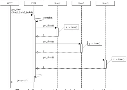
The internal action is used to describe actions of an instance other than sending or re-ceiving a message, e.g. variable assignments or assertion evaluations. Graphically it is a stereotyped note attached to a particular point on an instance as shown in the sequence diagram of Fig 1, for example (the three assignments).
Coregion
A coregion is used to introduce concurrency, e.g. when we do not want to restrict the behaviour of the SUT to one particular ordering. Graphically, it is presented as a self-invocation of the method coregion which thus defines the scope of the coregion con-struct. An activation contained inside a coregion cancels the effect of that coregion. A coregion contained inside an activation has the usual effect. See Fig 1 for an example.
(x+y+z)/3 y get_time() x get_time() get_time (Stub1,Stub2,Stub3)
MTC CUT Stub1 Stub2
coregion Stub3 x := time() z get_time() z := time() y := time()
Figure 1: Coregion used for order independence in multicast 6.3 ¡TeLa! sequence connector diagrams
The features of UML activity diagrams used in sequence connector diagrams are:
• Action states: in ¡TeLa!, either the “action” of an “action state” (we also use the term node) is a sequence diagram name, a dash is used in the case of the empty diagram,
or the state is terminal. Terminal nodes denote verdicts. Empty diagrams are used in loops with exit condition or in consecutive choices, in order to respect UML syntax.
• Transitions: in ¡TeLa!, transitions between action states denote concatenation of the
corresponding sequence diagrams. Concatenation of a terminal state to a sequence diagram denotes termination of that sequence diagram and a verdict being obtained.
• Decisions: in ¡TeLa!, as in UML, the diamond-shape decision syntax is used for both
choice and merge, with only the choice case admitting guards. However, in ¡TeLa!, guards may only be attached to the lines emanating from the diamond shape in a choice (not to the incoming lines). We demand that any guards be annotated with an instance name belonging to a tester instance in existence at the time of the choice (i.e. part of the initial context or created in an earlier event). A choice may lead straight to another choice via an empty sequence diagram. See Figs. 2 and 3 for examples.
• Loops: we allow transitions to form loops. By using an empty sequence diagram,
such loops may commence with a choice, allowing us to model loops with exit con-ditions. See Fig. 2 for an example.
The following features of UML activity diagrams are not used:
• Concurrency (synch states or concurrency expressions): for simplicity, we only
al-low concurrency at the sequence diagram level (via the coregion construct). As for HMSCs, the sequence diagram concatenation mechanism does not imply a synchro-nisation point so any concurrency between events on different instances is not trun-cated at concatenation points.
• Subactivity states: nodes which contain sequence-connector diagrams are disallowed
on the grounds of simplicity.
• Swimlanes, object flow, signal sending & receipt, deferred event: not useful here.
6.3.1. ¡TeLa!-specific control constructs
Sequence-connector loop
Fig 2 shows a loop with a specified termination condition. A loop with an unspecified termination condition is described using a non-deterministic choice in the loop body.
Sequence-connector choice
If no explicit else alternative is given in a sequence-connector diagram choice, an
else alternative leading to a fail state is implicit. The alternatives of sequence connec-tor diagram choices may be unguarded (neither by an explicit guard nor by a subsequent assert internal action), or may involve guards which are not mutually exclusive. In these cases, we say that the choice is non-deterministic and the interpretation is that only one alternative takes place but the criteria for making the choice are not fully specified. As already stated, each guard is annotated with the tester instance which is supposed to evaluate it. This instance is not obliged to be the same on each alternative of the choice. An alternative guarded by g evaluated by I can be rewritten as an unguarded alternative for which the first action on instance I is the internal action assertg. The notion of
ready instance, see Section 7.2, is important in calculating the semantics of a choice. A
local choice is one in which the only ready instance on each alternative is one and the same instance. A test-local choice is either a local choice involving a tester instance or a choice in which only one tester instance is a ready-to-receive instance.
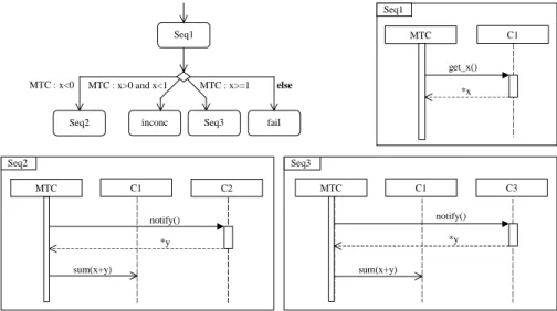
Seq2 MTC CUT get_queue_size() *x Seq1 MTC i := 0 -Seq2 MTC : i < 4 else MTC : x<max_size fail else Seq3 Seq3 MTC i := 1+1 Seq1
Figure 2: A scenario showing a loop and comprising a sequence-connector diagram with one terminal and four non-terminal nodes, together with the corresponding sequence diagrams.
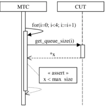
Seq1 MTC C1 get_x() *x Seq2 MTC C1 C2 *y notify() sum(x+y) Seq3 MTC C1 C3 *y notify() sum(x+y) Seq1
Seq2 inconc fail MTC : x<0 MTC : x>=1 else
Seq3 MTC : x>0 and x<1
Figure 3: A scenario showing a choice and comprising a sequence connector diagram with two terminal and three non-terminal nodes, together with the corresponding sequence diagrams.
6.3.2. Implicit choices
An assertion internal action (only allowed on tester instances) occurring as the first action on a tester instance after a choice is considered part of the guard of that choice (and the else alternative is dependent on it). However, when this is not the case, semantically, the assertion still denotes a choice: an implicit choice between an alternative guarded by the assertion annotated by the instance in question and an else transition to a fail state. Similarly a message sent by any SUT instance and received on any tester instance denotes an unguarded choice between the reception of this message and a transition to a fail state. These implicit choices are not made explicit in the canonical form in order to produce more manageable diagrams (though one such choice is made explicit in Fig. 2 for explanatory purposes).
6.4 ¡TeLa! derived constructs
The syntax of the following constructs is chosen to facilitate the use of current tools.
Sequence-diagram loop
This construct is restricted to diagrams involving only two instances to avoid ambiguity3. Graphically, a sequence diagram loop is presented as a self-invocation of the method
for(a;b;c), which thus defines the scope of the loop construct. a, b and c are all expressions in the textual language; a is any internal action occurring immediately be-fore the scope of the loop on the instance, b is an assertion evaluated on each iteration to see if the loop body should be executed, and c is any internal action occurring immedi-ately before the end of the scope of the loop on the instance. for(a;;c) defines a loop with unspecified termination condition. An example is shown in Fig. 4.
MTC CUT
get_queue_size(i) *x for(i=0; i<4; i:=i+1)
« assert » x < max size
Figure 4: Sequence-diagram loop construct; the diagram represents the same behaviour as Fig.2
Sequence-diagram choice
The choice is restricted to one between message receptions or between (guarded) mes-sage emissions. In ¡TeLa!, all choices should be located on tester instances. Graphically,
3
For example, if we add another instance to Fig 4, which messages exchanged between the CUT and this instance are part of the loop body? How do we detect causal chains which start in the loop body and finish outside it (this being contradictory)?
the choice is presented as a self-invocation of the method choice, which thus defines the scope of the choice construct.
Using an extension of the diagram linking mechanism given as a presentation option in [Om01] P.3-113, different sequence diagrams are used to denote the different possible ways another primary sequence diagram can be continued. A different link message is used on this primary diagram for each of the possible continuations. A link message on the primary diagram can be thought of as a goto and one on the continuation diagram (where the behaviour of an alternative is continued) as a label. An example is shown in Fig. 5. It is possible for several gotos to denote a jump to the same label (thus joining different branches immediately after the message involved in the choice). From a tooling point of view, the linking references (the gotos and labels) could be hyperlinks to the corresponding diagram, a mechanism similar to that proposed for Hyper_TSCs [ESG00]. In very simple cases, we allow choices involving a single diagram in which more than one message of each alternative appears, by the use of a block construct. However, as for the sequence diagram loop construct, diagrams containing such choices are restricted to two instances to avoid ambiguity.
A fail verdict is reached if none of the guards evaluate to true in an emission choice or if a message other than those indicated in the choice is received in a reception choice and no explicit else alternative is given.
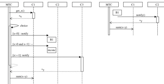
*x [x>0 and x<1] : -MTC C1 C2 C3 choice get_x() B1 [x<0] : notify MTC C1 C2 B1 *y notify() sum(x+y) [x>=1]: notify *y sum(x+y) inconc
Figure 5: A one-tier scenario comprising a choice with one of the alternatives continued on the same diagram and with an explicit verdict + dummy message; the diagram shows the same
behaviour as Fig. 3.
Sequence-diagram guarded message
A single guarded message emission (only allowed on tester instances) can be rewritten as an assertion followed by a message emission and is therefore already dealt with.
6.4.1. Data and the ¡TeLa! textual language
The ¡TeLa! textual language is based on restricted part of the OCL syntax. Some of the main features of interest of this language are the following:
• Structured values: the only structured values used are sequences; contrary to OCL
sequences of sequences are not flattened.
• Operators: a restricted set of the OCL operators is used.
• Variables: they have scope which is global to the test case; they can be assigned to.
• Escape mechanism: a mechanism is provided for escaping to another language (e.g.
an implementation language which the executable test is to be written in). Certain hyphotheses must then be made concerning the effect of such escape points in order to define the ¡TeLa! semantics.
• Arbitrary values: an asterisk is used to denote an arbitrary value. If the tester is
required to be executable (e.g. no constraint resolution at test execution), the asterisk can only be used in messages sent by the SUT. An asterisk followed by a variable name indicates the assignment of this arbitrary value to a variable. Examples can be found in Figs. 2-5.
• Instance names as variables: the names of the instances used in a test case constitute
variables which can be used, for example, as message parameters.
• Guards and assertions: boolean guards can be placed on messages and boolean
assertions can be used as internal actions on an instance.
7 Semantics of ¡TeLa!
7.1 Mapping a ¡TeLa! test case to the UML metamodel
One could conceive of mapping the two-tier structure of a test case by “unfolding” it into a set of metamodel interactions: for each path through the canonical form of the scenario we derive the UML metamodel interaction corresponding to the concatenation of the sequence diagrams encountered in the nodes traversed. However, the use of loops may give rise to infinite-length interactions. Furthermore, the use of loops and branching may give rise to an infinite number of interactions. Therefore we map two-tier scenarios to two-tier metamodel structures.
As stated in Section 4.3, ¡TeLa! sequence diagrams are mapped to the UML metamodel using the maximalist interpretation. The main point of difficulty is in mapping coregions. For example, we must be able to map diagrams in which several messages between the same two instances are in the scope of a coregion on one instance but not on the other. In such cases, the messages are considered ordered (this being the easiest implementation). However, we conserve the information that they were represented as unordered on one of the two instances as an annotation. This annotation will be used in defining the finer semantics discussed in the next section.
7.2 An event-based semantics of dataless ¡TeLa!
Here we briefly sketch how a more formal semantics of ¡TeLa! can be defined as a re-finement of the semantics given by mapping to the metamodel via the maximalist
inter-pretation. This semantics is constructed by first transforming any ¡TeLa! test case into canonical form. This is a two-tier scenario in which all the sequence diagrams are ele-mentary, that is, contain no loops, choices, or guarded messages, though they may con-tain activations, coregions and assertions.
The semantics of a test case is then defined as a set of partial orders (or as a set of pre-fixes of these partial orders if wish to keep them finite), each partial order being the semantics of an elementary sequence diagram. The set of elementary sequence diagrams is obtained from the canonical scenario as follows: for each path through the sequence connector diagram (or finite prefix of such a path), we construct an elementary sequence diagram by concatenating the sequence diagrams encountered in the nodes traversed. This part of the procedure for obtaining the semantics is the same as that discussed above for deriving the set of UML interactions of a scenario by “unfolding” it.
The notion of ready instance, see Section 6.3.1, is defined as follows: let P be the set of partial orders defined by the scenario of one of the alternatives of a choice4. The set of instances which, in at least one5 of the partial orders in P, own an event which has no ancestor in that partial order (minimal events) is called the set of ready instances for that alternative. The ready instances for a terminal state are defined to be those that can reach a verdict (usually only the MTC). The set of ready-to-receive tester instances is defined as the set of tester instances which, in at least one of the partial orders in P, own a re-ceive event which has only one ancestor in that partial order (the corresponding SUT send event).
It then remains to define the semantics of elementary sequence diagrams as a partial order. The basic events of this partial order are synchronous invocation send and receive events, synchronous return send and receive events, asynchronous send and receive events, internal action events and timeout events. First, a graph is derived from the sequence diagram by allowing lifeline splitting at coregions, taking into account the effect of possibly nested activations and coregions. The details are not given here through lack of space. The basic order relations are then defined on this graph between send and receive events of the same message, and between adjacent events on a lifeline. All other order relations are obtained by transitivity.
7.3 Semantics of ¡TeLa! with data
Here we simply outline some of the main considerations for giving a semantics to full ¡TeLa!. In keeping with encapsulation ideas of the object-oriented paradigm, we impose the constraint that each variable of a test case can only be assigned to on one instance of that test case; this instance is then said to be the owner of the variable. We impose the further constraint that any variables contained in guards and assertions must be owned by the evaluating instance. To use a variable owned by another instance in a guard or assertion, its value must first be assigned to a variable belonging to the evaluating in-stance. Removing any ambiguity in the value of variables used in guards and assertions would require the additional constraint that any event involving the use of a variable has
4
Guards/assertions are ignored in these partial orders in the sense that we do not attempt to rule out execution paths which are impossible due to (accumulated) guard conditions.
5
This alternative of the choice may later contain further choices; the ready instances of each of the different alternatives of these choices are not necessarily the same. The difficulty in calculating the ready instances is not discussed here.
an ancestor in the partial order which is an assignment event to that variable, as is done for MSCs [It00]. Unfortunately, however, this last constraint is too strong for a test lan-guage since assign-use paths may traverse the SUT, which must be treated as a black-box. Consequently, the test designer must be aware that a certain amount of ambiguity can still arise concerning the values of a variable at a given use in a test case.
8 Conclusions
In this article we introduce the test description language for component testing, ¡TeLa!. We present the need for such a language and justify our UML-centred approach. We seek to define a language that is integrated as far as possible in UML rather than defining a UML-style syntax for an existing testing language. As our approach is based on UML Interactions, we first clarify the informal semantics of this UML view and discuss the essential features which are currently lacking from the testing standpoint. We then pro-pose new constructs to cater for these needs.
The design of the test description language which we present in this article is carried out in the context of a UML-based component testing project. This language is to be the pivot formalism of a UML testing environment. It will be used as input by the executable test generator and, in work of a more tentative nature, will be produced as output by the test synthesiser. In the first process, we generate executable tests for different platforms from tests specified in ¡TeLa!. In the second, we synthesise tests specified in our UML-based formalism from a test objective, specified in similar formalism, and a UML com-ponent specification. The principles behind this test synthesis have been presented in [JLP98]. The UML specifics of this environment will be encapsulated in a UML Testing Profile. A first version of this profile has been produced and integrated into the Objec-teering UML case tool.
Acknowledgements
The authors would like to thank the other members of the COTE project from France Télécom R&D, Gemplus, Irisa/CNRS, LSR-IMAG and Softeam.
Bibliography
[ESG00] Ekkart, R.; Schieferdecker, I.; Grabowski, J.: Development of an MSC/UML Test Format. In (Eds: J. Grabowski, S. Heymer): Proc. FBT’2000 - Formale
Beschreibungstechniken für verteilte Systeme, Shaker Verlag, Aachen, June 2000. (see http://citeseer.nj.nec.com/rudolph00development.html)
[Et01a] European Telecommunications Standards Institute (ETSI): Methods for Testing and Specification (MTS); The Tree and Tabular Combined Notation version 3; Part 3: TTCN-3: Graphical Presentation Format (GFT).
ETSI Technical Report TR 101 873-3 V1.1.2 (2001-06).
[Et01b] European Telecommunications Standards Institute (ETSI): Methods for Testing and Specification (MTS); Methodological approach to the use of object-orientation in the standards making process.
ETSI Guide EG 201 872 V1.2.1 (2001-06).
[G01] Goeschl, S.: JUnit++ Testing Tool. In Dr. Dobb’s Journal, February 2001 (see also http://www.junit.org/)
[He98] Heymer, S. A non-interleaving semantics for MSCs. In Proc. SAM’98: 1st conference on SDL and MSC. Berlin, June 1998.
[Is92a] ISO/IEC: Information Technology - Open Systems Interconnection - Conformance Testing Methodology and Framework - Part 1: General Concepts, ISO/IEC International Standard 9646. 1992.
[Is92b] ISO/IEC: Information Technology - Open Systems Interconnection - Conformance Testing Methodology and Framework - Part 3: The Tree and Tabular Combined Notation (TTCN). ISO/IEC International Standard 9646. 1992.
[It00] Iternational Telecommunications Union – Telecommunications Sector (ITU-T): Message Sequence Chart (MSC). ITU-T Recommendation Z.120, 2000. [JLP] Jézéquel, J.M.; Le Guennec, A.; Pennaneac'h, F: Validating Distributed Software
Modelled with UML. In Proc. Int. Workshop UML98, Mulhouse, France, Jun 1998. [KL98] Katoen, J.P.; Lambert, L.: Pomsets for Message Sequence Charts. IN Proc. SAM’98:
1st conference on SDL and MSC, Berlin, June 1998.
[Kn99] Knapp, A.: A Formal Semantics for UML Interactions. In Proc. UML’99, LNCS 1723. Springer-Verlag 1999.
[La86] Lamport, L.: On Interprocess Communication. In Distributed Computing 1,2 1986. [LL95] Leue, P.; Ladkin, S.: Interpreting Message Flow Graphs. In Formal Aspects of
Computing, 1995
[MP99] Muscholl, A.; Peled, D.: Message Sequence Graphs and Decision Problems on Mazurkiewicz Traces. In (Wierzbicki, T.; Kutylowski, M.; Pacholski, L. Eds.): Proc. MFCS’99. LNCS 1672. Springer 1999.
[Om01] Object Management Group (OMG): Unified Modelling Language Specification, version 1.4. OMG Draft Standard, February 2001.
(see http://www.omg.org/techprocess/meetings/schedule/UML_1.4_RTF.html) [Ra01] Rational Software: Component Testing with Rational Quality Architect. White paper,
Rational Software 2001.