Specification Guidelines for
Surface Preparation of
Concrete Prior to Repair
by Luc Courard, Benoit Bissonnette, Andrzej Garbacz, Alexander M. Vaysburd, and Kurt F. von Fay
T
o achieve a durable, repaired concrete structure, the specifier of a repair project should require the use of equipment, techniques, and procedures that are appropriate for the project objectives, deterioration mechanism(s), environmental conditions, structuralcircumstances, and other local conditions and limitations that exist for the specific structure or part of the structure.
Success will be dependent on determining the cause and extent of concrete distress or deterioration, establishing realistic repair objectives, and developing a repair strategy to address the problem.1,2 Ultimately, the project team must achieve:
•
The required condition of the substrate regarding cleanliness, roughness, cracking, tensile and compressive strength, chlorides and other aggressive agents, depth of carbonation, moisture content, and temperature;•
Compatibility of the existing concrete and reinforcement with the repair and protection materials and systems, and compatibility between different repair and protection products, including avoiding the risk of creating conditions that may cause acceleration of corrosion;•
The specified characteristics and properties of repair materials and systems and the composite repair system regarding the fulfillment of their purpose to prolong the useful service life of the structure; and•
The required repair application conditions, such as ambient temperature, humidity, wind force, precipitation, and any temporary protection.Concrete surface preparation deals with the various operations needed to fulfill these requirements. This article summarizes the results and outcome of a research project titled “Development of Specifications and Performance Criteria for Surface Preparation Based on Issues Related to Bond Strength.”3 The work was sponsored by the ACI Foundation’s Concrete Research Council, Farmington Hills, MI, and the U.S. Department of the Interior’s Bureau of
Reclamation (USBR), Denver, CO. The research was also supported by Laval University, Québec City, QC, Canada; the University of Liège, Liège, Belgium; and Warsaw University of Technology, Warsaw, Poland.
Concrete Surface Preparation
General considerations
Concrete preparation is the process by which sound, clean, and suitably roughened surfaces are produced in areas to be repaired.4 It includes delineating the repair boundaries by sawcutting; removal of unsound and, if necessary, sound concrete and bond-inhibiting foreign materials from the exposed concrete and reinforcement surfaces; opening the concrete pore structure; and repairing reinforcement damage, if required.5 Concrete must be removed if it is affected by spalling, delamination, or disintegration, or if it is in an area with severe cracking due to active corrosion of reinforcing steel.6
In addition to unsound concrete with reduced mechanical integrity and/or contamination, some sound concrete must also be removed as needed to provide adequate repair geometry, to repair embedded reinforcement, and to allow structural modifications. The effectiveness of various concrete removal techniques may differ for unsound and sound concrete, and a combination of techniques may be necessary. However, the methods used to remove the deteriorated or contaminated concrete and prepare the concrete and
reinforcement to receive the repair material must not weaken the surrounding sound concrete and reinforcement.7
Bond strength of concrete repairs depends on several parameters. It has been shown3 that when substrate-induced damage is prevented or kept below a certain level, tensile bond strength increases with the substrate surface coarseness. Still, one of the most important parameters apparently remains the mechanical integrity of the substrate. In that regard, it must be stressed that impacting tools such as chipping
hammers may significantly damage the surface, and this can completely outweigh the benefits of an increased roughness. When using such equipment, extra steps should be taken during removal of the weakened superficial layer.
Concrete removal
Concrete removal methods are categorized by their type of action: impacting, blasting, cutting, milling, presplitting, and abrading. “Guide to Concrete Repair (ACI 546R-14)”8 describes these categories, lists the respective removal techniques, and provides a summary of information on each. Among the various concrete removal methods, only breakers (chipping hammers and jackhammers) and high-pressure water jets (hydrodemolition) are addressed in the following sections because they are the main options for removing a significant depth of concrete. Most of the other methods are intended to remove the skin concrete and/or to texturize the surface.
Breakers: The most commonly used removal systems,
which generally employ the repeated striking of a concrete surface with a high-energy tool to fracture and spall the concrete. Impacting devices include handheld chipping hammers and large, machinery-mounted hydraulic breakers.
The handheld breakers (Fig. 1) are available in various sizes with different levels of energy and efficiency. Small breakers (15 lb [7 kg]) are commonly specified for partial removal of unsound concrete or concrete around reinforcing steel because they cause little damage to surrounding
concrete. Larger handheld breakers (30 to 90 lb [13 to 40 kg]) are used for complete removal of large volumes of concrete. Care should be exercised when selecting the size of breakers to minimize the damage to existing concrete and its bond to embedded reinforcing steel.
While a variety of cutting tools are used in handheld breakers, the shank end—the end of the tool that is inserted into the tool-retaining mechanism—is common to all. The cutting or working end can vary from a broad spade-like blade to a sharp, well-honed point. Most concrete removal work is done with a pointed tool, although a relatively narrow (3 to 4 in. [75 to 100 mm]) blade-type tool is sometimes used to remove cracked and deteriorated concrete.
The effects of the breaker operation must be monitored to ensure minimal disruption of the surrounding environment by noise, dust, and flying debris. Also, breakers should be operated at less than 45 degrees from the vertical. Removal near the repair boundaries must be completed with spade bits, as gouge bits can damage sound concrete.
High-pressure water jets: This tool type (Fig. 2) employs
a small jet of water driven at high velocities, commonly producing pressures of 10,000 to 45,000 psi (69 to 310 MPa).9 Water jetting may be used as a primary technique for removal of concrete when it is desired to preserve and clean the steel reinforcement for reuse and to minimize damage to the concrete remaining in place (Fig. 3). Water jetting literally disintegrates concrete to sand and gravel-sized pieces, working preferentially on unsound or deteriorated concrete and leaving a rough profile.10 However, care must be taken not to punch through thin slabs or decks. Further, water jetting should not be allowed if there is a possibility that unbonded post-tensioned systems are within the removal zone3 (the only viable method of concrete removal in such a situation is using lightweight chipping hammers).
Two trial areas, one of sound concrete and one of deteriorated concrete, should be used to determine the appropriate water-jetting speed, pressure, and number of
Fig. 1: Pneumatic jackhammer (photo courtesy of Structural Group)
Fig. 2: Principle of action of the high-pressure water-jetting process9
Fig. 3: Concrete and steel reinforcement after high-pressure water jetting
overlapping passes.3 Once properly calibrated, these operating parameters should not be changed unless the concrete changes (for example, if it is found that a harder aggregate has been used in one portion of the structure).
As with sawing operations, the debris and slurry that result from the water-jetting operation must be removed using a low-pressure water stream before the slurry dries and hardens at the surface of the cavity.
The advantages of water jetting include:
•
Fewer workers are required than with other procedures;•
Only weak concrete is removed when water jetting is performed by an experienced operator using appropriate operating parameters;•
It produces well-controlled but rough and irregular cavity surfaces that enhance bonding; and•
It eliminates manual hauling of rubble from the repair area. The disadvantages of water jetting include:•
The finished surfaces are saturated, so repair placement may have to be delayed until the area dries unless the repair material is not moisture-sensitive;•
The fine slurry laitance remaining after the procedure requires careful attention during cleaning;•
A protective shield must be built around the repair area if the patch is next to occupied areas;•
Controlling the depth of removal can be difficult;•
Equipment rental is expensive;•
It can be difficult to obtain a good production rate— performance of water-jetting equipment may be variable; and•
The wastewater and debris must be handled in anenvironmentally acceptable manner, as prescribed by local regulations.
Treatment of exposed reinforcing steel
The most common cause of concrete deterioration is the corrosion of embedded reinforcing steel. Adequate evaluation and treatment will ensure that the repair will not fail
prematurely. The first step is removing deteriorated or chloride-contaminated concrete surrounding the
reinforcement. Sufficient care should be exercised to avoid further damage to the steel. Workers have to be aware of the location of reinforcement, they should use light (13 to 15 lb) chipping hammers to remove the concrete in the vicinity of the reinforcement, and they should take the necessary precaution to avoid vibrating the reinforcement or otherwise causing damage to the bond of reinforcement to concrete adjacent to the repair area.
All unsound concrete should be removed. If reinforcing steel is exposed, then enough concrete must be removed to provide a minimum clear space between the bar and the surrounding concrete of 3/4 or 1/4 in. (19 or 6 mm) larger than the maximum size aggregate in the repair material, whichever is greater.
Additional concrete removal must be carried out along corroded exposed bars until a continuous length of at least 2 in. (50 mm) of bar free from corrosion is exposed. An additional
length of uncorroded reinforcing bar must be exposed if couplers or lap splices are to be used for replacement or supplemental reinforcement. Again, the concrete removal area should have neat vertical faces at the perimeter, and the extent of concrete removal must be agreed upon by the licensed design professional.
Final step in the concrete removal operation
The dynamic loads imposed by removal operations can result in subsurface cracking within the substrate. This damage, typically on the order of 1/8 in. (3 mm) deep, is generally referred to as bruising (Fig. 4). Extensive bruising may result in very low bond strength with the failure plane running entirely through the substrate. This can be evaluated by conducting pulloff tests on the prepared substrate, as described subsequently.11 Bruising can be further identified conclusively and quantified through a petrographic examination of the concrete.12
Bruising can be minimized by exercising care in the removal process and, where possible, by avoiding the use of more detrimental techniques such as scabblers, bush hammers, or large pneumatic hammers (especially hammers equipped with wide chisel tools). Where these tools must be used to increase production and/or reduce costs, the damage can be mitigated by carrying out a final step with a less aggressive method to remove a layer of concrete about 0.10 to 0.20 in. (2 to 5 mm) in depth. This is typically performed with one of the following abrading techniques:
•
Sandblasting—the most commonly used method for bothconcrete and reinforcing steel surface preparation, in which common sand, silica sand, metallic sand, or slag (also known as Black Beauty®) are propelled at high velocity
against the surface to be abraded;
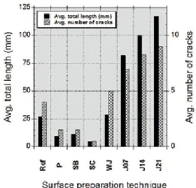
Fig. 4: Average total length and average number of cracks for different surface preparation techniques on a 0.32 m2 concrete surface
(Ref is without preparation; P is polishing; SB is sandblasting; SC is scarification; WJ is high-pressure water jetting; J07 is jackhammering 7 kg (15 lb) + sandblasting; J14 is jackhammering 14 kg (31 lb) + sandblasting; J21 is jackhammering 21 kg (46 lb) + sandblasting)7
•
Shotblasting—in which metal shot is propelled at a highvelocity. In this method, the rebounding shot and pulverized concrete are vacuumed into the shotblasting machine, which separates the shot from the concrete so the shot can be reused; and
•
Waterblasting—suitable for vertical and horizontalsurface preparation, this technique is similar to high-pressure water jetting, except that smaller, typically handheld equipment is used to spray water at pressures between 5000 and 15,000 psi (35 to 105 MPa). For increased efficiency, abrasive particles such as aluminum oxide or garnet can be introduced into the stream.
Conditioning of the surface
Cleanliness: The presence of oil, grease, dust, or laitance
prevents intimate, continuous contact between the materials to be bonded, thus compromising the development of bonding forces in repairs.2 Concrete removal techniques usually yield surfaces with adequate levels of cleanliness. If grease or oil is still present, however, it may be necessary to use (suitable) chemical cleaning agents.
Carbonation: A long delay between surface preparation
and the repair material placement may allow the freshly exposed substrate surface to carbonate. The carbonation depth will be a function of the extent of the delay, the concrete porosity, and the amount of ambient CO2. Until recently, there was very little information on how carbonation will affect bond development of the repair system. Although carbonation products partially fill pores, we have recently completed tests that show that carbonation has little impact on the bond strength of a cement-based material placed on a sound, properly prepared concrete substrate surface. However, we also observed that the detrimental effects of bruising upon repair bond can be worsened if carbonation is allowed to occur prior to repair. Therefore, in unusual situations where a prepared concrete surface has been exposed for extended periods of times, the superficial layer should be removed using one of the aforementioned abrading-type surface preparation techniques.
Moisture content: We have observed that in many
specifications, the required moisture condition of the substrate is generally ill-defined or is addressed without any due consideration to the given substrate characteristics. However, the substrate surface moisture content has a significant influence on the bond between existing concrete and repair material. The standard specification, if any, is to specify the saturated surface dry (SSD) condition of the substrate prior to application of cementitious repair materials. This widespread approach derives from the following rationale: on the one hand, superficial porosity of the concrete substrate to be repaired should allow some penetration of the repair material to promote a strong mechanical bond and, on the other hand, it should not absorb too much of its water, as it may alter the hydration process.
SSD means that the porosity immediately under the surface
is saturated, with no film of liquid water standing on the surface. This condition is typically achieved in practice by soaking the substrate for a while and then allowing the surface to dry out prior to repair material placement, long enough to eliminate water accumulations in the lower points. This does provide an intuitive solution to avoid problems but has never been rigorously defined, measured, or tested. After all, there is no qualitative or quantitative physical meaning of the SSD condition, and there is no strict definition for the degree of saturation, the depth of saturation, or how it is measured.
Nevertheless, there is experimental evidence that SSD is not the optimum moisture condition for bond development in all situations. For example, the influence of the substrate moisture content upon bond strength is illustrated for a polymer-modified repair mortar in Fig. 5.
Overall, for the repair systems considered in the test program, the optimum saturation levels for repair bond strength would lie somewhere between 55 and 90%. It seems that unsaturated pores below the surface can be beneficial. This observation is consistent with the results yielded in one of the very few in-depth experimental studies reported on the subject.13
The nonuniversal character of the optimum moisture condition of concrete prior to repair has been highlighted in a recent study by the USBR.14 For the conditions and materials investigated, it was found that for normal- and higher-strength (about 5000 psi [35 MPa] and higher) concrete elements repaired with portland cement-based materials, prewetting of the substrate is not necessary for optimum bond strength. Conversely, for the repair of lower-strength concrete elements, higher bond strength was obtained with the so-called SSD condition achieved after water ponding for 6 hours.
In any case, it is fundamental to avoid the presence of standing liquid water on the surface.
Bonding agents: The primary reason for using a bonding
agent prior to the placement of a repair material is to enhance the contact between the latter and the existing substrate
Fig. 5: Relationship between mortar bond strength and the concrete substrate saturation level of a polymer-modified repair mortar cast over concrete substrates at various saturation levels, with dry or wet consistency polymer-modified slurry3
profile. In some projects, the quality of the concrete surface preparation for repair has been neglected, based upon the false assumption that a poor surface quality can be compensated for by using a bonding agent. In other cases, bonding agents are being specified and used as a “belt-and-suspenders” measure.
With the technology available today, cement-based repair materials having the rheological characteristics to properly wet the existing concrete substrate can easily be designed, eliminating the need of a bonding agent. Bonding cannot, however, compensate for inadequate surface preparation. Furthermore, a bonding agent may act as a bond breaker when used inappropriately, and the use of a bonding agent may create two potential planes of weakness instead of only one.
Hence, bonding agents are generally not
recommended for repairs and overlays employing cement-based materials. In any case, standing water must be removed prior to the bonding agent application. Moreover, application of a bonding agent requires a meticulous management of time—it is indeed necessary to apply the repair product on the bonding agent “a fresco” to avoid the creation of a second interface.
Quality Control
Evaluation of roughness
Many techniques have been developed for accurately describing surface roughness at various scales. For instance, mechanical and laser lab profilometers allow microroughness (high-frequency waves) characterization, while the
interferometric (optical) method is useful for describing the shape of the surface profile. Nevertheless, investigations made using precise laser and mechanical profilometers have clearly indicated that the surface treatment technique does not have much influence on microroughness. This indicates that only the waviness parameters need to be determined for assessing surface roughness prior to repair.
Because surface preparation essentially influences waviness, the optical method based on the Moiré pattern interferometry, which offers significant advantages in terms of production rate and surface area treatment capability, could be used alone to perform surface roughness characterization. While the method directly yields reliable quantitative data, the equipment available today is not adapted to daily field applications. Nevertheless, with the rapid technological development in that field, suitable optical devices, likely automated, may soon be available. This would allow even more rapid and objective assessment.
Among the techniques available today, the most suitable method for field assessment appears to be the Concrete Surface Profile (CSP) developed by ICRI. The CSP system is easy to use and rapidly yields reliable information, regardless
of the surface orientation. Its use was originally limited to surface profiles with a maximum height (vertical distance between the lowest and the highest point of the profile) of 6 mm, consistent with the type of applications for which it was actually designed—that is, surface treatments such as sealers, coatings, and thin overlays (Fig. 6(a)). With the addition of a tenth plate (no. 10), the CSP characterization range now extends to the medium range of roughness for surface repairs. However, rougher profiles such as those obtained with rotomilling, high-pressure water jetting, or use of a heavy breaker are not yet characterized. It can be seen in Fig. 6(b) that above a detection threshold of the optical device of about 0.15 mm, the profile meso-waviness half-amplitude (Amw) determined by interferometry increases linearly with an
increase in the CSP number.
On-site assessment of the profile can be achieved with the use of the replica putty test method, in accordance with ASTM D7682.16 After being applied against the prepared substrate and cured, the testing putty is removed, providing a negative image of the surface profile, which may be examined (Method A) and/or measured (Method B). The peaks and valleys of the surface can be measured using a customized thickness gauge and the data analyzed to determine the surface profile characteristics.
The sand patch test method (ASTM E96517) is another rapid method that can be used in the field. The average surface texture (macrotexture depth) is determined by measuring the area covered by a known volume of sand or other fine grain material spread uniformly over the surface to be assessed. The most significant limitations include a bounded range of validity (heights of 0.25 to 5 mm can be characterized, so high-amplitude surface profiles are
excluded) and conditions of use (horizontal surfaces only, dry, no wind). Nevertheless, within the range of use, the data it yields show good correlation with surface profile
characterization parameters such as average Amw.15
Fig. 6: ICRI CSP evaluation9: (a) photographs of the original nine replicates,
ordered from 1 to 9; and (b) characterization of original CSP replicates performed by Perez15 using Moiré pattern interferometry, where A
mw is
meso-waviness half-amplitude3
(b) (a)
Evaluation of mechanical strength of the concrete substrate
There are numerous examples of repair and overlay projects where the specified bond strength is greater than that of the concrete substrate. Clearly, it is pointless to expect the bond value to be greater than (or even equal to) the tensile strength of the substrate concrete. Many specified testing criteria for bond strength of completed overlays and surface repairs are based on documented recommendations from organizations such as ACI, ICRI, and RILEM and are seldom based on considerations related to the strength of the given concrete to be repaired. In cases when such criteria are not being met based on the tensile pulloff test results of the completed repair or overlay, it is very difficult to establish what went wrong—surface preparation, repair material quality, workmanship, environmental conditions, or a combination of some of these. The benchmarks for the bond criteria are also often taken from the repair materials data sheets and relate to laboratory tests. The expectations to meet these benchmarks at the jobsite, often under difficult working conditions, can be unrealistic. Therefore, sound engineering judgment is necessary. The specifications for a repair project must not be blindly copied from other specifications or a material manufacturer’s data sheet because this may result in situations where it is not physically possible to achieve compliance with the specified criteria. Thus, more consideration needs to be given to the requirements of the project in defining the specifications. To allow the specifier to establish realistic bond strength requirements and test criteria, the condition evaluation should include tensile strength testing of existing concrete.
To provide assurance that the surface preparation procedures have been performed as specified, the tensile pulloff tests should be performed on the prepared surface prior to repair application.11,18 The pulloff test should be done in accordance with the applicable provisions of ICRI Guideline No. 210.3R-2013.19
In cases where the tensile strength of the prepared substrate significantly deviates from the tensile strength of the existing concrete documented in the condition evaluation report, the data should be analyzed by the licensed design professional. Additional surface treatments may be necessary.
Evaluation of reinforcing steel
Exposed reinforcement should be examined carefully to make sure it is free of loose concrete, rust, oil, and other contaminants. Where reinforcing steel bars show signs of deterioration due to corrosion or mechanical causes, the percentage of section loss can be assessed in accordance with the method described in ACI 364.14T-17.20
Evaluation of concrete surface cleanliness
Prior to repair, it is essential to make sure that the concrete surface is free of contaminants, dust, laitance, fragments of concrete, or a bruised concrete layer. In the wake of the newly
developed ICRI Concrete Surface Repair Technician (CSRT) certification program, a TechNote is being developed by ACI Committee 364, Rehabilitation, to provide guidance on how to carry out a cleanliness evaluation adequately as part of a rigorous quality control program for repair works.
Evaluation of moisture
In-place evaluation of the moisture content of concrete remains a challenge. ICRI has recently developed a Concrete Slab Moisture Program for training and certification of personnel involved in the evaluation of the moisture condition in concrete slabs prior to flooring. The program covers five ASTM International test methods, among which ASTM F217021 and F265922 cover in-place evaluation of concrete substrates prior to repair.23,24
With the availability today of simple, affordable embedded relative humidity probes, ASTM F2170 can be used to reliably monitor relative humidity within the concrete cover (depths of 1 to 2 in.). It is not suited, however, to make rapid measurements on multiple areas of an element to be evaluated.
Used in accordance with ASTM F2659, electrical
impedance devices can be implemented to determine when the concrete substrate surface has dried out sufficiently for concrete placement after prewetting. Obviously, such meters have precision limitations and require some calibration, but they are well suited for field testing, allowing the performance of multiple measurements in a short period of time without much effort.
Evaluation of bond
The pulloff test is a convenient method for evaluating both the mechanical integrity of the concrete surface prior to repair and the repair tensile bond strength.2,25-27 A reliable evaluation of these characteristics can be obtained, provided that a minimum number of tests are performed with adequate equipment. The potential bias due to testing misalignment, below average naked-eye detection capability, was assessed to reach up to approximately 15%.28 However, this bias can only affect the pulloff strength evaluation on the conservative side.
ICRI Guideline No. 210.3R-201319 arguably provides the most comprehensive technical guidance with regard to the specification and evaluation of bond for concrete surface materials. The document makes no recommendation for a universal acceptance value. Depending on the project, required bond strength values will typically range from 0.7 to 1.7 MPa (100 to 250 psi) and should not exceed the existing concrete tensile strength. Whenever possible, the
implementation of field trials is desirable. According to the ICRI Guideline,19 for all modes of failure, acceptance of pulloff test results should be based upon the following criteria:
•
Where field trials (mockups) are carried out:◦
Average pulloff strength of the specimens is above the required pulloff strength (90% of average field trial test value); and◦
No specimen test result is below 75% of the average trial specimen test value.•
Where field trials (mockups) are not carried out:◦
Average pulloff strength of the specimens is above the required pulloff strength; and◦
No specimen tests below 75% of the required strength. With a provision allowing single test values reaching 75% of the specified strength, the quality assurance procedure implicitly takes care of the variability of the test associated with misalignment, which was found in the research work carried out by some of the authors24 to reduce the recorded bond strength by up to 15% within a reasonable visual detection limit (±4 degrees).It is important to keep in mind that bond strength between a repair or overlay material and a concrete substrate is in fact a subtle property or, more accurately, characteristic to specify. Ultimately, the key requirement for a successful repair is adequate bond between the repair and existing substrate, which will keep its integrity throughout its service life. At the present time, practical answers to the problems of bond may depend only on short-term bond testing rather than on long-term performance. Bond strength achieved initially is only an indication of performance with the specified parameters. There is no well-defined relationship between
initial bond strength and the lasting interfacial bond in a repair system. Longevity of the bond is influenced by many factors, including substrate surface preparation and texture, relative volume changes of repair material, mass transport, service conditions, and quality and condition of the underlying concrete. To maximize bond quality and durability, proper consideration must be given to all repair compatibility requirements applicable in each situation.2,29,30
Conclusions
The recommendations issued herein generally ensure satisfactory results provided adequate quality control is implemented. It must be emphasized that results of the research project discussed in the article, as well as other reported work on the subject, are primarily dealing with “short-term” bond strength considerations, not with the mechanisms and issues related to long-term bond behavior and durability. The short-term bond strength typically specified and evaluated can be used as an indication of the quality of materials and workmanship (that is, concrete surface preparation for repair, material selection, application, and curing). Long-term bond strength, however, is usually influenced by various other factors, among them
environmental, loading, and fatigue conditions. Therefore, it is
Welcome Reception: Tuesday, August 25, 5:00 pm – 7:00 pm
SDC Technology Sessions: Wednesday, August 26, 8:00 am – 5:00 pm | Thursday, August 27, 8:00 am – 12:00 pm
Visit: www.acifoundation.org/technology/forums
Follow us:
SDC Technology Forum 48 • REGISTRATION IS OPEN
desirable to pursue research efforts on those factors affecting long-term bond strength in concrete repair and overlay systems, notably the surface preparation parameters and characteristics. Ultimately, everything comes down to the overall compatibility between the repair system and the existing concrete with respect to deformations, permeability, chemical reactivity, and electrochemical behavior.
Development of comprehensive guidelines addressing compatibility issues—with special emphasis on the factors related to dimensional compatibility—is needed for repair and rehabilitation to evolve as an engineering discipline.
Acknowledgments
The authors are grateful to the ACI Foundation Concrete Research Council and the U.S. Bureau of Reclamation, which provided financial support to this study as part of an international research project titled “Development of Specifications and Performance Criteria for Surface Preparation Based on Issues Related to Bond Strength.” Support was also provided by the Government of Poland (MNiSW), Wallonia-Brussels International (Belgium), and the Government of Québec (Canada) through bilateral scientific cooperation programs.
References
1. RILEM Technical Committee 193-RLS, Bonded Cement-Based
Material Overlays for the Repair, the Lining or the Strengthening of Slabs and Pavements, B. Bissonnette, L. Courard, D.W. Fowler, and J.-L.
Granju, eds., Springer, 2011, 175 pp.
2. Bissonnette, B.; Courard, L.: and Garbacz, A., Concrete Surface
Engineering, CRC Press, 2015, 272 pp.
3. Bissonnette, B.; Courard, L.; Garbacz, A.; Vaysburd, A.M; and von Fay, K.F., “Development of Specifications and Performance Criteria for Surface Preparation Based on Issues Related to Bond Strength,” Final
Report ST 2017-2886-1, Bureau of Reclamation, U.S. Department of the
Interior, Denver, CO, 2017, 190 pp.
4. Courard, L.; Michel, F.; Schwall, D.; Van der Wielen, A.; Garbacz, A.; Piotrowski, T.; Perez, F.; and Bissonnette, B., “Surfology: Concrete Substrate Evaluation Prior to Repair,” Materials Characterization IV,
Computational Methods and Experiments, A.A. Mammoli and C.A.
Brebbia, eds., Wessex Institute of Technology Press, 2009, pp. 407-416. 5. Courard, L.; Treviño, M.; and Bissonnette, B., “Condition Evaluation of the Existing Structure Prior to Overlay,” Bonded
Cement-Based Material Overlays for the Repair, the Lining or the Strengthening of Slabs or Pavements, RILEM Report of TC 193-RLS, 2011, pp. 17-50.
6. Vaysburd, A.M., and Emmons, P.H., “How to Make Today’s Repairs Durable for Tomorrow—Corrosion Protection in Concrete Repair,” Construction and Building Materials, V. 14, No. 4, June 2000, pp. 189-197.
7. Bissonnette, B.; Courard, L.; Vaysburd, A.M.; and Bélair, N., “Concrete Removal Techniques,” Concrete International, V. 28, No. 12, Dec. 2006. pp. 49-55.
8. ACI Committee 546, “Guide to Concrete Repair (ACI 546R-14),” American Concrete Institute, Farmington Hills, MI, 2014, 70 pp.
9. ICRI Guideline No. 310.2R-2013, “Selecting and Specifying Concrete Surface Preparation for Sealers, Coatings, Polymer Overlays, and Concrete Repair,” International Concrete Repair Institute, St. Paul, MN, 2013, 48 pp.
10. Strömdahl, C., “The History of Hydro Demolition,” Concrete
Engineering International, V. 4, No. 8, 2000, pp. 32-35.
11. Courard, L., and Bissonnette, B., “Pull Off Test for the Evaluation of the Superficial Cohesion of Concrete Substrates in Repair Works: Analysis of the Test Parameters,” Materials and Structures, V. 37, No. 5, June 2004, pp. 342-350. (in French)
12. Garbacz, A.; Courard, L.; and Bissonnette, B., “A Surface Engineering Approach Applicable to Concrete Repair Engineering,”
Bulletin of the Polish Academy of Sciences (Technical Sciences), V. 61,
No. 1, Mar. 2013, pp. 73-84.
13. Pigeon, M., and Saucier, F., “Durability of Repaired Concrete Structures,” Advances in Concrete Technology, V.M. Malhotra, ed., 1992, pp. 741-774.
14. Vaysburd, A.M.; Bissonnette, B.; Thomassin, M.; von Fay, K.F.; Harrell, S.J.; and Robertson, B., “Concrete Substrate Moisture Requirements for Effective Concrete Repairs,” Final Report
ST-2016-2886-0, Bureau of Reclamation, U.S. Department of the Interior, Denver,
CO, 2016, 40 pp.
15. Perez, F.; Bissonnette, B.; and Courard, L., “Combination of Mechanical and Optical Profilometry Techniques for Concrete Surface Roughness Characterization,” Magazine of Concrete Research, V. 61, No. 6, Aug. 2009, pp. 389-400.
16. ASTM D7682-17, “Standard Test Method for Replication and Measurement of Concrete Surface Profiles Using Replica Putty,” ASTM International, West Conshohocken, PA, 2017, 4 pp.
17. ASTM E965-15 (Reapproved 2019), “Standard Test Method for Measuring Pavement Macrotexture Depth Using a Volumetric Technique,” ASTM International, West Conshohocken, PA, 2015, 4 pp.
18. Bungey, J.H., and Soutsos, M.N., “Reliability of Partially-Destructive Tests to Assess the Strength of Concrete on Site,”
Construction and Building Materials, V. 15, No. 2-3, Mar.-Apr. 2001,
pp. 81-92.
19. ICRI Guideline No. 210.3R-2013, “Using In-Situ Tensile Pulloff Created by SmartBrief in partnership with ACI, Concrete
SmartBrief provides a daily e-mail snapshot of the concrete industry with news from leading global sources. Summaries of what matters to you, written by expert editors, to save you time and keep you informed and prepared.
Welcome to Concrete SmartBrief; sign up at:
Sign up for Concrete
www.smartbrief.com/ACI
The smart way to stay on top of
concrete industry news.
Luc Courard is head of the Department of Architecture, Geology,
Environment, and Constructions at the University of Liège, Liège, Belgium. He is currently overseeing various multilateral scientific initiatives, notably in Argentina, Burkina Faso, China, Congo, Madagascar, Romania, and Vietnam. He is coauthor of the book Concrete Surface Engineering (2015). He received his PhD from the University of Liège and was awarded the title of Honorary Professor by the Warsaw University of Technology.
Benoit Bissonnette, FACI, is a Professor in the Department of
Civil Engineering at Laval University, Québec City, Canada, and member of the Research Center on Concrete Infrastructure (CRIB). He is Chair of ACI Committee 364, Rehabilitation, and a member of ACI Committee 223, Shrinkage-Compensating Concrete, and the TAC Repair and Rehabilitation Committee. He is coauthor of the book Concrete Surface Engineering (2015). He received his PhD from Laval University and is a licensed professional engineer in Québec.
Andrzej Garbacz is Dean of the Faculty of Civil Engineering
at Warsaw University of Technology, Warsaw, Poland. He is a member of RILEM Committees TC 193-RLS and TC 184-IFE. He is also a member of the Polish Academy of Sciences and Chairman of the Scientific Council of the Building Research Institute (ITB). He is coauthor of the book Concrete Surface Engineering (2015). In 2005, he was awarded the title of Senior Member by RILEM. He received his PhD from the Warsaw University of Technology.
Alexander M. Vaysburd is Principal of Vaycon Consulting, West
Palm Beach, FL. He is a consulting member of ACI Committees 213, Lightweight Aggregate and Concrete; 364, Rehabilitation; and 365, Service Life Prediction. He was awarded the 1996 ACI Wason Medal for Most Meritorious Paper and the 2000 ACI Cedric Wilson Award for his significant contributions to the concrete industry. He received his PhD from ZNEEP Selstroi, Russia.
Kurt F. von Fay is a retired Civil Engineer from the Bureau of
Reclamation’s Technical Service Center, Denver, CO. He has over 30 years of experience in concrete materials, mixture proportioning investigations, concrete maintenance and repair, and chemical grouting, and he recently completed the second edition of the Reclamation’s Guide to Concrete Repair. He received his engineering degree from the University of Colorado and his MBA from the University of Denver, Denver, CO. Tests to Evaluate Bond of Concrete Surface
Materials,” International Concrete Repair Institute, St. Paul, MN, 2013, 20 pp.
20. ACI Committee 364, “Section Loss Determination of Damaged or Corroded Reinforcing Steel Bars (ACI 364.14T17),” American Concrete Institute, Farmington Hills, MI, 2017, 4 pp.
21. ASTM F2170-19, “Standard Test Method for Determining Relative Humidity in Concrete Floor Slabs Using in situ Probes,” ASTM International, West Conshohocken, PA, 2019, 7 pp.
22. ASTM F2659-10 (Reapproved 2015), “Standard Guide for Preliminary Evaluation of Comparative Moisture Condition of Concrete, Gypsum Cement and Other Floor Slabs and Screeds Using a Non-Destructive Electronic Moisture Meter,” ASTM International, West Conshohocken, PA, 2010, 6 pp.
23. Vaysburd, A.M.; Bissonnette, B.; and von Fay, K.F., “Moisture Condition Testing of Concrete: A Review of Methods,” U.S. Bureau of Reclamation, Denver, CO, 2009, 52 pp.
24. Bissonnette, B.; Vaysburd, A.M.; and von Fay, K F., “Moisture Content Requirements for Repair, Part 1: Concrete Repair Testing,”
Report No. MERL-2013-63, Bureau of
Reclamation, U.S. Department of the Interior, Denver, CO, 2014, 45 pp.
25. CAN/CSA-A23.2-6B14, “Method of Test to Determine Adhesion by Tensile Load,” CSA Group, Toronto, ON, Canada, 2014.
26. EN 1542:1999, “Products and Systems for the Protection and Repair of Concrete Structures – Test Methods – Measurement of Bond Strength by Pull-Off,” European Committee for Standardization, Brussels, Belgium, 1999, 10 pp.
27. BS 1881-207:1992, “Testing Concrete. Recommendations for the Assessment of Concrete Strength by Near-to-Surface Tests,” British Standard Institution, UK, 1992, 18 pp. 28. Courard, L.; Bissonnette, B.; Garbacz, A.; Vaysburd, A.M.; von Fay, K.F.; Moczulski, G.; and Morency, M., “Effect of Misalignment on Pulloff Test Results: Numerical and Experimental Assessments,” ACI Materials
Journal, V. 111, No. 2, Mar.-Apr. 2014,
pp. 153-162.
29. Vaysburd, A.M.; Bissonnette, B.; and von Fay, K.F., “The Challenges of Achieving Compatibility in Concrete Repair,” Concrete
International, V. 39, No. 12, Dec. 2017, pp. 37-43.
30. Courard, L.; Bissonnette, B.; and
Garbacz, A., “Fundamental Approach to the Concept of Concrete Repair Compatibility,”
Concrete Repair, Rehabilitation and Retrofitting IV, F. Dehn, H.-D. Beushausen, M.G.
Alexander, and P. Moyo, eds., CRC Press, 2015, p. 164.