HAL Id: tel-01638202
https://tel.archives-ouvertes.fr/tel-01638202
Submitted on 20 Nov 2017
HAL is a multi-disciplinary open access
archive for the deposit and dissemination of sci-entific research documents, whether they are pub-lished or not. The documents may come from teaching and research institutions in France or abroad, or from public or private research centers.
L’archive ouverte pluridisciplinaire HAL, est destinée au dépôt et à la diffusion de documents scientifiques de niveau recherche, publiés ou non, émanant des établissements d’enseignement et de recherche français ou étrangers, des laboratoires publics ou privés.
Combined theoretical and experimental study of the
ionic conduction in oxide-carbonate composite materials
as electrolytes for solid oxide fuel cells (SOFC)
Chiara Ricca
To cite this version:
Chiara Ricca. Combined theoretical and experimental study of the ionic conduction in oxide-carbonate composite materials as electrolytes for solid oxide fuel cells (SOFC). Chemical Physics [physics.chem-ph]. Université Pierre et Marie Curie - Paris VI, 2016. English. �NNT : 2016PA066623�. �tel-01638202�
THESE DE DOCTORAT DE
L’UNIVERSITE PIERRE ET MARIE CURIE
Ecole Doctorale De Chimie Analytique et Physique de Paris Centre
(ED 388)
Combined theoretical and experimental study of the ionic
conduction in oxide-‐carbonate composite materials as
electrolytes for solid oxide fuel cells (SOFC)
Présentée par
Chiara Ricca
Pour obtenir le grade de
DOCTEUR DE L’UNIVERSITE PIERRE ET MARIE CURIE
Soutenue le 18/11/2016, devant le jury composé par :
M. Philippe D’Arco Professeur –UPMC Président
M. David Loffreda Directeur de Recherche – ENS Lyon Rapporteur
M. Antonino Martorana Professeur –Università degli Studi di Palermo Rapporteur
M. Jean François Halet Directeur de Recherche –Université de Rennes 1 Examinateur
Mme Caroline Pirovano Maître de Conférences–ENSC Lille Examinatrice
M. Frédéric Labat Maître de Conférences –IRCP Chimie Paris-‐Tech Invité
M. Carlo Adamo Professeur –IRCP Chimie Paris-‐Tech Directeur de thèse
Remerciements
En tout premier lieu, je souhaite adresser mes remerciements `a mon directeur de th`ese, Carlo Adamo, pour m’avoir donn´e la possibilit´e de travailler `a l’IRCP Chimie Paris-Tech et pour la supervision de mon travail. Je remercie ´egalement ma co-directrice, Armelle Ringued´e, pour m’avoir transmis une partie de son exp´erience et pour sa disponibilit´e au quotidien.
Je remercie tout particuli`erement Fr´ed´eric Labat pour avoir encadr´e la partie th´eorique de cette th`ese, our toutes les connaissances qu’il a su me transmettre, pour le grand l’int´erˆet port´e `a mon travail, pour l’aide pr´ecieuse qu’il m’a apport´e dans toutes les d´emarches ad-ministratives, pour les conseils des plus avis´es, ainsi que pour son soutien lors des moments difficiles et particuli`erement pendant la derni`ere ann´ee.
Je remercie ´egalement Michel Cassir de m’avoir accueillie au sein de l’´equipe Interface, ´Electrochimie, ´Energie (I2E) et pour avoir pris le temps de partager avec moi de assionnantes discussions sur les sciences, la culture et la politique italiennes. Merci aussi `a Ilaria pour l’accueil au sein de l’´equipe de Chimie Th´eorique et Mod´elisation et pour le soutien durant les moments les plus durs de ces trois ann´ees et pour ses conseils toujours avis´ees.
Je tiens de mˆeme `a remercier Alistar pour l’aide pr´ecieuse et ses r´eponses quant `a mes doutes et autres probl`emes. Mes remerciements s’adressent ´egalement `a Andrey et Val´erie pour l’aide indispensable qu’ils mont apport´e durant mes travaux exp´erimentaux.
Je souhaite exprimer toute ma reconnaissance envers MM. David Loffreda et Antonino Martorana pour avoir accept´e d’ˆetre rapporteurs de ce travail, ainsi qu’`a M. Philippe D’Arco, M. Jean-Franc¸ois Halet et Mme Caroline Pirovano pour leur participation `a mon jury de th`ese.
Je tiens `a remercier toutes les personnes que j’ai rencontr´e dans les deux ´equipes tout au long de ces ann´ees: Stefania C., Romain, Valentino, ´Eric, Vinca, Alexandra, Marika, Domenico, Manel, Arturo, Oumaima, Indira, Luca et en particulier Marta, Liam, Umberto et Marianna pour les discussions et pour tout le temps que nous avons pass´e ensemble en dehors du laboratoire.
Un remerciement tr`es sp´ecial `a Stefania. Son amiti´e, son aide, ses conseils et son ´eternel soutien sont inh´erent `a l’aboutissement de ce projet. Merci surtout de m’avoir toujours en-courag´ee `a ne jamais abandonner et pour avoir ´enorm´eent contribu´e `a faire en sorte que je puisse me sentir chez moi.
Je suis tout particuli`erement reconnaissante envers mes parents, car c’est grˆace `a eux si aujourd’hui je peux dire avoir v´ecu cette magnifique exp´erience parisienne, envers ma soeur pour m’avoir aid´ee `a transformer mon petit studio en un lieu plus confortable, et bien entendu envers mon fr`ere pour ses conseils. Merci `a Mario pour avoir tenu bon malgr´e la distance et toutes les difficult´es rencontr´ees pendant ces trois ann´ees.
Enfin, un grand merci `a Edda et Andreea qui n’ont jamais cess´e de me soutenir malgr´e les nombreux kilom`etres qui nous s´eparent.
Acknowledgments
First, I would like to thank Prof. Carlo Adamo who has given me the opportunity to work at IRCP Chimie Paris-Tech and for supervising my work. I would also like to thank my co-supervisor Armelle Ringued´e for sharing with me her knowledge in the field of fuel cells and for her kindness.
I would like to particularly acknowledge Fr´ed´eric for guiding me through the theoretical part of this thesis, for all the knowledge he has shared with me, the interest he has shown in my work, and the help, advice and support he has provided especially during the most difficult moments in the last year of my PhD.
I would also like to thank Michel Cassir for welcoming me to the I2E team and for the interesting discussions about science or Italian culture and politics, as well as Ilaria for welcoming me to the CTM group and for her advice and support during these three years.
Thanks to Alistar for the help and discussions every time I had doubts or problems and to Andrey and Val´erie for helping me with the experimental part of this work.
I would like to acknowledge Mr. David Loffreda, Mr. Antonino Martorana, Mr. Philippe D’Arco, Mr. Jean Franc¸ois Halet and Mrs. Caroline Pirovano for agreeing to be part of my thesis committee.
Thanks to all the people I have met during my PhD in the I2E and CTM groups: Ste-fania C., Romain, Valentino, Eric, Vinca, Alexandra, Federica, Domenico, Manel, Arturo, Oumaima, Indira, and Luca. In particular, thanks to Marta, Liam, Umberto, and Marianna for the discussions and the time spent together.
I would especially like to thank Stefania for her friendship, help, advice and support. Thanks for having always encouraged me to never give up and for having made it possible for me to feel at home.
Thanks to my parents, since it is thanks to of them that I lived this wonderful experience in Paris, to my sister and brother for their support and advice, and to Mario for holding on despite the distance and all the difficulties.
Contents
Abbreviations xii
Defect Notation xiv
1 General Context and Objectives 1
1.1 The role of fuel cells in the current energetic context . . . 1
1.2 Fuel Cells . . . 5
1.2.1 Functioning Principles and Classification . . . 5
1.2.2 Fuels for Electrochemical Cells . . . 7
1.2.3 SOFC . . . 8
1.2.4 The problem of lowering SOFC operating temperature . . . 12
1.2.5 MCFCs and SOFCs . . . 14
1.3 Composite Materials . . . 17
1.3.1 Space Charge Layer Theory . . . 18
1.3.2 Carbonate/oxide electrolytes . . . 19
1.3.3 Conduction Mechanisms in oxide-carbonate electrolytes . . . 27
1.4 Research strategy: a combined experimental and theoretical approach . . . 32
2 Theoretical and Experimental Methods 37 2.1 Introduction . . . 37
2.2 Theoretical Background . . . 37
2.2.1 The Shr¨odinger Equation . . . 37
2.2.2 The Hartree-Fock (HF) Theory . . . 39
2.2.3 Density Functional Theory (DFT) . . . 43
2.2.4 Modelling of crystalline systems . . . 50
2.2.5 Ab initio Molecular Dynamics (MD) . . . 53
2.3 Experimental Background . . . 59
2.3.1 Electrochemical Impedance Spectroscopy (EIS) . . . 59
3 Experimental Results 63 3.1 Introduction . . . 63
3.2 Preparation of the composite materials . . . 64
3.2.1 Thermal analysis . . . 65
3.2.2 XRD characterization . . . 66
CONTENTS CONTENTS
3.3 Electrochemical characterisation . . . 66
3.3.1 EIS experimental details . . . 66
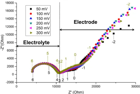
3.3.2 Electrochemical behaviour of oxide-carbonate composites . . . 71
3.4 TGA and DTA analyses . . . 86
3.5 Premilinary XRD characterization . . . 91
3.5.1 YSZ-(Li,K)2CO3 composite . . . 91
3.5.2 YSZ-(Li,Na)2CO3 composite . . . 93
3.5.3 TiO2-(Li,K)2CO3composite . . . 93
3.6 IR and Raman characterization . . . 96
3.6.1 Infra-red spectra . . . 96
3.6.2 Raman spectra . . . 99
3.7 Conclusions . . . 102
4 Modeling of the oxide phase: YSZ 103 4.1 Introduction . . . 103 4.2 Computational Details . . . 106 4.3 ZrO2bulk . . . 107 4.3.1 Structure . . . 108 4.3.2 Relative Stability . . . 109 4.3.3 Electronic properties . . . 113 4.4 ZrO2Surfaces . . . 119 4.4.1 Surface Energetics . . . 120 4.4.2 Surface Geometries . . . 122
4.4.3 Surface Electronic Properties . . . 125
4.5 Reducibility properties of the (111) of c-ZrO2surface . . . 126
4.5.1 Formation Energy and Structural Rearrangements . . . 128
4.5.2 Electronic structure of oxygen vacancy . . . 131
4.6 Y2O3-doped (111) surface . . . 134
4.6.1 Stability and Structural Rearrangements in YSZ-(111) surface . . . 134
4.6.2 Electronic structure of YSZ-(111) surface . . . 137
4.7 Conclusions . . . 139
5 Modeling of the carbonate phase 141 5.1 Introduction . . . 141
5.2 Computational Details . . . 144
5.2.1 DFT Calculations . . . 144
5.2.2 Calculation of the dielectric constant . . . 146
5.2.3 Calculations in presence of an external electric field . . . 147
5.3 LiNaCO3and LiKCO3 bulk . . . 147
5.3.1 Structure optimization and relative stability . . . 148
5.3.2 IR and Raman Spectra . . . 151
5.3.3 Electronic Properties . . . 153
5.4 LiNaCO3and LiKCO3 Surfaces . . . 157
5.4.1 Reconstruction of the dipolar (001) LiNaCO3 surface . . . 157
CONTENTS CONTENTS
5.4.2 Non polar (110) LiNaCO3 surface . . . 162
5.4.3 (001) and (110) LiKCO3 surfaces . . . 163
5.5 Li transport at the LiKCO3-(001) surface . . . 163
5.5.1 Defect Formation . . . 164
5.5.2 Diffusion mechanism . . . 172
5.6 Conclusions . . . 177
6 DFT simulation of YSZ-LiKCO3 composite 179 6.1 Introduction . . . 179
6.2 Computational Details . . . 181
6.2.1 DFT calculations . . . 181
6.2.2 MD calculations . . . 183
6.3 DFT investigation of the stability and electronic properties of YSZ-LiKCO3 183 6.3.1 Building the YSZ-LiKCO3interface model . . . 183
6.3.2 YSZ-LiKCO3 structure and stability . . . 185
6.3.3 IR and Raman Spectra . . . 189
6.3.4 YSZ-LiKCO3 electronic properties . . . 193
6.4 DFT Study of Conduction Mechanisms . . . 196
6.4.1 Li transport . . . 197
6.4.2 Oxygen transport . . . 208
6.4.3 Proton transport . . . 216
6.5 Preliminary Results of the MD Simulations . . . 222
6.6 Conclusions . . . 224
7 DFT simulation of TiO2-LiKCO3 materials 227 7.1 Introduction . . . 227
7.2 Computational Details and Models . . . 228
7.3 Structure and Stability of the TiO2-LiKCO3interface . . . 230
7.4 TiO2-LiKCO3 Electronic Properties . . . 233
7.5 Li intercalation at the TiO2-LiKCO3interface . . . 236
7.6 Conclusions . . . 242
8 Conclusions and Perspectives 245
Abbreviations
AFC Alkaline fuel cells APU Auxiliary Power Unit BCCF BaxCa1 xCoyFe1 yO3BSCF Ba0.5Sr0.5Co0.8Fe0.2O3
BSSE Basis set superimposition error BSY Yttium-doped barium zirconate CB Conduction band
CHP combined heat and power
COP21 21th Conference of Parties
DFT Density Functional Theory DTA Differential Thermal Analysis EELS Electron energy loss spectroscopy EIS Electrochemical impedance spectroscopy EU European Union
FC Fuel Cells
GDC Gadolinium Doped Ceria GGA General gradient approximation GHG Greenhouse-gas
GTF Gaussian type function KS Kohn and Sham
HF Hartree Fock
HRTEM High resolution transmission electron microscopy HT high temperature
IBZ Irreducible Brillouin zone IT intermediate temperature
CONTENTS CONTENTS LDA Locan density approximation
LSCF LaxSr1 xCoyFe1 yO3
LSCM La0.75Sr0.25Cr0.5Mn0.5O3
LSGM Lanthanum strontium magnesium gallate LSM lanthanum strontium manganite
LT low temperature
MCFC Molten carbonate fuel cells MD Molecular Dynamics
MS Mass Spectrometry MSE Mean Signed Error MUE Mean Unsigned Error NEB Nudget Elastic Band NVE Microcanonical ensemble NVT Canonical ensemble
NVP isothermal-isobaric ensemble ORR Oxygen reduction reaction PAFC Phosphoric acid fuel cells PCFC Protonic ceramic fuel cells PAW Projector Augmented Wave
PEMFC Proton exchange membrane fuel cells PSZ Partially-stabilized zirconia
PW Plane Wave
SCF Self Consistent Field SDC Samarium Doped Ceria ScSZ Scandia-stabilized zirconia SEM Scanning electron microscopy SCFC Single Component Fuel Cells
CONTENTS CONTENTS SOFC Solid Oxide Fuel Cells
STF Slater Type Function
TGA Thermogravimetric Analysis TZP Yttria-doped tetragonal zirconia VB Valence band
VUV vacuum ultraviolet spectroscopy XRD X-ray diffraction
YSZ Yttria-stabilized zirconia ZPE Zero point energy
Defect Notation
VXO Neutral O vacancy
V••
O Doubly positively charged O vacancy
VX
LiNeutral Li vacancy
V0
LiNegatively charged Li vacancy
LiX
i Neutral interstitial Li atom
Li•
i Positively charged interstitial Li ion
Chapter 1
General Context and Objectives
Humanity stands ... before a great problem of finding new raw materials and new sources of energy
that shall never become exhausted.
In the meantime we must not waste what we have,
but must leave as much as possible for coming generations. Svante Arrhenius
Chemistry in Modern Life (1925)
1.1 The role of fuel cells in the current energetic context
The 21th Conference of Parties (COP21) held in Paris in December 2015 represented a
ma-jor milestone in efforts to fight the climate change, one of the most important and difficult challenges that our generation and the next ones have to face. An historical agreement has been indeed signed by 195 countries worlwide. It represents the first-ever universal, legally binding global climate deal, setting out the common intent to limit the global warming well below the 2 C.1This 2 C scenario offers a vision of a sustainable energy system of reduced
Greenhouse-gas (GHG) and carbon dioxide (CO2) emissions.2 The efficient production of
energy is then a fundamental of the modern world.
Energy production and use account for about two-thirds of the GHG emissions3 and
are very likely to increase at a rapid rate in the future, because energy is the most valuable resource for human activity, and human progress has always been associated to the growth of the energy demand. For example, since the 1970s, electricity overall share of total energy demand has risen from 9% to over 17%2 and world’s appetite for electricity is expected to
increase the demand by more than 40% by 20303 and by more than 70% by 2040.4
Energy-related CO2emissions have increased by 75% between 1990 and 2011,2with a rate of 2.4%
per year since 2000, and are projected to increase to 36.7 Gt in 2040, 16% higher than in 2013.4 It is consequently clear that, being the largest producer of GHG emissions, the
energy sector should play a central role in the challenge to limit climate change.
Up to now, the energy needs have been satisfied mainly through combustion of fossil fuels. Given the continuous consumption of the finite hydrocarbon natural resources and the impact of their use on climate changes, it is of vital importance to first learn how to
1.1. The role of fuel cells in the current energetic context Chapter 1 use these resources as efficiently as possible and more importantly to introduce conveniently sustainable alternatives. In the 2 C scenario, electricity demand will grow up to 80% by
2050, but CO2 emissions per unit of electricity must decrease by 90% by the same time.2
This means that if we want to achieve the 2 C climate goal, huge economic investments and scientific efforts should be addressed to the development of environmental friendly and affordable innovative energy technologies allowing the low-carbon transition.
In this energetic context, renewable energy, that is energy from a source that is not de-pleted when used (such as wind power, solar power or biomass), represents the key toward the transition. The European Union (EU) has committed to achieve a 20% share of renew-able energy in the EU overall energy consumption by 2020, with a further goal to go up to at least 27% by 2030.5This target can be reached by increasing the share of energy from all
the renewable sources and aims to reduce pollution and GHG emissions together with the renewable production costs and to diversify the energy supply reducing dependence on oil and gas. So far a share of 15.3% of renewable energy has been obtained in 2014. Impressive deployment of renewable technologies is thus beginning to shape a substantially different future in supply. Renewables are already the third largest contributor to global electric-ity production. They accounted for almost 18% of the electricelectric-ity production in 2004, after coal (40%) and natural gas (close to 20%), but ahead of nuclear (16%), and oil (7%) and nonrenewable waste.6 In the 2 C scenario, electricity generated from biomass, wind, solar,
geothermal and tide and wavepower will overtake coal reaching 2 872 TWh in 2030, almost eight times higher than now and their share in total generation grows from 2% now to 10% in 20304,6 and up to 65% in 2050.7
However, fossil energy carriers still accounted, in 2011, for two-thirds of primary fuel in the global electricity mix and covered most of recent demand.2 In the 2 C scenario, fossil fuel
use decreases by 2050, but its share of primary energy supply remains above 40%,7reflecting
its particularly important role for use in industry, transport and electricity generation. (Figure 1.1).
So far, the principal problem with the diffusion of renewable energy is the cost-effectiveness, because the average price of renewable technologies is still generally not competitive with wholesale electricity and fossil fuel prices. The biggest challenge in this sector is conse-quently to improve the state-of-the-art so that renewable sources can produce energy with costs that are competitive with the ones of conventional technologies.6
Fuel Cells (FC)s are electrochemical devices that allow the direct conversion of the en-ergy stored into a fuel in electricity. They actually represent a promising alternative to con-ventional technologies to realize the low carbon transition. These devices combine, indeed, high efficiency with low environmental impact. As regards efficiency, from figure 1.2, which shows the typical energy efficiencies of a variety of conventional or sustainable conversion devices, it is in fact evident that FC have one of the highest energy conversion efficiencies among the competing energy conversion devices. In fact, FCs are not limited by Carnot efficiency, as in the case of mechanical devices such as gas turbines, because they produce electricity through isothermal oxidation instead of combustion.8–10
Pollutant emissions produced by these devices are related to the fuel in use but are always very low and can drop to zero when hydrogen is used as fuel.12 Together with these
advan-tages, fuel cells present other important characteristics that strongly contribute to their rising 2
Chapter 1 General Context and Objectives
Figure 1.1: Regional primary energy demand profiles in the 2 C scenario. OECD indicates the countries that signed the Convention on the Organisation for Economic Cooperation and
Development.7
FUEL CELLS
Figure 1.2: Energy efficiencies of the principal types of energy conversion systems. The solid bars represent what currently is possible, while the non-solid extensions depict projected improvements.9,11
1.1. The role of fuel cells in the current energetic context Chapter 1 role in the future clean energy generation: fuel flexibility, production of useful quantity of heat that can can be used in combined heat and power (CHP) applications, flexibility of oper-ation for a wide range of applicoper-ations, from stoper-ationary to portable power supply, continuous energy production provided that the fuel and the oxidant are fed to the cell, and near silent operation.8–10,12 FCs rapid expansion in the energy conversion sector can be seen in figure
1.3, showing the year on year growth of fuel cell use between 2009 and 2013. In 2012 alone, 125MW of fuel cells for stationary applications were shipped, resulting in a 53% increase compared to 2011.8In particular,in Japan there has been a tremendous increase in residential
fuel cells with over 33500 units sold since 2009. Initially, 5000 units were sold per year, but today more than 20000 units are being sold annually.10,13
Figure 1.3: Fuel Cell use by application 2009-2013.8,14
Among different fuel cell types, Solid Oxide Fuel Cells (SOFC)s can play a critical role in both our current and future energy solutions because they offer additional advantages related to their high operation temperature (typically 600-1000 C).15They give the highest potential
efficiency for conversion of electricity13 and the highest overall efficiency since 43% of the
energy converted to heat can be more effectively utilized because of its higher quality due to the high operating temperature.13They are extremely fuel flexible resulting in a major impact
on reducing fossil fuel consumption and GHG emissions: they are capable of operating with high efficiency on hydrogen and on any hydrocarbon fuel, both from conventional sources (natural gas, methanol, jet fuel, hydrocarbons in general, coal, ammonia, diesel, ethanol) and the future alternative biofuels (biomasses).16,17. Finally, carbon-containing fuels can be
directly reformed in the cell stack eliminating the need of an expensive external reformer.12
However, the widespread use of SOFCs has not yet been realized, because of the high cost associated to materials, cell fabrication and maintenance and because of long-term durability issues. In order to increase the economic competitiveness of these devices with respect to the current electric power generation technology from fire power plants, a system cost between 800-400$/kW for devices that are able to guarantee a lifetime of at least 50000h has been
Chapter 1 General Context and Objectives
suggested.15 SOFCs were developed for operating primarily in the high temperature (HT)
range 900-1000 C in order to overcome the ohmic losses of a thick layer of Yttria-stabilized zirconia (YSZ), the state-of-the-art electrolyte for these applications. High temperatures are also beneficial for improving the electrode reactions kinetics, but they are also associ-ated with many drawbacks which limit SOFCs commercialization. First of all, they impose restriction on the cell materials, in particular for the expensive ceramic interconnects that dominate the global cost.13,15 Furthermore, they require large energy input to heat the cell
up to the operating temperature, together with long start-up and shut-down cycles. High temperatures also determine unacceptable performance degradation rates due to reactions between component materials, and electrode degradation due to metallic particles coales-cence.10,13,15,16 In order to increase SOFCs competitiveness, it is then necessary to lower the
operating temperature down to the intermediate temperature (IT) range (600-800 C) or even the low temperature (LT) (400-600 C) one. These temperatures will allow metallic alloys as interconnect materials and to use less expensive manufacturing methods for seals, manifold and exchangers, thus drastically reducing the manufacturing costs. They also simplify ther-mal management, help in faster start-up and cool down, and results in less degradation of the cell and stack components because they alleviate solid phase reaction between materials, effectively reducing maintenance and prolonging the lifetime of the fuel cell system.10,13,15,16
Unfortunately, upon temperature reduction, electrolyte resistivity and electrode polarization will increase. Consequently, there is the urgent need to develop cell components with accept-able low ohmic and polarization losses to maintain sufficiently high electrochemical activity in the targeted range of temperature beween 400 and 600 C. In the last decade, tremendous efforts have been made in these directions, but there is still a lot of work to do in order to effectively use the new materials into practical devices.
In this work, we will illustrate the results of the investigation we performed on compos-ite carbonate-oxide materials, that have been proposed as promising electrolyte for SOFCs applications because of their enhanced conductivity at lower temperatures (close to 0.1 S/cm at 600 C).18–22Despite the large number of publications in this field, a deeper understanding
on the origins of such improved performances is indeed required and necessary in order to realize their practical commercial application in SOFCs devices working at low temperature with improved reliability.
1.2 Fuel Cells
1.2.1 Functioning Principles and Classification
A fuel cell is a device in which the chemical energy stored into a fuel is directly converted into electricity through an electrochemical process. The cell is composed by an electrolyte in contact with two electrodes (anode and cathode). The fuel cell reaction can be generally represented by two-electrode reactions in which the fuel is oxidized at the anode, while the oxidant is reduced at the cathode. The electrolyte ensures the transport of the species involved in the electrochemical process between the electrodes, but not of the electrons, that travel instead through a wire creating the electric current. The net result of the two reactions is that fuel is consumed, water or carbon dioxide is created, and the generated electric current
1.2. Fuel Cells Chapter 1 can be used to power electrical devices, normally referred to as the load.
The interest for the use of fuel cells in electric generation for practical use started to in-crease in the late 70s, but fuel cell technology is one of the oldest electrical energy conversion technology, dating back to the 19thcentury.23The scientific foundations are Humphry Davis’
researches on electrolysis. The first fuel cell was then designed by Christian Friederich Schoenbein in 1839.24 In the same year, William Robert Grove realized the first fuel cell
(called gas battery back then), through which he proved that the electrochemical reaction be-tween hydrogen and oxygen produces electricity.25Fifty years later, in 1889, Ludwig Mond
and Charles Langer developped the first operating fuel cell capable to transform hydrogen in electric current obtaining 20 Am 2 and introduced the term fuel cell.26 In 1932,
Fran-cis Bacon started to work on a modification of Mond and Langer’s cell, patenting in 1959 the first alakine fuel cell which was used in the Apollo spacecraft.26 In the 50s and 60s,
the ”space race” promoted the scientific research in this field: alkaline fuel cells were de-velopped by NASA (Nation Administration for Space and Aereonautics) and the Proton exchange membrane fuel cells (PEMFC) developped by General Electric were used for the Gemini missions.27,28
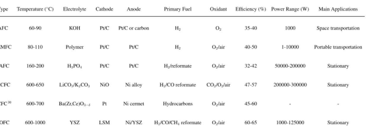
FC are generally classified according to the electrolyte. It can be solid (ceramic or
poly-mer), liquid (aqueous or molten) and must have high ionic conductivity (O2 ,OH ,H+,or
CO2
3 ,) but neglegible electronic conductivity. Table 1.1 reports the characteristics of the
different fuel cell types according to this classification23,29:
• AFCs (alkaline fuel cells) use an alkaline electrolyte and are fuelled with pure hydro-gen and oxyhydro-gen. The charge carriers are OH ions. They work at about 60-90 C. This technology was largely used for space missions in the 60s;
• PEMFCs (proton exchange membrane fuel cells) operate at temperature slightly higher than AFC (80-110 C), upon hydrogen but also reformed natural gas from which CO has been removed. The electrolyte is a proton conductor constituted by a water-based acidic polymer membrane. The metal needed at the anode to catalyze the oxidation of the fuel can suffer of poisoning from the CO that can be present in reformed hydrogen used as a fuel;
• PAFCs (phosphoric acid fuel cells) use H3PO4immobilised in SiC as electrolyte and
are then based on H+ conduction. They operate at 160-200 C upon reformed
hydro-gen;
• MCFCs (molten carbonate fuel cells) require, as electrolyte, eutectic mixtures of alkali carbonates in the molten state, CO2
3 conductors. They work in the 600-650 C range,
where the CO contained in reformed hydrogen can be used as a fuel upon oxidation to CO2;
• PCFCs (protonic ceramic fuel cells) are a relatively new type of fuel cells based on proton conducting oxide electrolytes. They work at about 600-700 C, using hydrocar-bons as fuel.
Chapter 1 General Context and Objectives Type Temperature ( C) Electrolyte Cathode Anode Primary Fuel Oxidant Efficiency (%) Power Range (W) Main Applications
AFC 60-90 KOH Pt/C Pt/C or carbon H2 O2 35-40 1000 Space transportation
PEMFC 80-110 Polymer Pt/C Pt/C H2 O2/air 40-50 1-10000 Portable transportation
PAFC 160-200 H3PO4 Pt/C Pt/C H2/reformate O2/air 32-42 50000-200000 Stationary
MCFC 600-650 LiCO3/K2CO3 NiO Ni alloy H2/CO reformate CO2/O2/air 47-57 200000-300000 Stationary
PCFC30 600-700 Ba(Zr,Ce)O
3 Pt Ni cermet Hydrocarbons O2/air 45-60 -
-SOFC 600-1000 YSZ LSM Ni/YSZ H2/CO/CH4reformate O2/air 60-65 1000-125000 Stationary
Table 1.1: Types of fuel cells and their characteristics. Adapted from29 and completed.
• SOFCs (solid oxide fuel cells) use solid oxide electrolytes, O2 ion conductors. They
require high temperatures (600-1000 C), but allow the use of hydrocarbon fuels to-gether with H2/CO.
Fuel cells are often classified also upon their working temperature: AFCs, PEMFCs, and PAFCs can be consequently considered low-temperature, while PCFCs, MCFCs and SOFCs are high-temperature fuel cells.
1.2.2 Fuels for Electrochemical Cells
Hydrogen is the most attractive and cleanest fuel for FC as it produces water as the only by-product with zero GHG emissions. Hydrogen is mainly generated from fossil fuel or
hydrocarbons, but these methods produce also large amounts of CO or CO2 that need be cut
down to an acceptable level to reduce poisoning issues, especially for FC working at low temperatures. The main challenge for fuel cells working on hydrogen is however related to the green hydrogen high cost and to the safety issues for H2 storage and transportation.
Liquid fuels like methanol or ethanol can also be applied. Compared to hydrogen, they are cheap, easy to handle and transport and have potentially higher energy density. Their toxicological and ecological hazard should however be taken into account. For example, methanol is highly inflammable and toxic. Their electrochemical oxidation is also hardly complete and harmful by-products can be formed. For example, the electro-oxidation of methanol produces formic acid and formaldehyde, which is highly irritant, corrosive, toxic and carcinogenic.
High temperature fuel cells like SOFCs and MCFCs can also operate with high effi-ciencies on hydrocarbon fuels. Natural gas is an ideal fuel for its abundance, low cost and distribution infrastructure. Methane can be directly or indirectly (after reforming) used in SOFCs and MCFCs. Finally, these devices can work with very high efficiency on renewable fuels derived from biomass (particularly from non food biomass).29
1.2. Fuel Cells Chapter 1
1.2.3 SOFC
The history of SOFC starts in the 30s of the last century, when Baur and Preis started to work with zirconium dioxide (ZrO2) doped with 15% Y2O3, applicating Nernst’s idea that
this oxide could be an oxide ion conductor.31 These devices consist in fact of a dense solid
oxide electrolyte layer conducting oxide ions and two porous electrodes working in the high temperature range, between 700 and 1000 C. Figure 1.4 schematically shows the operating principles of a SOFC: oxygen molecules introduced at the cathode react with the electrons coming from the external circuit (Oxygen reduction reaction (ORR)), forming oxide ions that migrate through the electrolyte driven by the difference in oxygen chemical potential thus reaching the anode. Here, they are consumed to oxidise the fuel (hydrogen, methane or hy-drocarbons) forming H2O (and/or CO2). The two-electrode reactions and the overall process,
in the case of hydrogen as fuel, are described by equations 1.1, 1.2, and 1.3, respectively. 1 2O2+ 2e ! O 2 (1.1) H2+ O2 ! H2O + 2e (1.2) H2+ 1 2O2 ! H2O (1.3) O2 C A T H O D E A N O D E ELECTROLYTE H2 H2O O2- Load ½ O2 + 2e- ! O2- H2 + O2- ! H2O+ 2e- or CH4 + 4O2- ! 2H 2O + CO2 + 8e- e- e-
Figure 1.4: Schematic representation of SOFC operating principle.
The interest in SOFCs can be explained considering the peculiar characteristics of these cells compared to the other types:
Chapter 1 General Context and Objectives • As shown in table 1.1, SOFCs provide the highest efficiency (60-65% on average) for conversion of electricity, but the overall efficiency can be higher because of the possibility to efficiently use the heat produced for CHP applications;
• They are very fuel flexible. Because of the high temperature they can work on gen without the need of a previous reforming step, but also the direct use of hydro-carbons is allowed. Hydrohydro-carbons can originate from biofuels or from conventional sources.
• They consequently constitute an environmental-frendly way of producing electricity,
since GHG and CO2 emissions derived from the efficient use of these fuels are very
low and they do not contain NOx.
• There is a wide variety of architectures and geometries that can be used for SOFC, like the tubular technology developed by Siemens-Westinghouse or the planar geometry used by Hexis (see figure 1.5).
Figure 1.5: Schematic representation of a) tubular and b) planar SOFC geometries.32
In the following, we will briefly revise the main properties and characteristics of the materials commonly used for the electrodes and the electrolyte in SOFC applications. 1.2.3.1 Cathode Materials
The cathode material for SOFC application must have high electronic conductivity (> 100 S/cm), high chemical stability in humid air, chemical and mechanical (matching thermal ex-pansion coefficients) compatibility with the electrolyte and the interconnects, and high cat-alytic activity toward oxygen reduction reaction takeing place at this electrode. Moreover, it is important that the cathode presents a stable porous microstructure, allowing an easy diffu-sion of gaseous oxygen through the cathode itself to the cathode/electrolyte interface.10,29,33
The state-of-the-art material is still the lanthanum strontium manganite (LSM), an oxide
1.2. Fuel Cells Chapter 1 perovskite material with intrinsic p-type conductivity, that can be enhanced by substitution of La3+ ions with divalent cations like Sr2+. Generally, 0.2 < x < 0.4 ensures high
con-ductivity while mantaining mechanical and chemical compatibility with the state-of-the-art material for SOFC electrolytes YSZ.29LSM has indeed excellent thermal compatibility with
YSZ, with a thermal expansion coefficient of 11.3-12.4⇥10 6 K 1 close to the 10.3⇥10 6
K 1of YSZ in the 500-1000 C range.29,33,34However, LSM and YSZ can react at high
tem-perature with the formation of a new La2Zr2O7 phase, which is way less conducting than
zirconia.35,36 The main disadvantage with LSM use as cathode in SOFCs is though the low
oxide ion conductivity (10 6 S/cm at 800 C10), that is considered the principal factor in
the high polarization losses of LSM for the oxygen reduction.29 The use of composite
cath-odes, where YSZ or other oxide electrolytes are added to LSM, has shown reduced electrode polarization resistance.37,38
Because of the low oxide ion conductivity, LSM is not the ideal canditate for low temperature applications. In this case, lanthanum nickelate perovskites La2NiO4+ have been proposed,
but their long-term stability under SOFC operating conditions is generally unproven.29
An-other possibility, already largely exploited, are the mixed ionic-electronic conductors of the LaxSr1 xCoyFe1 yO3 (LSCF) family, that have higher oxide ion conductivity and faster
kinetics for the oxygen reduction reaction.10 Finally, increment of the electrochemical
ac-tivity for oxygen reduction was observed by Shao and Haile, by substituting lanthanium in the A-site of LSCF with barium to obtain Ba0.5Sr0.5Co0.8Fe0.2O3 (BSCF). BSCF has very
low polarization resistance and high power outputs resulting from the high rate of oxygen diffusion through the material.39
1.2.3.2 Anode Materials
The anode material must have high electronic conductivity (> 100 S/cm), high stability in reducing environments and chemical stability toward all the possible fuels for SOFCs (hydrogen, natural gas, CO, methane, etc...), high catalytic activity toward the fuel oxidation reaction, chemical and mechanical (matching thermal expansion coefficients) compatibility with the electrolyte and the interconnects, and, finally, a sufficient porous structure to ensure the diffusion of the gaseous species through it.
The state-of-the-art material is a Ni-YSZ cermet, especially in H2/H2O atmosphere.40Ni
was widely used in the early phases of SOFC development beause of its stability in the reduc-ing conditions and for its high catalytic activity toward the oxidation of the fuel. However, it also possesses a higher thermal expansion coefficient (13.4⇥10 6K 1)10when compared to
YSZ, shows coarsening of microstructure and no ionic conductivity. For these reasons it has been associated to YSZ, allowing to reduce the sintering of Ni metal and adjust the thermal
expansion coefficient up to 11.6⇥10 6 K 1 for a cermet with 30 vol% of Ni.41 Moreover,
mixing Ni with YSZ introduces oxide ion conductivity, provides better adhesion with the electrolyte, and determines the creation of additional reaction sites by extending the three-phase (electrode, electrolyte, gas) boundary where the oxidation reaction takes place.42One
of the main drawbacks of the Ni-YSZ cermet is the possibility of Ni oxidation with NiO formation. The difference in the lattice structure of this phase can determine mechanical sta-bility issues. This process can happen with thermal cycling or because of carbon deposition
Chapter 1 General Context and Objectives or sulfur poisoning when fuels like methane are used.43,44 In fact, Ni can catalyze methane
reforming, so that it can be used to boost the internal reforming process in SOFCs that oper-ate on methane/woper-ater. However, Ni can also catalyze formation of carbon from these fuels. A high carbon ratio is thus necessary to reduce carbon deposition. High steam-to-carbon ratio means that the fuel is diluted, consequently reducing the electrical efficiency of the cell.
One possible alternative to reduce carbon deposition is the use of Co-YSZ cermet. Co has high stability in reducing atmosphere, high tolerance to sulfur, does not boost carbon formation from hydrocarbons, but its use implies higher costs. Like Co, also Cu is not an active catalyst for carbon formation and Cu-YSZ or Cu-CeO2cermets have also been studied.
The use of CeO2 increases the active catalytic sites for the fuel oxidation. Unfortunately,
sintering of copper limits the pratical applications.10,45
Finally, oxide-based materials with perovskites structure, like La0.75Sr0.25Cr0.5Mn0.5O3
(LSCM), have been extensively studied as promising alternative anodes for SOFCs.29,46
1.2.3.3 Electrolyte Materials
The electrolyte material in SOFCs is responsible for the transport of the oxide ions from the cathode to the anode. It should hence have high ionic conductivity (>10 1S/cm at the
work-ing temperature) and an ionic transferance number close to unity. Electronic conductivity should be low to avoid short-circuits. Since it is in contact with both electrodes, it should be chemically stable in both reducing (fuel side) and oxidising (air side) atmospheres, cor-responding to a large range of oxygen partial pressure 10 20 <p(O
2)<0.21 atm. For the
same reason, it should be chemically and thermally compatible with the electrode materials. Finally, it must have a dense gas-tight structure which, allowing to separate the gas at the
anode and cathode sides, ensures the maximum electrochemical performance.10,29
The state-of-the-art electrolyte is YSZ. Yttrium oxide (Y2O3) is used to stabilize the
cu-bic fluorite structure of zirconia (ZrO2), that otherwise would not be stable at temperatures
lower than 2376 C. Doping not only stabilizes zirconia, but improves its thermo-mechanical properties and determines the ionic conductivity because of the presence of oxygen vacancies in the doped material. 8-40 mol% Y2O3is necessary to obtain the fully stabilized cubic
struc-ture (YSZ). The ionic conductivity, together with the number of vacancies, increases with the dopant concentration reaching a maximum at 8-11 mol% Y2O3and then significantly
de-creases for higher dopant amount, probably because, at higher yttria content, vacancies are
trapped in defect complexes. YSZ shows a conductivity of >10 1 S/cm at 1000 C. It
how-ever rapidly decreases upon temperature reduction.47,48Aging can also lead to a decrease in
conductivity. The main drawback of this electrolyte is maybe the possibility of reactivity with the cathode material that can be detrimental for the fuel cell performance. As already stated, LSM and YSZ react at high temperature with the formation of insulating phases like La2Zr2O7. Also YSZ and LSCF react in a similar way, but at a lesser extent.48 Despite the
high temperatures necessary to obtain high conductivity and the reactivity issues at the cath-ode, YSZ is still difficult to substitute because of the chemical and mechanical stability at high temperature and in a large range of oxygen partial pressure.
1.2. Fuel Cells Chapter 1 1.2.3.4 Applications
SOFCs’ high efficiency allow power systems based on this technology to be applied in many topics with different power range.
Small power SOFC systems (1-5kW) are widely used in residential applications to supply CHP and for remote distribute generation, as well as military applications. The electrical efficiency of the commercialized devices can go from 30 % and 60% with a total efficiency of over 90% in the case of the CHP units. Futhermore, SOFC devices in these power range are also extensively used in Auxiliary Power Units (APU) in trucks.10,13
Adobe Systems, Bank of America, Cox Enterprise, Coca Cola Company, eBay, FedEx, Google, Safeway, Staples, and Walmar are just some of the commercial customers of one of the most successful companies (Bloom energy) that uses SOFC technology in the field of large-scale power generation (>100kW).10,13
Finally, SOFC systems are more difficult to integrate in portable devices (from mW to few hundred of W), because of the longer start-up time and heavier weight compared to the PEMFC systems generally preferred for these applications. However, SOFC compared to PEMFC are way more fuel flexible and do not necessarily require hydrogen, consequently being very attractive also for portable devices. Some microtubular SOFC-based portable power units for leisure (off-grid power for camping, climbing, etc...), emergency, and mili-tary use or for use with electronic devices, like mobiles and laptops, have thus been recently successfully introduced by some american companies, such as Ultra Electronics AMI or Lil-liputian Systems.10
1.2.4 The problem of lowering SOFC operating temperature
The lowering of the operation temperature is one of the main interest of the current research in the field of SOFCs. The target is obtaining reasonable power output and durability in the range of intermediate (IT, 600-800 C), and, more interestingly, of low (LT, 400-600 C) temperatures. By lowering the temperature, tremendous benefits can be obtained, such as use of cheap steel materials for the interconnects, easier and more reliable sealing, rapid start-up, improved durability, higher robustness, decrease in thermal stresses due to thermal mismatch of the different materials, and negligible electrode sintering. All these advantages contribute to SOFCs’ cost lowering and easier maintenance, that are foundamental for their widespread commercialization, especially in the domain of portable applications. In the last years, some reviews have been devoted to IT- and LT-SOFCs materials, applications and perspectives.13,15,49–51
Unfortunately, lowering the operating temperature does not only imply positive effects, but it is also lined to the increase of the electrolyte resistivity and of the electrode polariza-tion, determining a reduction of cell performances.
Concerning the electrodes, the problem is that the processes that take place at the anode and the cathode are thermally activated. Some materials for cathode in LT-SOFCs have been previously described in section 1.2.3.1. Tsipis et al.52,53 have reviewed in detail the
development and performances of SOFC anode materials.
In order to counteract, instead, the increase in the ohmic loss of the electrolyte, two strate-gies are mainly adopted. The first one is the use of thin films of the usual electrolytes, like
Chapter 1 General Context and Objectives YSZ. The electrolyte resistance is indeed proportional to its thickness.54,55 There are,
how-ever, certain theoretical and practical limitations when reducing the electrolyte thickness.56
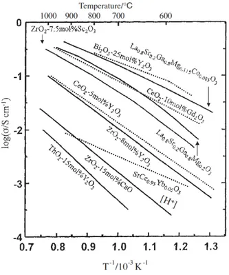
The second way requires the development of new electrolytes with higher ionic conductivity at lower temperatures. The strategies to enhance the ionic conductivities in oxide electrolytes
have been reviewed by Hui et al.57 For example, conductivity can be maximized through
composition modification by selecting an appropriate dopant and its optimal concentration. The doping can be either homogeneous to form a solid solution or heterogeneous to form composites. A brief overview of some of the most studied electrolytes for these applications is presented in the following. Figure 1.6, instead, reports a comparison of the oxide ion conductivity of some of these materials.
Figure 1.6: Oxide ion conductivity of selected electrolyte materials for SOFC application from58
Sc-stabilized zirconia (ScSZ) is an example of the first type of doping. It provides higher conductivities compared to YSZ, attributed to the smaller mismatch in size between Zr and Sc cations. In particular, its conductivity is enough to allow cell operation below 600 C.
However, the costs and known aging of ScYZ present challenges for commercial SOFCs.59,60
Pure ceria (CeO2) is not a good oxide ion conductor, but, as zirconia, it can be doped with
aliovalent cations in order to increase the ionic conductivity. The highest conductivities are obtained for Gd- and Sm-doped ceria (GDC and SDC, respectively) with a doping concen-tration of 10-20 mol% Gd2O3/ Sm2O3. GDC ans SDC have higher conductivity, especially
at lower temperatures, compared to YSZ. This makes them good candidates for SOFC op-erating at about 500-600 C as discussed by Steele.56,61,62These materials also have superior
compatibility with the cathode materials, like LSM and LSCF, compared to YSZ. They are, in fact, used as interlayers between YSZ and the cathode to prevent the reaction.10The main
1.2. Fuel Cells Chapter 1 disadvantage for ceria is its instability in reducing conditions, where it can suffer of partial reduction of Ce4+to Ce3+, introducing electronic conductivity. This can cause internal short
circuit current and generate expansion of the lattice that can lead to mechanical failure.48,49
Lanthanum strontium magnesium gallate (LSGM) materials are doped LaGaO3
per-ovskites with good oxide ion conductivities even at lower temperatures (550-800 C). They have good compatibility with a variety of cathode materials and do not have reducible ions like ceria, being thus superior to GDC for use in reducing atmospheres. The main challenge with these electrolytes is the costs of Ga and the mechanical and chemical stability together with problem of volatilization.10,48
Doped BaCO3 have also drawn special attention as electrolytes for LT-SOFC because of
their high proton conductivity in the 300-1000 C temperature range, even if their chemical instability in atmosphere containing CO2and H2O has limited their practical applications.49
Solid electrolytes with apatite structure, like Ln20 xSi6O26 or La9.33+x/3Si6 xAlxO26
have also been studied since they are low-cost oxides possessing a significant level of oxide ion conductivity. Due to relatively poor sintering, different processing techniques and sub-stantial anisotropy of ionic transport in the apatite lattice, the conductivity values reported in the literature vary broadly even for similar compositions, for example, from 8.4⇥10 5 to
4.3⇥10 3S/cm at 773 K for La
10Si6O27ceramics.47
Cubic -Bi2O3 has a conductivity that is 10-1000 times higher than that of YSZ, but it
also shows various problems, like thermodynamical instability in reducing atmosphere and volatilization of the oxide at intermediate temperatures, that do not allow its direct uses in SOFCs.63 Doping with V, Y, La, Er, Sr, W, for instance, has provided stabilization of the
oxide. In particular, Bi2V0.9Cu0.1O5.35, belonging to the so called BiMeVOx family of ionic
conductors, has an ionic conductivity of 0.1 S/cm at 600 C.50,64
However, none of these materials, all based on homogeneous doping, reach the critical value of 0.1 S/cm in the target range of LT-SOFCs. In their work on enhancing the ionic conductivities in oxide electrolytes, Hui et al.57concluded that there was still absence of well
qualified (phase stability and high ionic conductivity) single-phase electrolyte material at low temperature. Therefore, in the same work, they suggested heterogeneous doping with the formation of two-phases composite materials to improve ionic conductivity of single-phase materials. In particular, in the last decade, carbonate-oxide composite materials have showed promising conductivity values at low temperatures (close to 0.1 S/cm in the LT range).18–22
Since this work is entirely devoted to the study of the conduction properties and mechanisms of these materials, a more detailed bibliographic report of these composites will be presented in section 1.3.
1.2.5 MCFCs and SOFCs
Because the carbonate-oxide composite materials, to which this work is devoted, combine the characteristics of MCFC and SOFC electrolytes, before closing the section on fuel cells, we present a brief overview of MCFC technologies and a simple comparison between MCFCs and SOFCs.
A MCFC is characterized by the use of molten eutectic mixtures of alkali carbonates as the electrolyte. To keep the carbonates in the liquid state, the cell must operate at high
Chapter 1 General Context and Objectives O2 +CO2 C A T H O D E A N O D E ELECTROLYTE H2 H2O+ CO2 CO32- Load ½ O2 +CO2+ 2e- ! CO32- H2 + CO32- ! H2O+ 2e- + CO2 e- e-
Figure 1.7: Schematic representation of MCFC operating principle.
temperatures of about 650 C. Figure 1.7 schematically shows the operating principles of a MCFC: O2/CO2 is fed at the cathode, where reduction takes place leading to carbonate ions
(CO2
3 ) formation. These ions migrate through the molten carbonate electrolyte, reaching
the anode which is fed with the fuel. Here, the fuel is oxidized with formation of water and
carbon dioxide. CO2 formed at the anode can be recycled and consumed at the cathode. The
two-electrode reactions and the overall process are described by equations 1.4-1.7.
CO23 ! CO2 + O2 (1.4) 1 2O2+ CO2+ 2e ! CO 2 3 (1.5) H2+ CO32 ! H2O + CO2+ 2e (1.6) H2+ 1 2O2+ CO2 ! H2O + CO2 (1.7)
As already mentioned, the electrolyte is an eutectic mixture of lithium and potassium (Li0.62K0.38CO3) or lithium and sodium (Li0.52K0.48CO3) carbonates. Li-Na mixtures offer
higher ionic conductivity and possibly higher cell performances. Moreover, they also posses lower oxoacidity and lower effective volatility compared to Li-K ones.65The carbonate
mix-ture is supported by a porous ceramic matrix. The porosity of the matrix should be enough for its impregnation by the electrolyte, but its should also guarantee the separation of the
1.2. Fuel Cells Chapter 1 fuel and oxidant in the two electrode compartments. The matrix should also be stable in the reducing and oxidasing atmosphere and it should be resistent to the carbonate corrosion. The most used matrix material is a lithium aluminate (LiAlO2) powder.66
The most used material for the cathode of MCFCs is NiO. NiO is a p-type semicon-ductor, in whose lattice alkali cations provided by the electrolyte can be incorporated. The incorporation of these species, lithium in particular, determines the creation of positive holes in the NiO crystal structure enhancing the conductivity. The main drawback associated to the material is NiO dissolution in the electrolyte, leading to the loss of cathode surface area for the oxygen reaction reduction and to possible short circuit. In order to reduce this issue, adjustments of the carbonate acidity (by addition of alkaline earth metal oxides or Ba or Sr carbonates to the elecrolyte) and the use of other cathode materials like LiCoO2 have been
proposed. LiCoO2 has higher stability and lower solubility in the carbonate electrolyte, but
also higher costs and lower electrical conductivity.29,65
Finally, Ni-Cr or Ni-Al alloys are used at the anode. Cr or Al are added to reduce the problem of shrinking and creeping of porous Ni during MCFC operation. However, Cr has the tendency to consume through lithiation by the carbonate, while Ni-Al showed excellent chemical and mechanical stability in a 18000 h field operation.29,66
What differenciates SOFCs and MCFCs from the other fuel cell types is their high operat-ing temperature. As previously mentioned, MCFCs’ standard operation temperature is about 650 C, while SOFCs work in a larger temperature range between 600-1000 C, depending on the selected electrolyte. Moreover, contrarily to the other fuel cells, SOFCs included, MCFCs require supply of CO2at the cathode and are generally equipped with a CO2transfer
device to recycle the anodic gas to the cathode.
Compared to the other FC types, SOFCs in particular, MCFCs have the steepest polariza-tion curve resulting in the lowest current densities at high power range and high efficiency in
the limited range of low current (up to ⇠ 150 mA/cm2). Moreover, among hydrogen-oxide
fuel cells, they show one of the thickest electrodes-electrolyte assembly (1-3 mm) and the thickest electrolyte to reduce NiO dissolution (0.5-1.5 mm).67Performance improvement in
MCFCs can be obtained by reducing cathode polarization. In PAFC, PEMFC, and SOFC, the effectiveness of the cathode operation is improved by special techniques of electrode fabrication that are useless in the corrosive environment of the carbonate electrolyte.67
MCFC lifespan-limiting phenomena are caused by the corrosive and evaporative electrolyte, the relatively high operating temperatures, and stack pressure. These phenomena include dis-solution of the NiO cathode, high-temperature creep and sintering of the porous components, reforming catalyst deactivation, electrolyte losses and electrolyte retention capacity, corro-sion of the separator plate, and matrix cracking.68Another difficulty of molten carbonates is
the lithium alluminate matrix used, which is responsible of about 70% of the ohmic drop in the cell. The nature of the electrolyte consequently creates the main differences with respect to SOFCs. In SOFC technology, the fact that all components, including the electrolyte, are in the solid state can help in prolonging the lifetime and in making industrialization easier compared to MCFC with liquid electrolytes.
However, MCFCs have also some clear advantages compared to SOFCs: (i) their oper-ating temperature is optimal for internal reforming and exploiting of usable heat, while in
Chapter 1 General Context and Objectives SOFC it is generally too high to use cheap, steel elements; (ii) MCFC technology is more established than SOFC, especially for SOFC working in the intermediate or lower tempera-ture range, and (iii) because of the liquid electrolyte, low contact resistance and gas seal are
more easily achieved in MCFC than SOFC.67
Concerning MCFCs and SOFCs commonalities, it should be mentioned that the high temperatures, common to both fuel cell types, allow to efficiently use the heat produced in the conversion process in heat generations systems, thus improving the overall efficiency of the devices. More importantly, high temperatures make these fuel cells independent of a pure hydrogen infrastructure, since they enable the possibility of hydrocarbon reforming taking place directly inside the cell, since the heat released by the electrochemical oxidation of the fuel can be used for the reforming reaction. Similarities between MCFCs and SOFCs consequently exist, especially on the anode side, where the fuel oxidation takes place with Ni-based catalysts in both cases. Therefore, MCFCs and SOFCs share the same challenges related to the internal reforming process of hydrocarbon fuels at the anodic compartments. Poisoning of the anode because of sulfur contaminants present in the fuel (summed to chem-ical reactivity of these impurities with the carbonate electrolyte in the case of MCFCs) and carbon deposition issues are common in both applications. Facing these problems can con-sequently constitute an opportunity for integrated research.66
Finally, among the similarities, it must be also considered the fact that both technologies can be applied for carbon dioxide separation from conventional power plant exhaust gasses, which is beneficial in the perspective of exploiting coal as fossil fuel.67
1.3 Composite Materials
Composite materials are heterogenous mixtures of two or more phases. Heterogeneous dop-ing requires mixdop-ing of phases with limited solubility and determines the creation of inter-faces with peculiar properties that are believed to be essential to explain the characteristic features of the final materials. The effect of the heterogenous doping strongly depends on the chemical nature of the components, but also on the morphology of the system. The pos-sibility to optimize the composite properties by varying the type and concentration of the heterogeneous dopant makes this kind of materials extremely interesting for electrochemical applications.69–71Composite electrolytes, in particular, are systems consisting of two or more
phases mixing different ionic conductivity properties. They generally show enhanced elec-trochemical features (high conductivity, high transference number, high diffusivity, etc...), that could also be accompanied by improved mechanical properties, such as better shock resistance or higher mechanical strength.69–71
Conductivity enhancement in composites was known since the beginning of the early 20th
century, when reported by Jander in 1929.72 However, the interest in this kind of materials
started to grow only after the study of Liang in 1973,73 reporting an increase of the ionic
conductivity by a factor 50 with the incorporation of alumina in LiI. Since Liang’s work, a
large number of composite ionic conductors have been investigated. Agrawal and Gupta70
have provided an extensive list of the composite electrolyte systems reported in literature. Composites are generally prepared by milling dry powders pelletised by appliyng a
pres-1.3. Composite Materials Chapter 1 sure of several kbar. In many works, the pellets are heated, cooled and regrounded before the final pelletizing to ensure a better mixing of the components. X-ray diffraction is the most used structural characterization technique, while scanning electron microscopy is used to ob-serve morphology. Electrochemical impedance spectroscopy (EIS) is by far the most impor-tant electrochemical characterization technique, since it allows to separate the contributions of bulk and blocking components (grain boundaries, insulating phases, etc...). Sometimes, ion mobilities are studied through NMR spectroscopy, such as for Li ion conductors consid-ering the high resolution of7Li-NMR. Differential thermal analysis and calorimetry are also
frequently applied to check for the eventual formation of new phases as well as modifications of phase transition temperatures.71
1.3.1 Space Charge Layer Theory
The theory of ionic conductor composites explaining the reasons for the conductivity en-hancement is rooted in the early works of Gouy,74who established the theory of the electrical
double layer at the electrode-electrolyte interface in 1903, and of Lehovec, who calculated in 1953 the defect distribution at the surface of ionic crystals and introduced the ”space-charge layer” theory, based on the idea that the difference between the concentration of lattice de-fects near the surface and that in the bulk of ionic crystals led to an electrostatic potential between the bulk and the ”surface zone” which influences the transport of the ions at the surface.73In 1963, Kliewer and Koehler75further developed the space charge model in ionic
crystals. On these bases, in 1972, Wagner explained the electrical conductivity of
semi-conductors including another phase using this ”space-charge layer” concept.76 Few years
later, in 1979, Jow and Wagner77, in their study on the effect of dispersed alumina particles
on the electrical conductivity of cuprous chloride, attempted for the first time to formally introduce the ”space-charge model” of composite materials. Finally, between the ’80s and the early ’90s, Maier established the ”space-charge layer” theory of heterogeneous ionic conductors, giving a quantitative treatment of two-phases systems, made by an ionic con-ductor and insulator or by two ionic concon-ductors.78–84The theoretical concepts on conduction
in ionic conductor composites were reviewed by Knauth71 in 2000 and more recently by
Belousov.85In the following, we will briefly revise the most important concepts.
The first thing to bear in mind is that the effects responsible for the conductivity en-hancement in composites are not simply additive, but rather synergistic, since the whole system is more than the sum of its parts. Interfaces between the two materials are believed to play a major role in the processes determining the improvement of the conductivity, the so called composite effect. First, interfaces themselves are disordered regions and, given their anisotropy, they can act as transport pathways or transport barriers and can affect the charge carrier distribution in the adjacent regions (space charge effect).71 In fact, different
conductivity effects may occur at the interfaces as a consequence of the interaction between the two materials: i) a proper interface mechanism characterized by a novel conductance path; ii) a space charge mechanism which should be mainly characterized by modified de-fect concentrations as a consequence of the interface interaction.81For example, impurities
may diffuse from the interface and create mobile defects or act themselves as charge carrier (e.g. protons), dislocations can be formed to compensate lattice misfits, amorphous phases
Chapter 1 General Context and Objectives can be formed at the interfaces or lattice deformations near the interface can enlarge the free volume. All these phenomena generally provide a new conduction mechanism in the zone adjacent to the phase boundary and, therefore, have an activation enthalpy different from the bulk value69,71,81 and they reveal a very individual transport problem.81 The space charge
mechanism, instead, is of very general nature and is directly related to the thermodynamic describing the equilibrium of the interface interaction.
The space charge model takes an idealized view of interfaces and a major assumption is that the bulk structure is maintained up to the atomic layer in contact with the interface, but it is based on the idea that the mixture of two phases involves formation of defect concentration profiles in the proximity of the interfaces, the deviation from local electrical neutrality (space charges) are hence a consequence of point defect equilibrium at interfaces. The general principle at the base of the space charge theory is the possibility of influencing the defect chemistry in the boundary layers through surface reactions between the two phases. As a result of these reactions, ions can be indeed trapped at the interfaces. The driving force for trapping is the chemical affinity of the second phase for the mobile ions. According to the principle of global electrical neutrality, in order to compensate the accumulation of electronic or ionic charge at the phase boundaries, the formation of space charge regions near the interfaces, where the counter species of the defects are consequently accumulated, should be induced. For example, for a Frenkel-disordered ionic crystal M+X , this process
can be written as
MM + VS ! MS• + V
0
M (1.8)
whereVS and M•Sare respectively an empty interface site and metal ion trapped at the
inter-face site. Metal ions are sucked out of the volume of the MX phase and trapped at the in-terface, while vacancy concentration in the adjacent space charge layer will increase. Space charge effects are pronounced at reduced temperature, due to the low bulk defect concentra-tions. If the majority charge carriers are accumulated in the space charge regions, a consid-erable conductivity enhancement may result.
Apart from the space charge layer theory, other models were proposed to explain the enhancement of the ionic conductivity of composites. The percolative model, for example, can be considered complementary to the space charge one. The percolation concept is based on a random distribution between two phases assuming also no interaction between phases and constant grain size.71,85 Jiang and Wagner86 suggested a model in which the composite
effect was explained in terms of the formation of an amorphous phase at the interface, while Belousov proposed a model in which the conductivity increase is related to the formation of a highly conducting interfacial liquid phase.85,87
1.3.2 Carbonate/oxide electrolytes
In 1994, Zhu and Mellander88 reported for the first time the high ionic conductivity in the
composite materials containing one molten phase. After this publication, a series of
1.3. Composite Materials Chapter 1 with chlorides, fluorides, sulphates, hydroxides and carbonates have been widely
investi-gated.89–91 Among them, ceria-carbonates were found to be the most promising ones with
high ionic conductivity and excellent fuel cell performances.18 Conductivities of the
or-der 0.1-1.0 Scm 1 were achieved at 400-600 C together with electrochemical power output
higher than 800 mWcm 2at 600 C for hydrogen fuel cells.92These conductivity values are
10000 higher than those of YSZ and 10-100 higher than that of GDC in the same temperature range (see figure 1.8). After the first work introducing these materials by Zhu18, more than
100 papers have been published on this subject. The most important features and the perfor-mances of these materials have been reviewed in some papers, where detailed information can be found.51,89,92–96
Figure 1.8: Temperature dependence of the conductivity of various ceria-salt composites
compared to the conventional SOFC electrolytes, like YSZ and GDC.18
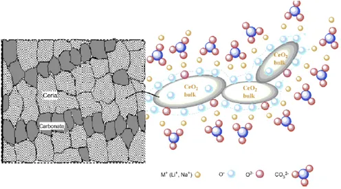
These carbonate-oxide composites are multi-phase materials, where the carbonate salt is supported on the solid oxide phase. The two phases are not a simple mixture, since there are some physical interactions between them, but no other compound is to be formed. The conductivity is not limited by the structure, but it is believed to be greatly influenced by com-posite effects: the oxide provides the conducting path for the oxide ions, while the presence of the carbonate can cause extremely high conductivity due to interfacial effects, without weakening the mechanical strength. On the contrary, the chemical stability and strong me-chanical strength of the oxide can benefit the whole system and provide advantages in less corrosion compared to the pure molten carbonate phase. Moreover, a suppression of the electronic conductivity that arises in doped-ceria oxides in anode environment is observed in the composites because of the presence of the carbonate phase. Finally, as we will see in the following, these composites are believed to integrate multi-ion conduction in one system, forming hybrid conductors.89,97
The composition of these materials is a mixture of those used in SOFCs and MCFCs, combining the advantages of the two technologies in a new hybrid material. Concerning the