Science Arts & Métiers (SAM)
is an open access repository that collects the work of Arts et Métiers Institute of Technology researchers and makes it freely available over the web where possible.
This is an author-deposited version published in: https://sam.ensam.eu
Handle ID: .http://hdl.handle.net/10985/6314
To cite this version :
Fouad SALHA, Frédéric COLAS, Xavier GUILLAUD - Grid Connected Inverter Behavior with an Output LC Filter under Voltage Sag Operation - 2009
Any correspondence concerning this service should be sent to the repository Administrator : archiveouverte@ensam.eu
Grid Connected Inverter Behavior with an Output LC Filter under Voltage Sag
Operation
Fouad SALHA (*), Frédéric COLAS (*), Xavier Guillaud (**)
(*) L2EP, ENSAM CER de Lille
8, bd Louis XIV 59046 LILLE CEDEX France
(**) L2EP, Ecole Centrale de Lille, Cité Scientifique, BP 48
59651 VILLENEUVE D’ASCQ CEDEX France
Tel: +33/ (3) 20.62.29. 43
Fax: +33/ (3) 20.62.27.50
fouad.salha@ec-lille.fr , frederic.colas@lille.ensam.fr , xavier.guillaud@ec-lille.fr
Keywords
«Distributed generation», «Voltage Source Inverter (VSI) », «Current limiter», «LC output filter», «fault detection», « Voltage sag», «Resonant controller», «Pole assignment».
Abstract
The aim of this paper is to propose an over current limitation and voltage control strategy for a grid connected inverter with a LC output filter used in distributed generation and in case of voltage sag. This strategy relies on the control of LC output filter voltage with a resonant controller. This controller has to control current and load voltage throughout voltage sag. Generally, resonant controller is made up of a proportional and resonance term, which contains two imaginary poles that aimed to obtain an infinite gain at the resonance frequency. State feedback structure and pole assignment approach are used to tune the proposed control strategy. Comparative results for the application of both resonant and classical PI controller in d-q frame are showed in this paper. The last part deals with the implementation of control strategies on a real time simulation environment. The effectiveness of the proposed controller under a voltage sag operation is shown by experimental results.
Introduction
The electricity market’s liberalization and the significant and rapid growing of distributed generation sector due to the trend for a large integration of renewable energy in electrical power systems provide impetus to highly reliable good-quality electrical power generation. Generally, three-phase voltage inverters have been widely used in this new sector of power system. Therefore, the need of these inverters has introduced the necessity of achieving a high power quality with low output distortion [1]. Filters are, thus, used for grid interfacing of these inverters in order of decrease the harmonics injection into the grid. In power system with distributed energy, the low voltage distributed energy sources such as, gas micro turbine, photovoltaic system, wind turbines,etcstorage devices such as, flywheel, super capacitor, batteries and controllable load form an energy system structure classically named microgrid [REF?]. Microgrid can operate either in parallel with the utility grid or in stand-alone mode to form an islanding system. In the first case, in the grid-connected mode, L and LCL filters are usually used to connect inverters and main grid [REF?]. According to the previous operation mode, the generator work as a current injector to the main grid [2,3] while the main grid fixes the voltage to generators of microgrid. On the other hand, in stand alone mode, the loads in a microgrid can receive power from the local microsources, depending on the customer’s situation [4]. In addition, a microgrid must have at least one voltage generator which control microgrid voltage in an islanding operation mode. Thus, three-phase voltage inverters must be equipped by an output LC filters which are usually used to fix output voltage and attenuate voltage harmonics.
One of the most important problems which happens continuously in transmission and distribution systems and affects the power quality is voltage sags. Many reasons are the origin of this problem, such as short circuit, transformer energizing, capacitor bank charging etc. During a voltage sag event, the amplitude of effective load voltage can decrease from 100% to 10% of its nominal load voltage to 0.1 in a very short time (less than one minute).
This paper deals with this operation mode mentioned above, and suggests a robust LC filter control method. Voltage sag problems will be treated in detail in the proposed control system using two different controllers; resonant and PI controllers in d-q frame. Contrary to vector control with synchronous PI controllers, resonant controller can be used to control non-linear disturbances. In addition, the synchronous d-q coordinate transformation cannot work in single-phase systems [6]. So a stationary reference frame control method, that introduces a cosine transfer function with a specified resonant frequency into the voltage compensator, is proposed in this paper. This controller is generally made up of a proportional and a resonance term, which contains two imaginary poles that aimed to obtain an infinite gain at the resonance frequency.
This paper is divided into three main sections. First, resonant controller with state feedback structure is designed using poles assignment method. Then, analysis of system behavior in case of voltage sag caused by a short circuit will be discussed; two different control strategies will be presented. One depending on the common method realized in d-q frame, and the other, is the proposed method depending on resonant controller. Finally, comparative results obtained and comparative study will be discussed.
Control of a three phase inverter with LC filter: resonant controller structure
The overall proposed control system of the inverter with an output LC filter is summarized in Fig. 1. This control strategy aims to generate a voltage, at the output of LC filter, identical to the reference voltage signal. In fact, voltage control is established by mean of a resonant algorithm in order to control the instantaneous value of voltage. A Synchronization of the grid-side converter voltage with the grid voltage is established and carried out by a phase lock loop (PLL).
Fig. 1: Scheme of LC filter voltage control
The control method is based on state feedback for state variables which are LC filter, current and output voltage, and the two state variables of the controller itself. State models for both LC filter and resonant controller must firstly be formulated.
LC Filter modeling
A state model of a single phase LC filter is carried out by using the voltage and current equations depending on the state variables that are the inductance current is and capacitor voltage uc (see Fig. 2).
s sR L , s i c i m u uc r i C s sR L , s i c i m u uc r i C s i c i m u uc r i C
Fig. 2: Single-phase LC filter dt s di s L s R s i c u m u . . (1) dt c du C r i s i (2)
The control variable is the input filter voltage um as denoted by (3):
r i C m u s L c u s i C s L s L s R c u s i dt d . 1 0 . 0 1 . 0 1 1 (3)
c u s i p X s L p B C s L s L s R p A , 0 1 , 0 1 1 (4)
A three phased model is derived from this single phased model using coupling and decoupling matrix as explained in part C.
Resonant controller modeling
Many structures of resonant controller have been already used for current control as in [1, 3, 7, 10], this controller has a proportional and cosine transformed resonant element. The transfer function is described by:
2 0 2 ) ( s s i k p k s G (5) In order to use this control algorithm in a state feedback control, state representation of this controller is proposed: e u y p u y dt d 0 1 0 1 2 0 (6)
Where state and command matrix and the state variable vector are respectively:
u y c X c B p c A , 0 1 , 0 1 2 0 (7)
Where y and u are the state variables, and e is the control variable.
State feedback control, poles placement approach
When the state variables of a system are known (either through measurement or estimation), it is possible to feed their values back to the inputs with a controller in order to determine the system dynamic, this is the principle of the state feedback structure [7]. State feedback voltage control is realized for single-phase equivalent system as depicted in Fig. 3.
e B X A dt dX c c c c . . p p p p p u B X A dt dX . . Yp Cp.Xp c K c K + - -e Xc up Xp Yp ref p Y_ e B X A dt dX c c c c . . p p p p p u B X A dt dX . . Yp Cp.Xp c K c K + - -e Xc up Xp Yp ref p Y_
Fig. 3: State feedback voltage control scheme
Firstly, we design the control for a single phase LC filter by calculating the matrix vector of gains (K) for state variables of both controller and filter Xc and Xp respectively. Then the mathematical matrix which describes the previous system denoted by state form is:
pref y c B c X p X c A p C c B c K p B p K p B p A c X p X dt d 0 0 (8)
Where p index refers to the process (LC filter) and c to the controller. As the transfer function of LC filter is of second order, that means we have two poles, and resonant controller has the same number of poles. Then state feedback gain matrix is determined in such a way that 4 conjugated closed-loop poles have the same real part. This is realized via the pole assignment technique, as in [7], which aims at designing the feedback controller by placing the poles of the closed-loop system at desired locations as shown in Fig. 4.
Then, the coefficients of controller can be identified from the characteristic polynomial of the closed-loop transfer function of the system by a polynomial criterion as in this equation:
N n i R i b a n i i jb a s i jb a s s P ; , ; , 1 ) ( (9)
Where a sets the dynamic response and the control system stability. Pole placements were chosen in such a way that the closed dynamic has two double poles. For this purpose, the angle θ, mentioned in the above Fig. 4, corresponds to damping ratio of 0.7.
Application to a three phase system
The designed controller for the single phase system is also applied to the three phase system. This will be achieved by modifying of the system representation using coupling and decoupling matrix shifting. Fig. 5 shows three-phase the LC filter used a delta configuration for capacitors connection, denoting to state variables on it.
Fig. 5: Three-phase LC filter
As indicated in single phase model the current and voltage equations are written by the two next equations:
2 2 1 1 3 2 3 1 3 1 3 2 1 2 1 2 1 C u m u C u m u s L s i s i s L s R s i s i dt d (10) 2 2 1 1 3 / 2 3 / 1 3 / 1 3 / 2 2 1 r i s i r i s i C C C C c u c u dt d (11)
Depending on these above equations, we define:
2 1 3 / 2 3 / 1 3 / 1 3 / 2 2 1 m u m u m v m v 2 1 3 / 2 3 / 1 3 / 1 3 / 2 1 1 c u c u c v c v C C' 3 It comes: 2 2 1 1 2 1 2 1 c v m v c v m v s i s i s R s i dt d s L s R s i dt d s L 2 2 2 ' 1 1 1 ' r i s i dt c dv C r i s i dt c dv C
In a similar manner as in single phase LC filter modeling, state equations for the two new phases are formulated in these two state equations:
1 . ' 1 0 1 . 0 1 1 1 . 0 ' 1 1 1 1 r i C m v s L c v s i C s L s L s R c v s i dt d (12)
This leads to two decoupled set of equations for phase1 and the same for the phase 2. Then it is possible to apply the same feedback control on both decoupled systems.
Behavior in case of voltage sag
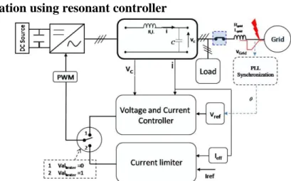
In a classical L or LCL grid connected converter, the control aimed at regulating the grid current. In case of voltage sags, the current is naturally limited. In a LC grid converter, which is usually used in isolated mode operation, the output voltage is controlled. In case of voltage sag, the converter current tends to increase to support the output voltage level as in [8]. In this paper, a specific control strategy has been deduced to maintain the current in an acceptable level. By means of this current limitation, the distributed generator with used power electronic equipments will be protected automatically protected from the overcurrents. For achieving this purpose, two strategies were adapted. The two strategies depend on modifying the overall control system, from a voltage control to current control during voltage sag occurrence (see. Fig. 6). But the
first one uses the classical PI controller for the two control stages. The second method which is the new proposed method uses the resonant controller for the two control stages.
Overcurrents limitation using resonant controller
Fig. 6: Block scheme for control strategy in case of voltage sag
The current limiter, which is also resonant controller, limits the inductor LC filter current during the voltage sag to a reference imposed value. In order to design the current limiter, controller parameters have to be calculated depending on poles placement method. For this objective, we have used the same state model for the resonant controller as in (6), (7).
As we want to control the inductor current, so a state model has to be realized for L filter as explained in (13): m u s L s i s L s R s i dt d . 1 . (13) s i p X s L p B s L s R p A . 1 ,
Where Ap, Bp, Xp are the state, command and state variables matrix respectively. The poles placement regulation was set to the same regulation as in the voltage controller.
Switching operation takes into account that at start-up operation and without the existing of voltage sag, the inverter works as a voltage generator (vallimiter=0 and switch on position 1 “see Fig. 6”). The next stage is
during the voltage sag, where the switch disconnects the above controller and then connects the current limiter (vallimiter=1 and switch on position 2 “see Fig. 6”) when the current exceeds a maximum current value.
After the voltage sag clearing, switching operation will return to voltage and current control mode. Voltage sag detection and switching between the two controls strategies was realized by state flow and illustrated in Fig 7.
Overcurrents limitation in dq coordinates
The control system consists of two multi-loops, the outer is the voltage control loop which regulates the output capacitor voltage and sets the reference for the inner current control loop (see Fig. 8). Considering that the inverter works in a grid-connected mode, so a phase lock loop (PLL) is used to synchronize this inverter with the grid.
Fig. 8: Multiple-loop control of an inverter
The current loop was designed to have a high bandwidth 4.4 kHz while the voltage loop is much slower with a smaller bandwidth of 600 Hz. We use PI controller for dq coordinates which are of a dc terms under a balanced operation. As we don’t have a ground connection for the inverter (three wires), so the zero sequence is not present when the fault appears. During the voltage sag, the inverter fault current is limited to a desired constant value. This limitation was carried out in such manner that as soon as the current reaches its limits, the control loop shown in Fig. 8 will be converted to a constant current source by means of a flowchart stat depicted on Fig. 7.
Realization and Discussion
The two control strategies explained previously were constructed on Matlab SimulinkTM, then, it was implemented on SPS environment with the parameters presented in TABLE 1. Two tests were realized for each control strategy, the first is that during the voltage sag caused by three phase balanced fault, the other is that caused by a three phase unbalanced voltage sag. For the two tests, the PLL loop was set to a dynamic corresponds to 25 ms. The unbalancing on the network voltage is obtained by reducing the phase 1 voltage to 50% of the nominal value. The reference current desired obtained during the voltage sag was set to 30 A. this value was easily imposed for the first method (resonant controller), for the method in dq coordinates, the saturation limits was set in order to have 30 A as peak value.
Table 1: Simulation system parameters
Network inductance (Lgrid) 0.17 mH
Network resistance (Rgrid) 0.7ohm
LC filter resistance (Rs) 0.1 ohm
LC filter inductance (Ls) 1 mH
LC filter capacity 20 µF
Operation voltage magnitude 240v
DC bus voltage 760 v
DC bus capacity 5 mF
a complex pole real part (for two controllers)
2000 b complex pole imaginary part (for two controllers)
1400
Current Limit value 30 A
Load (P+jQ) 3000(w)+j100(var)
Response time for voltage controllers 10 ms
Response time for current controllers 1 ms
According to the results (see Fig. 9-10), firstly, in case of balanced voltage sag, we can see a very small difference between the two current limitation methods. Where, for balanced voltage sag on the network voltage, as depicted in Fig. 9-10-a, the two methods give a similar output balanced voltage (see Fig. 9-10-b).
Nevertheless, the two methods introduce a transition stage on LC filter current at the moment of voltage sag occurrence and its elimination (see Fig. 9-10-c).
On the other hand, in case of unbalanced voltage sag, the effects on the output voltage are the same as in balanced voltage sag (Fig 9-10-e). Contrariwise, the proposed method presents a better comportment with regard to current during the voltage sag. We can note, in regarding Fig. 9-10-f that the current limiter based on resonant controller solves the problem of unbalancing in the current which comes from the unbalanced output voltage. Fig. 11-12 depict the direct and quadratic components of the LC filter inductor current. The ripple shown on the direct and quadratic components of LC inductor current come from the unbalancing voltage. And in case of resonant controller, the ripple, which is of frequency of (2 ), is much smaller than that resulting from PI controller.
Conclusion
In this paper, a method proposes a solution for the Balanced and unbalanced voltage sag problem. Resonant controller for LC output voltage was introduced. Furthermore, control tuned by the pole assignment technique was used for control design. PI controller in d-q frame was applied on the same system. Comparison results were presented. Taking into account that on the grid side, the current and voltage are controlled by action on the inverter, and in addition that primary generator control keeps the DC-bus voltage constant, therefore the control strategy based on resonant controller, as the other strategy, can be easily implemented on every voltage generator.
References
[1]. N. Hatziargyriou. “MICROGRIDS: Potential Allies for a More Efficient Power Supply”. Key Note Speech,
Medpower’04, Cyprus, 2004.
[2]. F. Blaabjerg, and al “Power converters and control of renewable energy systems. Presented at Plenary Speech
ICPE’04. [CD-ROM].
[3]. M. Liserre, R. Teodorescu, F. Blaabjerg « Stability of Photovoltaic and Wind Turbine Grid- Connected Inverters for
a Large Set of Grid Impedance Values »IEEE transactions on power electronics, vol. 21, No. 1, January 2006.
[4]. Jaehong Kim, Junggi Lee and Kwanghee Nam “Inverter-based local ac bus voltage control utilizing two DOF
control” IEEE transactions on power electronics No. 3, may 2008 control”. IEEE transactions on power electronics
[5]. H. Nasiraghdam, and A. Jalilian “Balanced and Unbalanced Voltage Sag Mitigation Using DSTATCOM with
Linear and Nonlinear Loads”. International Journal of Electrical, Computer, and Systems Engineering 1;2 Spring 2007.
[6]. J. ZENG, Ph. DEGOBERT, D. LORIOL, J.P. HAUTIER “Robust Design of the Self-tuning Resonant Controller for
AC Current Control Systems” 0-7803-9484-4/05/$20.00 ©2005 IEEE.
[7]. López de Heredia, and al “Analysis of Multi-Resonant Current Control Structures and Tuning Methods”
1-4244-0136-4/06/$20.00 '2006 IEEE.
[8]. R. CALDON, F. ROSSETTO, R. TURRI “Analysis of dynamic performance of dispersed generation connected
through inverter to distribution networks. CIRED, 17th International Conference on Electricity Distribution Barcelona, 12-15 May 2003.
[9]. V. COURTECUISSE, M. EL MOKADEM, X. GUILLAUD, F SALHA, B.ROBYNS” Use of real time simulation
to validate primary frequency control with wind turbine “IEEE PES General Meeting, Pittsburg, 20-24 July, 2008.
[10]. M. BRUCOLI, Tim C. GREEN “Fault Behaviour in Islanded Microgrids” CIRED 19th International Conference
(a) Network voltage (b) LC filter terminal voltage (c) LC filter inductor current
(d) Network voltage (unbalanced
voltage sag) (e) LC filter terminal voltage
(f) LC filter inductor current
Fig. 9: Simulation results for proposed method depending on resonant controller
(a) Network voltage (b) LC filter terminal voltage (c) LC filter inductor current
(d) Network voltage (unbalanced
voltage sag) (e) LC filter terminal voltage (f) LC filter inductor current
0.35 0.4 0.45 0.5 0.55 0.6 0.65 0.7 0.75 0.8 0.85 -80 -60 -40 -20 0 20 40 Time (s) D ir e ct co m p o n e n t fi lt e r cu rr e n t isd ( A ) isd PI isd resonant 0.58 0.59 0.6 0.61 0.62 0.63 0.64 0.65 0.66 0.67 0.68 -0.6 -0.4 -0.2 0 0.2 0.4 0.6 Time (s) D ir e ct co m p o n e n t fi lt e r cu rr e n t isd ( A ) isd PI isd resonant
Fig. 11: Direct component of inductor filter current for the two control methods
0.35 0.4 0.45 0.5 0.55 0.6 0.65 0.7 0.75 0.8 0.85 -80 -60 -40 -20 0 20 40 Time (s) Q u a d ra ti c L C f ilt e r c u rr e n t c o m p o n e n t is q ( A ) isq PI isq resonant 0.58 0.59 0.6 0.61 0.62 0.63 0.64 0.65 0.66 0.67 0.68 -37.2 -37 -36.8 -36.6 -36.4 -36.2 Time (s) Q u a d ra ti c L C f ilt e r c u rr e n t c o m p o n e n t is q ( A ) isq PI isq resonant