HAL Id: hal-02127580
https://hal.archives-ouvertes.fr/hal-02127580
Submitted on 13 May 2019
HAL is a multi-disciplinary open access
archive for the deposit and dissemination of
sci-entific research documents, whether they are
pub-lished or not. The documents may come from
teaching and research institutions in France or
abroad, or from public or private research centers.
L’archive ouverte pluridisciplinaire HAL, est
destinée au dépôt et à la diffusion de documents
scientifiques de niveau recherche, publiés ou non,
émanant des établissements d’enseignement et de
recherche français ou étrangers, des laboratoires
publics ou privés.
reaming of aluminium 2024-T351
Alexandra Lacombe, Yann Landon, Manuel Paredes, Clément Chirol, Audrey
Benaben
To cite this version:
Alexandra Lacombe, Yann Landon, Manuel Paredes, Clément Chirol, Audrey Benaben. Numerical
evaluation of residual stress induced by reaming of aluminium 2024-T351. International Joint
Confer-ence on Mechanics, Design Engineering and Advanced Manufacturing, Jun 2018, Cartagena, Spain.
�hal-02127580�
reaming of aluminium 2024-T351
Alexandra Lacombe1, Yann Landon1, Manuel Paredes1, Clément Chirol2, Audrey Benaben2, 1 ICA, Université de Toulouse, UPS, INSA, ISAE-SUPAERO, MINES-ALBI, CNRS, 3 rue Caroline Aigle, 31400 Toulouse, France
2 Airbus France, D41, 18 rue Marius Tercé, 31300 Toulouse
Abstract
In aircraft assemblies, holes for fastening are critical areas from where fatigue damage can be initiated, especially for metal parts. Depending on the operating conditions of the various stages of the machining process of the hole (drilling, reaming, cold expan-sion, second reaming), the manufacturers observe significantly different fatigue strength of the structures. To optimize the behavior of the aircraft assemblies, the manufacturers want to understand the impact of the whole machining process of the hole on the material characteristics of the part. They investigate particularly the resid-ual stress state in the hole edge zone which can be significantly different depending on the operating conditions.
The study, in collaboration with Airbus, focuses specifically on the impact of the reaming on the final residual stress state in parts with initial material state not clean of mechanical stress. Indeed, before the final reaming, the parts undergo at least a drill-ing operation, and sometimes a cold expansion operation. Therefore, they do not pre-sent a zero stress state.
This paper investigates the influence of reaming in an aluminum 2024-T351 part which has been pre-stressed by the cold expansion process. Both processes are simu-lated using a finite element model with Abaqus. The implemented strategy to simulate the reaming process is based on the progressive deactivation of mesh elements. The obtained results show a low relaxation of the circumferential and radial residual stresses in the part during the reaming simulation.
Keywords: Reaming, numerical simulation, residual stress, aluminum
1 Introduction
Fastening holes in mechanical structures are critical areas for the initiation of fatigue damage, especially for metal parts. The experimental study of fatigue strength and failure modes of bolted joints made of aluminum alloy parts is the subject of a lot of
experimental works [1, 2, 3, 4]. Different failure modes are observed. Some failure occurs in the bearing mode, with cracks initiating at the edge of the hole and others occurs in the fretting mode, with cracks initiating away from the hole boundary. Compressive residual stress at the vicinity of a hole resulted in a significant increase in the fatigue lives of holed parts [5]. Indeed, cracks find it much more difficult to propagate through a compressive field. Thus, in the aeronautical industry, processes have largely been developed in order to introduce a compressive residual stress field at the vicinity of the holes. Interference fit fastener [6, 7] or cold expansion process [8, 9, 10], which consist in introducing a conical mandrel with a high level of interfer-ence, allow to improve greatly fatigue life of aluminum alloy joints. Compressive re-sidual stress fields introduced by these two processes are well known to be extensive and to reach high values. However, other processes involved in the machining of the fastener hole, such as drilling and reaming, also leave a region of disturbed material along the edges of the hole that can cause a residual stress field. Even if these induced residual stress fields are much lower than those left by a process such as cold expan-sion (Figure 1), they affect the fatigue behavior of the holed part [11]. Therefore, they need to be better apprehended in order to be accounted for the life-prediction method-ology.
Fig. 1. Residual stress induced by machining (a) and cold expansion process (b) in a 2024-T3
alumi-num alloy part [11]
This paper focuses on the modification of the stress state of an aluminum 2024-T351 part during the reaming process which has been weakly studied. This alloy was selected because of its use in the majority of the current fleet of commercial aircraft. Only the numerical part of the study is presented in this paper.
Generation of residual stress during reaming is a complex phenomenon to simulate numerically. It involves both mechanical and thermal phenomena. On the one hand, simulation of metal cutting, which is associated with large strains, requires Eulerian methods. On the other hand, the prediction of residual stress, which needs knowledge of the loading history of each material particle, requires Lagrangian methods. Thus, several authors choose to develop « decoupled » numerical models, composed of a first model simulating the cutting, allowing them to obtain an equivalent thermo-mechanical loading, which they apply in a second model directly on the finished part. This is for example the case of Girinon [12], who, in his work on numerical simula-tion of drilling in hard metals, develops a rigid ALE model of material removal, then extracts the thermal loading on the part which is then applied in a second model
pure-ly Lagrangian. Other authors, such as Valiorgue [13] in his work on the simulation of the turning of hard metals, free themselves from the modeling of material cutting by experimentally identifying the thermomechanical equivalent loading to apply in their Lagrangian model. Still others adopt even simpler reaming modeling strategies. Achard [14], to simulate the reaming process after cold expansion on hard metals, chooses to simply deactivate the elements located in the reaming zone of the part in its finite element model and define a calculation step allowing the part to reach a new static equilibrium.
Most authors studying the numerical simulation of machining processes consider a material devoid of mechanical and thermal stress. However, in the aeronautical indus-try, parts do not present a zero stress state before reaming since they undergo at least a drilling operation, and sometimes a cold expansion operation. Thus, it is interesting to carry out a study on the impact of the reaming process taking into account the history of the loads applied to the piece. For this, a numerical model considering a pre-stressed part is developed. The initial stress state of the part is introduced through the simulation of the cold expansion process.
2.1 Cold expansion simulation
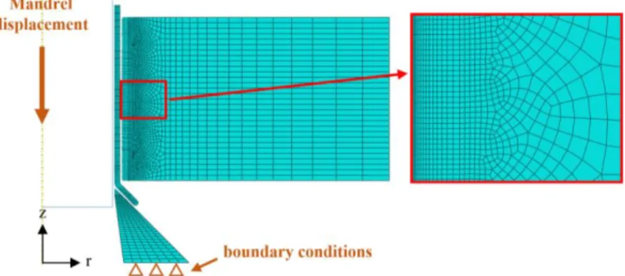
The Finite Elements Model (FEM) representing the cold expansion process developed with Abaqus by Achard [14] is taken over and adapted to the expansion in an alumi-num alloy part in order to generate a stress state in the part before reaming. The mod-el, presented in Figure 2, represents the workpiece and the different parts of the tool-ing : the conical mandrel, the sleeve and the jaw.
Fig. 2. Finite element model of the cold expansion process.
All the parts respect the dimensions imposed by the industrial specifications to ob-tain a final hole diameter of 6.35 mm and the thickness of the part is 6 mm. The simu-lated expansion rate is 6% in order to generate important residual stress fields in the part to better observe the influence of the reaming process in the rest of the study. The model is 2D axisymmetric, the part geometries, the loadings and the boundary condi-tions being compatible with this behavior hypothesis.
The steel mandrel can be considered and modeled as a rigid body in relation to the expanded aluminium part. The elastic behavior of the other three parts is considered as isotropic. The Young’s modulus (Table 1) are calculated on the basis of results from quasi-static characterizations and data used by Achard [14] in his work. The steel jaw which undergoes only weak plastic strain is modelled with a simple elastic constitutive law. The mechanical behavior of the steel sleeve and the aluminum workpiece which undergo severe plastic strain is described by elastoplastic constitu-tive laws. The plastic behavior of these parts is defined on the basis of results from uniaxial tensile strength tests. The material behavior of the workpiece is modelled by a kinematic hardening and the material behavior of the sleeve is modelled by an iso-tropic hardening.
Table 1. Material characteristics of the numerical model parts
Workpiece (AA 2024 T-351) Steel sleeve (15-5 PH) Steel jaw (AISI 301)
Young’s modulus (MPa) 67 800 194 501 205 000
Poisson’s ratio 0.33 0.272 0.29
Yield stress (MPa) 340 1024 /
In order to simulate the kinematics of the expansion, a displacement of -40 mm along the model axis of revolution (z) is imposed on the mandrel and the lower face of the jaw is fixed. Four contact areas are considered with a “surface-to-surface” dis-cretization method (mandrel/sleeve, sleeve/part, mandrel/jaw and jaw/sleeve).
The mesh, presented in Figure 3, is refined and composed of biquadratic elements with eight nodes (CAX8) in the areas of high plasticity (sleeve and hole edge area of the part). These elements which imply stress and strain calculations at 8 integration points per element allow providing accurate results that take the plastic phenomena into consideration well. The rest of the workpiece and the jaw are meshed with biline-ar elements with four nodes using a reduced integration (CAX4R). These elements which use a reduced integration imply a stress and strain calculation at only one inte-gration point by element. This allows saving computational time without losing accu-racy, the areas being slightly plastically deformed.
The calculation step corresponding to the simulation of the cold expansion process with the axial displacement of the mandrel is followed by a step simulating the with-drawal of the sleeve which is called “recovery”. During this step, the contacts be-tween the elements are deactivated and no loading is applied. This allows the part to achieve a new stress state.
The whole calculation is resolved according to an implicit time integration method.
2.2 Reaming simulation
The residual stress state obtained from the expanded part after the recovery step con-stitutes the initial stress state for the simulation of the reaming process.
Reaming is simulated by deactivating an elements band along the height of the part at the hole edge with a width of 0.35 mm. Two strategies for simulating the reaming process are compared. The first one is similar to the one implemented in Achard’s work [14]: all the elements of the reaming area are deactivated in the same calculation step. This modeling strategy allows to obtain the final residual stress state after ream-ing, it will be called “global reaming” in this study. The second strategy consists in deactivating the elements by several steps along the height of the part in order to sim-ulate the progressive feed of the tool during reaming. 19 calculation steps, each corre-sponding to the deactivation of around ten elements in the thickness are carried out (Figure 4). This allows obtaining the history of the stress state in the part during ream-ing. This will be called “progressive reaming”.
Thus, the two modelling strategies do not take into account the thermal effects oc-curring during reaming. The aim is to study only the impact of material removal on the stress state of the part which cannot be studied separately experimentally. Both modelling strategies should provide similar results. In the case of progressive ream-ing, the machining kinetics is exploited to define the calculation steps (height of deac-tivated elements and step duration). This time effect will fully make sense when an-other model involving progressive thermal loading will be implemented.
Fig. 4. Representation of the reaming area and the deactivated elements in the first calculation step
3 Results and discussion
During cold expansion simulation, residual stresses are generated in the part along the three directions: axial, radial and circumferential. Axial residual stresses are largely lower than radial and circumferential stresses, so this study focuses on the latter two.
Figure 5 shows the radial and circumferential stress states in the part after cold ex-pansion and global and progressive reaming simulations.
Fig. 5.Radial (a) and circumferential (b) stress states obtained in the part at the end of the cold expansion (1st column), global (2nd column) and progressive (3rd column) reaming simulations
These results show a non-homogeneous distribution of the residual stresses in the part after the cold expansion and reaming processes. The method for deactivating the elements in order to simulate the reaming process does not seem to affect the final stress state of the part.
The low influence of the reaming simulation on the residual stress state of the part can be noted. The radial residual stress field undergoes a progressive offset in the ra-dial direction during the reaming simulation. The two compression points on the entry and exit faces are slightly relaxed and the radial residual stress tends to homogenize in the thickness of the part. This relaxation could be related to the reduction of the axial strain at the hole edge on the entry and exit faces which is generated during the cold expansion process and which is sometimes called “volcano effect”. Concerning the circumferential residual stress field, this one is simply truncated in the reaming area.
Thus, a higher compressive stress state favoring a longer fatigue life is obtained at the hole edge.
The radial and circumferential residual stresses on the entry face and middle sec-tion of the part after cold expansion, global and progressive reaming simulasec-tions are shown in Figure 6. Radial stresses are compressive and have a characteristic profile. They cancel at the hole edge and at the free outer edge of the part. Circumferential stresses are of mixed nature with a compressive peak at the hole edge and then a ten-sile zone far from the hole.
Fig. 6. Evolution of radial (a) and circumferential (b) residual stresses along the entry face (1st column) and middle section (2nd column) of the part after cold expansion and global and
progressive reaming simulations
A relaxation of the radial residual stress is observed during reaming simulation with a 7 % reduction in the compressive peak on the entry face and 15 % on the mid-dle section. The modification of the circumferential residual stress is significant only on the entry face with a 6 % increase and a small offset of the compressive peak. Even though the level of residual stress changes during the reaming simulation, the heterogeneity of the stress state in the part remains. Indeed, the residual stress curves obtained after the cold expansion and reaming simulations present similar shapes. The changes in residual stress states are located in the hole edge area.
The results obtained with the two simulation strategies for reaming are identical. This confirms the equivalence of the two methods to obtain the final residual stress state of the part. The progressive reaming method seems nevertheless more interesting because it allows accessing to the intermediate stress states during the process. These useful results could be considered to gradually apply an equivalent
thermo-mechanical load in order to envisage a more realistic simulation of the reaming pro-cess.
The evolution of the residual stress fields during progressive reaming is studied in order to better understand the impact of the process on the material characteristics of the part. For this purpose, radial and circumferential stresses are measured on 9 ele-ments distributed according to the height and depth of the part. The location of these elements is described in Figure 7.
Fig. 7. Selected elements locating (center) in mm on the part after cold expansion simulation for
con-straint results reporting
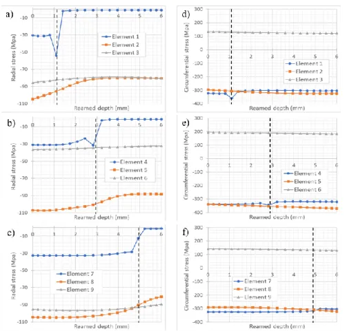
The residual stress evolution for each element is presented in Figure 8. On these graphs, a dotted line indicates the position of the elements where the stress results are measured in relation to the part depth.
The evolutions of the residual stress during the reaming process present different shapes depending on the elements considered. A stress balancing takes place gradually when the elements bands are deactivated for the elements located at the same level in the part thickness. This balancing is mainly carried out in the radial direction and intensifies by approaching the hole edge. Indeed, the elements located exactly at the hole edge (E1, E4 and E7) show a sudden stress evolution. The elements a little farther away from the hole edge (E2, E5 and E8) present a smoother evolution. Finaly, the elements very far from the hole edge (E3, E6 and E9) show almost linear evolutions.
The comparison of the numerical results obtained with experimental results is not yet possible. Indeed, it is impossible to implement experimentally the mechanism of material removal without involving thermal phenomena. Therefore, the results obtained are compared with previous numerical work as a first validation step. Kang [15] in his work develop a 3D FEM simulating the entire cold expansion process including hole expansion, recovery and finish reaming. A quarter of 2024-T351 aluminum part is modeled with a thickness of 6.35 mm and a final diameter hole of 7.26 mm. The reaming is simulated through the deactivation of mesh elements in the same way as in this study. Kang provides results of circumferential residual stress
along the entry face and the middle section. The result curves present a general shape similar to the one obtained in this study with a compressive peak at the hole edge and a tensile zone far from the hole. However, the shape of the compressive peak varies. This can be explained by the number of points considered for the plotting of the result graphs which depends on the mesh size. The residual stress levels obtained by Kang are of the same order of magnitude as those presented in this study. The differences may be due to the different dimensions used.
Thus, the model developed in this study seems relevant. Besides, it seems more interesting to gain in computing time compared to the 3D model.
Fig. 8.Evolution of radial (a,b,c) and circumferential (d,e,f) residual stresses during progressive reaming simulation
4 Conclusion
An enhancement in the reaming simulation is proposed compared to Achard’s simula-tion strategy [14]. This new simulasimula-tion which consists of progressively deactivating mesh elements allows to access to the history of the residual stress state of the part.
The results obtained show only a small change in the residual stress state of the part during the reaming simulation. It means the material removal has a weak influence on the residual stress state of the part. Thus, if a significant change in the residual stress state occurs during the reaming process, it should mainly be related to the thermo-mechanical phenomena. Therefore, a new strategy of reaming simulation according to the principle of applying a thermo-mechanical load as in Valiorgue’s works [13] is envisaged in order to take into account the mechanical cutting and thermal heating phenomena.
Nevertheless, the interpretation of the results emphasize a certain change of the residual stress state in the part during the reaming simulation especially at the hole edge area. It means to envisage a more realistic reaming simulation by applying an equivalent thermo-mechanical load on the hole edge, this one should not be dissociated from the material removal. Thereby, in the envisaged reaming simulation, the loading and the material removal will be applied synchronously and gradually in order to achieve an accurate final stress state in the part.
A reaming simulation on a pre-stressed part obtained after drilling simulation is al-so envisaged in order to study the evolution of the residual stress state in the hole edge zone during the whole machining process of the hole.
Finally, reaming tests with residual stress measurements in the part are envisaged in order to correlate the experimental measurements with numerical results. Residual stress measurements will be performed using the X-ray diffraction method. This tech-nique has the advantage of not being destructive but it is difficult to implement in the case of a textured material. This is the case for the studied specimens which have been rolled and which present elongated grains in the rolling direction. For that, a second technique which is destructive will also be used for residual stress measure-ments: the incremental hole drilling method.
References
1. Krishnakumar S., Ruby D.: Fatigue behaviour of aluminium alloy 7075 bolted joints treated with oily film corrosion compounds. Materials and Design 23, Elsevier (2002), https://doi.org/10.1016/S0261-3069(01)00060-7
2. Croccolo D., De Agostinis M., Vincenzi N.: Failure analysis of bolted joints: Effect of friction coefficients in torque-preloading relationship. Engineering Failure Analy-sis 18(1), 364-373, Elsevier (2011),
https://doi.org/10.1016/j.engfailanal.2010.09.015
3. Dang Hoang T., Herbelot C., Imad A.: Rupture and damage mechanism analysis of a bolted assembly using coupling techniques between A.E. and D.I.C. Engineering Structures 32(9), 2793-2803, Elsevier (2010),
https://doi.org/10.1016/j.engstruct.2010.04.048
4. Chakherlou T.N., Razavi M.J., Aghdam A. B., Abazadeh B.: An experimental inves-tigation of the bolt clamping force and friction effect on the fatigue behavior of alu-minum alloy 2024-T3 double shear lap joint. Materials & Design 32(8-9), 4641-4649, Elsevier (2011), https://doi.org/10.1016/j.matdes.2011.04.022
5. Lai M.O., Oh J.T., Nee A.Y.C.: Fatigue properties of holes with residual stresses. En-gineering Fracture Mechanics 45(5), 551-557, Elsevier (1993), https://doi.org/10.1016/0013-7944(93)90262-Q
6. Chakherlou T.N., Mirzajanzadeh M, Abazadeh B., Saeedi K.: An investigation about interference fit effect on improving fatigue life of a holed single plate in joints. Euro-pean Journal of Mechanics – A/Solids 29 (4), 675-682, Elsevier (2010), https://doi.org/10.1016/j.euromechsol.2009.12.009
7. Lanciotti A., Polese C.: The effect of interference-fit fasteners on the fatigue life of central hole specimens. Fatigue & Fracture of Engineering Materials & Structures, 28(7), 587-597 (2005), http://onlinelibrary.wiley.com/doi/10.1111/j.1460-2695.2005.00902.x/epdf
8. Ozdemir A.T., Hermann R.: Effect of expansion technique and plate thickness on near-hole residual stresses and fatigue life of cold expanded holes. Journal of Materi-als Science 34(6), 1243–1252, Springer (1999),
https://link.springer.com/article/10.1023/A:1004521309415
9. Lacarac V., Smith D.J., Pavier M.J., Priest M.: Fatigue crack growth from plain and cold expanded holes in aluminium alloys. International Journal of Fatigue 22 (3), 189-203, Elsevier (2000), https://doi.org/10.1016/S0142-1123(99)00126-7
10. Chakherlou T.N., Vogwellb J.: The effect of cold expansion on improving the fatigue life of fastener holes. Engineering Failure Analysis 10(1), 13-24, Elsevier (2003), https://doi.org/10.1016/S1350-6307(02)00028-6
11. Federal Aviation Administration: Assessment of residual stresses and hole quality on the fatigue behavior of aircraft structural joints 1. Washington DC: Office of research and technology development. (2009).
http://www.tc.faa.gov/its/worldpac/techrpt/ar0756v1.pdf
12. Girinon M.: Développement d’un modèle numérique sur l’étude de l’intégrité des sur-faces en perçage. PHD thesis (2017).
13. Valiorgue F., Rech J., Hamdi H., Gilles P., Bergheau J.M.: A new approach for the modelling of residual stresses induced by turning of 316L. Journal of Materials Pro-cessing Technology 191(1-3), 270-273, Elsevier (2007),
https://doi.org/10.1016/j.jmatprotec.2007.03.021
14. Achard V., Daidié A., Paredes M. and Chirol C.: Numerical modelling of the cold expansion process in mechanical stacked assemblies. Proceedings of International Joint Conference on Mechanical Design Engineering & Advanced Manufacturing (JCM2016), 501-508, (2016), http://dx.doi.org/10.1007/978-3-319-45781-9_50 15. Kang J. Johnson W.S., Clark D.A.: Three-dimensional finite element analysis of the
cold expansion of fastener holes in two aluminum alloys. Journal of Engineering Ma-terials and Technology 124(2), 140-145, ASME (2002),
![Fig. 1. Residual stress induced by machining (a) and cold expansion process (b) in a 2024-T3 alumi- alumi-num alloy part [11]](https://thumb-eu.123doks.com/thumbv2/123doknet/12255291.320373/3.892.281.606.550.712/residual-stress-induced-machining-expansion-process-alumi-alumi.webp)