HAL Id: hal-01426239
https://hal.univ-lorraine.fr/hal-01426239
Submitted on 6 Nov 2018
HAL is a multi-disciplinary open access
archive for the deposit and dissemination of
sci-entific research documents, whether they are
pub-lished or not. The documents may come from
teaching and research institutions in France or
abroad, or from public or private research centers.
L’archive ouverte pluridisciplinaire HAL, est
destinée au dépôt et à la diffusion de documents
scientifiques de niveau recherche, publiés ou non,
émanant des établissements d’enseignement et de
recherche français ou étrangers, des laboratoires
publics ou privés.
A new heat transfer analysis in machining based on two
steps of 3D finite element modelling and experimental
validation
Badis Haddag, Tchadja Kagnaya, Mohammed Nouari, Thierry Cutard
To cite this version:
Badis Haddag, Tchadja Kagnaya, Mohammed Nouari, Thierry Cutard. A new heat transfer analysis
in machining based on two steps of 3D finite element modelling and experimental validation. Heat and
Mass Transfer, Springer Verlag, 2013, 49 (1), pp.129–145. �10.1007/s00231-012-1069-8�. �hal-01426239�
A new heat transfer analysis in machining based on two steps
of 3D finite element modelling and experimental validation
B. Haddag •T. Kagnaya•M. Nouari• T. Cutard
Abstract Modelling machining operations allows esti-mating cutting parameters which are difficult to obtain experimentally and in particular, include quantities char-acterizing the tool-workpiece interface. Temperature is one of these quantities which has an impact on the tool wear, thus its estimation is important. This study deals with a new modelling strategy, based on two steps of calculation, for analysis of the heat transfer into the cutting tool. Unlike the classical methods, considering only the cutting tool with application of an approximate heat flux at the cutting face, estimated from experimental data (e.g. measured cutting force, cutting power), the proposed approach con-sists of two successive 3D Finite Element calculations and fully independent on the experimental measurements; only the definition of the behaviour of the tool-workpiece couple is necessary. The first one is a 3D thermomechanical modelling of the chip formation process, which allows estimating cutting forces, chip morphology and its flow direction. The second calculation is a 3D thermal model-ling of the heat diffusion into the cutting tool, by using an adequate thermal loading (applied uniform or non-uniform heat flux). This loading is estimated using some quantities obtained from the first step calculation, such as contact pressure, sliding velocity distributions and contact area. Comparisons in one hand between experimental data and
the first calculation and at the other hand between mea-sured temperatures with embedded thermocouples and the second calculation show a good agreement in terms of cutting forces, chip morphology and cutting temperature. List of symbols
Cutting parameters Vc Cutting speed (m/min)
f Feed rate (mm/tr) ap Depth of cut (mm) jr Approach angle (!) co Tool-rake angle (!) ks Inclination angle (!) ao Clearance angle (!)
Fc Cutting cut force component (N) Ff Feed force component (N) Fp Depth of cut force component (N) FR Resultant cutting force (N) Mechanical quantities
r Cauchy stress tensor (MPa)
fv Body force density vector (N/m3) €
u Acceleration vector (m/s2)
q Material density (kg/m3)
E Young modulus (GPa)
v Poisson’s ratio
A Initial uniaxial tension stress at reference equivalent plastic strain-rate and reference temperature of the workmaterial (MPa)
B Strain hardening parameter of the workmaterial
(MPa)
n Strain hardening exponent parameter of the
workmaterial
C Strain-rate sensitivity parameter of the workmaterial
B. Haddag (&) ! T. Kagnaya ! M. Nouari
Laboratoire d’E´ nerge´tique et de Me´canique The´orique et Applique´e, Universite´ de Lorraine, LEMTA CNRS-UMR 7563, Mines Nancy, GIP-InSIC, 27 rue d’Hellieule, 88100 St-Die´-des-Vosges, France
e-mail: badis.haddag@insic.fr T. Kagnaya! T. Cutard
Mines Albi, ICA (Institut Cle´ment Ader), Universite´ de Toulouse, Campus Jarlard, 81013 Albi cedex 09, France
m Temperature sensitivity parameter of the workmaterial
"
ep von Mises equivalent plastic strain
_"ep von Mises equivalent plastic strain-rate
_"e0 Reference equivalent plastic strain-rate
"
r von Mises equivalent stress (MPa)
rn Normal friction stress (MPa)
sf Shear friction stress (MPa)
l Friction coefficient
smax Shear stress limit (MPa)
"sf Average sliding stress at the tool-chip interface
(MPa)
"_c Average sliding velocity at the tool-workpiece interface (m/s)
s(x,y) Local sliding stress at the tool-workpiece interface (MPa)
_
c x; yð Þ Local sliding velocity at the tool-workpiece interface (m/s)
Ux Displacement along the x axis
Uy Displacement along the y axis
Uz Displacement along the z axis
Thermal quantities
T Temperature (!C)
T0 Reference ambient temperature (!C)
Tm Workmaterial melting temperature (!C)
Tenv Environment temperature (!C)
Ttool Tool temperature (!C)
Thold Toolholder temperature (!C)
Tint-w Interface workpiece temperature (!C) Tint-t Interface tool temperature (!C)
k Thermal conductivity (W/m/!C)
cp Specific heat capacity (J/kg/!C)
a Thermal expansion (lm/m/!C)
gp Plastic work conversion factor
(Taylor-Quinney factor)
ff Fraction of the friction energy conducted into
the tool
h Heat transfer coefficient for the
tool-wokpiece interface (kW/m2/!C) henv-tool Heat transfer coefficient for the
tool-environment interface (W/m2/!C) hhold-tool Heat transfer coefficient for the
toolhorder-tool interface (W/m2/!C)
_qv Volumetric heat generation in the
workmaterial (W/m3)
_qp Volumetric heat generation due to plastic
work (W/m3)
_qf Frictional heat flux at the tool-workpiece
interface (W/m2)
_qc Heat conduction flux at the tool-workpiece
interface (W/m2)
_q!tool Heat flux going into the tool at the tool-workpiece interface (W/m2)
_q!workpiece Heat flux going into the workpiece at the tool-workpiece interface (W/m2)
_q!env Heat flux at the tool-environment interface
(W/m2)
_q!hold Heat flux at the toolholder-tool interface (W/m2)
"_q!tool Applied uniform heat flux on the tool rake face (W/m2)
_q!toolðx; yÞ Applied non-uniform heat flux on the tool
rake face (W/m2)
1 Introduction
In machining processes, the development of accurate models to estimate heat exchange, cutting forces and tool wear has been the subject of particular attention in scien-tific community. Analytical, numerical or hybrid models are developed for the analysis of different machining pro-cesses. The efficiency of each approach is related to the physical quantities that can be estimated, and also to the possibility to use such quantities to optimize or to improve the cutting operation (e.g. increasing tool life, enhancing productivity or reducing lubrication, etc.). Analytical models are generally based on several assumptions (geometrical simplifications, simple boundary conditions, simplified tool-workpiece configuration, etc.) which allow obtaining a rapid estimation of some thermomechanical quantities. Some example of such developments can be found in [1–9]. Besides, numerical models are more effi-cient for machining problems where complex tool
geom-etry and/or tool-workpiece configuration should be
considered. Finite Element [10–18], Difference Element [19, 20] and more recently Smoothed Particle Hydrody-namics [22] methods are an example of such approaches used in this case. During these last years, it seems that the Finite Element Method (FEM) is the widely used approach; while up to 90th analytical approaches are the main pro-posed analyses. In fact, the FEM allows treating the chip formation process with few assumptions, particularly when cutting process should be treated under the 3D configura-tion (non-orthogonal cutting condiconfigura-tions), as in the present work. However, compared to the analytical approaches, the high computation time remains the weak point of the FE approaches.
Cutting process is modelled considering either the tool-workpiece couple, as in [10–22], or only the cutting tool with adequate thermomechanical loading, as in [23–36]. For the first case, chip formation process is globally ana-lysed. In several research works the problem is treated in
orthogonal cutting configuration, with analytical, numerical or hybrid models. The main quantities estimated are the cutting force, the chip morphology and tool-chip interface characteristics (contact length/area, contact pressure, interface temperature…). Simulations with FEM in 3D case are performed recently thanks to advanced developments in remeshing techniques in commercial FE codes, like DeformTM [37] and AbaqusTM [38], used in the present work. For the second case, since the integrity of cutting tools during machining is of particular importance (improving tool life, machined surface quality…) analysis of its behaviour is widely investigated. The developed models consider the cutting tool, with the definition of the thermomechanical loading, to analyse its behaviour during machining. One of the critical point of this analysis, irre-spective of the approach followed (analytical, numeri-cal…), is the definition of the boundary conditions, particularly the adequate thermomechanical loading in the active zone of the tool (tool-workpiece contact zone). Indeed, interface contact pressure, sliding velocity, contact area as well as some physical parameters involved in the constitutive equations (e.g. friction heat partition and interface heat transfer coefficients) should be well defined to estimate the thermomechanical loading of the cutting tool. These quantities are generally estimated from experi-mental measurements, combined with some analytical developments. Chang [30] developed an analytical– numerical model for heat transfer into the tool. The model takes into account the geometry of the tool active zone of the insert to determine the friction contact area, and the friction force, in order to deduce the applied heat flux to the cutting tool (insert). Stephenson et al. [26] developed an analytical model to predict the cutting tool temperature under transient conditions. The thermal loading at the contact face of insert is treated as a spatially uniform plane heat source function of cutting time. The contact area is defined from experimental machining tests. The model is based on an analytical solution for the temperature in a rectangular insert subjected to a piecewise constant heat flux. Different thermal boundary conditions are applied to the insert to show its impact on the tool-chip interface temperature. Liu et al. [25] studied the temperature field in a milling insert with complex groove. Using analytical model and one measured temperature at an embedded thermo-couple in the insert, they defined the temperature evolution with cutting time at several points at the tool-chip interface. These temperatures are then used in a developed FE model as thermal boundary conditions. Several authors developed the same modelling strategy (e.g. [23–36]), but in all treated problems a uniform applied heat flux is considered, which is not true in reality, as it can be seen in this work.
The objective of this work is the combination between the approach using the tool-workpiece couple for chip
formation process analysis and that treating the cutting tool separately, with adequate thermomechanical loading. This allows to easily analysing the heat diffusion into the insert without using any measured quantities, like cutting force or cutting power for example. The modelling strategy is developed in the context of a fully 3D FEM and focused on the thermomechanical behaviour of the tool-workpiece couple. For experimental validation, a turning operation is considered. The approach allows giving the main physical quantities characterizing the cutting process exclusively from modelling, so experimental data are used only for the validation purpose. First of all, the experimental procedure is described and some experimental results are given for modelling validation. Then, the main constitutive equations for the modelling are presented. The two-steps FE-based model is then developed with the description of the chip formation process analysis (first step), followed by the modelling of heat diffusion into the insert (second-step). Finally, the obtained results from each calculation have been compared with the experimental data.
2 Experimental aspects 2.1 Experimental setup
The experimental setup consists of an instrumented turning operation using dynamometer table (Kistler" table, type 9257B) and thermocouple system (Actarus"[39,40]), for cutting force components and temperature measurements, respectively. Note that different temperature measurement systems can be used in machining, as shown in [39–44]. The tool-workpiece configuration, machining device and exper-imental setup used for measurements are illustrated in Fig.1a–c, respectively. The cutting configuration of the tool-workpiece couple is defined by the following cutting angles: approach anglejrequal 90!, tool-rake coand incli-nationksangles equal 0!, and clearance angle equal 7!, as shown in Fig.1a. The cutting condition that has been taken for the numerical analysis and validation is as follows: • cutting speed: Vc= 250 m/min,
• feed rate: f = 0.1 mm/tr, • depth of cut: ap = 1.1 mm.
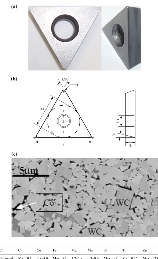
The cutting tool is a triangular uncoated insert, of a WC-6 %Co material (cemented tungsten carbide with 6 % of cobalt as binder phase), designated by TCMW16T304. The insert and its dimension characteristics are shown, respectively, in Fig.2a, b, the microstructure of the insert material is shown in Fig.2c, while the chemical compo-sition is given in Table 1.
The workpiece is a bar of the ferrite-perlite steel AISI 1045, with diameter of 90 mm, commonly used in industry
(aerospace, automotive, mechanical). The microstructure of this material is shown in Fig. 3 and its chemical com-position is given in Table 2.
To measure the cutting temperature at two points close to the tool-rake face during the cutting process, two chromel/ alumel thermocouples (K-type) of 0.25 mm diameter are used. The operating temperature is in the range of -100 to 1,100!C, and the time response is about 100 ms. The Ther-mocouples calibration is carried using the linearization method. The thermocouples are embedded, thanks to a high conductive adhesive (AGAR SILVER), in 0.3 mm diameter
holes, as shown in Fig.4a, obtained by means of EDM (Electrical Discharge Machining). The location of the ther-mocouples in the insert is shown in Fig.4b. The temperatures (TC1 and TC2) are directly recorded during the machining test with TWS software developed by Actarus"company in [39,
40], simultaneously with cutting force components recording. 2.2 Experimental data
From the machining test, cutting force components are measured, as reported in Table3. For the cutting condition
(a)
(b)
(c)
Fig. 1 a Tool-workpiece configuration, b machining device, and c experimental setup used for the analysis [23]
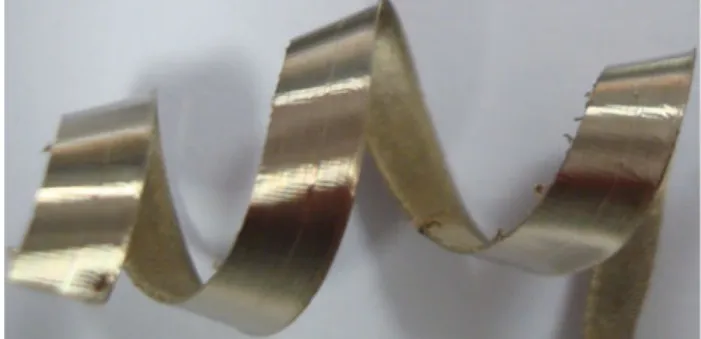
used a continuous chip without segmentation is obtained, as shown in Fig.5.
From the temperature measurement system, the tem-perature evolution is measured during machining, as shown
in Fig.6. High temperature level is obtained in TC1, as expected, since it is the closest to the tool-chip interface in the cutting configuration used here. After 5 s the cutting operation is stopped, so the temperature at thermocouples
(b)
(a)
S D D1 L 60° 7° r(c)
Fig. 2 a Insert TCMW16T304, b dimension characteristics (L = 16.5 mm, D = 9.53 mm, D1 = 4.4 mm, S = 3.97 mm), and c SEM image of a polished surface inside the carbide (6 wt% Co) tool [23]Table 1 Chemical composition
(wt%) of the WC-6Co [23] C Cr Cu Fe Mg Mn Si Ti Zn Balanced Max. 0.1 3.8–4.9 Max. 0.5 1.2–1.8 0.3–0.9 Max. 0.5 Max. 0.15 Max. 0.25
decreases rapidly since there is no contact at the tool-workpiece interface (no heat generation by friction and plastic deformation responsible of the tool heating).
3 Constitutive equations for modelling
The modelling of the chip formation process is generally performed by considering the tool-workpiece couple. Only the vicinity of the cutting zone is considered in the numerical model. From the continuous media mechanics, each material point in the tool-workpiece couple should satisfy simultaneously (and at any time) the following mechanical and thermal balance equations:
divr þ fv¼ q€u ð1Þ
kr2
T & qcpT þ _q_ v¼ 0 ð2Þ
where r the Cauchy stress tensor, fvthe body force density vector,u the acceleration vector, T the temperature,€ q the material density,k the thermal conductivity, cpthe specific heat capacity, and _qvthe volumetric heat generation.
The last balance equations are strongly coupled when they are applied to the tool-workpiece couple in machining, since the Cauchy stress tensor r depends on the tempera-ture T via the material behaviour laws (see the following section about constitutive model). Also in the thermal balance Eq. (2), volumetric heat generation _qv in the
cut-ting zone is mainly due to the plastic work, so T depends on r and plastic strain-rate. The different non-linearities (geometrical, behaviour and contact) make the analytical resolution of the two equilibrium Eqs. (1) and (2) practi-cally impossible in practice, especially in three-dimen-sional configuration (oblique cutting), as considered in the
present work. A numerical approach, like the Finite Element Method (FEM), is generally necessary to solve this system of equations.
3.1 Constitutive model
To analyse the chip formation process, a Johnson–Cook model [45] has been used to represent the thermo-visco-plastic behaviour of the workmaterial, where the flow stress is given as follows: " r ¼ A þ Bð"ep Þn ½ ( |fflfflfflfflfflfflfflffl{zfflfflfflfflfflfflfflffl} Hardening 1þ C ln _"e) " # |fflfflfflfflfflfflfflffl{zfflfflfflfflfflfflfflffl} Viscosity 1& T)m ½ ( |fflfflfflfflffl{zfflfflfflfflffl} Softening
with _"e)¼_"e
p
_"e0
and T)¼ T & T0 Tm& T0
ð3Þ
where A, B, C, m and n are the material parameters,"ep the
von Mises equivalent plastic strain, _"ep the von Mises
equivalent plastic strain rate, _"e0 the reference equivalent Fig. 3 Microstructure of the ferrite- perlite steel AISI 1045 [23]
Table 2 Chemical composition (wt%) of the AISI 1045 steel [23] C Si Mn P S Cr Ni Mo Cu 0.45 0.22 0.66 0.027 0.032 0.26 0.15 0.02 0.18
(a)
TC2
200 µm(b)
TC2
TC1
d
y1d
x2d
x1d
y2TC1
Fig. 4 a Insert with holes for thermocouples, and b location of the thermocouples (TC1: dx1= 1.6 mm, dy1= 0.5 mm, TC2:
plastic strain rate, Tmand T0are, respectively, the material melting temperature and the reference ambient temperature. As the mechanical behaviour is affected by temperature (softening effect), the mechanical plastic work generates heat flux which result in temperature rise. The heat gen-eration due to this phenomenon is described by the fol-lowing relationship:
_qp¼ gpr : _"e" p ð4Þ
where gp is the plastic work conversion factor (Taylor-Quinney factor).
3.2 Interface behaviour
The contact behaviour of the tool-workpiece interface is defined by the relationship between the normal friction stressrnand the shear friction stresssf, as follows:
sf ¼ lrn if lrn\sMax
sMax if lrn* sMax
$
ð5Þ where l is the friction coefficient and smax is the shear stress limit, considered equal to the initial plastic flow shear stress of the workmaterial (AISI 1045 steel), since its ductility is much lower compared to that of the cutting tool (cemented tungsten carbide WC-6Co).
The friction process at the tool-workpiece interface generates a heat which can be evaluated by the following relation:
_qf ¼ gfsfc_ ð6Þ
wherec is the relative sliding velocity, s_ fthe friction stress given by Eq. (5),gfthe frictional work conversion factor. By assuming that all the frictional work is converted into heat,gf= 1 is often considered.
The mechanical plastic work of the chip affects heat exchange at the tool-workpiece interface. To take into account this energy in the heating of the tool, the heat conduction flux _qcis introduced, so the heat balance at the
interface can finally be written as follows: _q!tool¼ ff_qf þ _qc
_q!workpiece¼ 1 & ff
% &
_qf & _qc ð7Þ
with
_qc¼ hðTint&w& Tint&tÞ ð8Þ
where _q!tool is the heat flux transmitted to the tool,
_q!workpiece is the heat flux going into the workpiece
(calo-rific energy mainly evacuated by the chip), ffis the fraction of the friction energy conducted into the tool (heat partition coefficient), h is the interface heat transfer coefficient, while Tint-w and Tint-t are temperatures, respectively, of workpiece and tool at the tool-workpiece interface.
4 Two-steps finite element modelling 4.1 Motivation
The challenge in numerical modelling of machining pro-cesses is to obtain the main physical quantities character-ising the process in reasonable computational time with acceptable accuracy. In order to analyse the chip formation process in a non-orthogonal cutting configuration (oblique cutting), a FEM is widely used, since it allows treating the
Table 3 Average cutting force components and resultant force for the cutting condition: Vc= 250 m/min, f = 0.1 mm,
ap = 1.1 mm
Resultant cutting force, FR(N)
Cutting (tangential) force, Fc(N)
Depth (radial) force, Fp
(N)
Feed (axial) force, Ff
(N)
493 366 102 314
Fig. 5 Experimental chip morphology: continuous chip without segmentation 0 50 100 150 200 250 300 350 400 0 1 2 3 4 5 6 Thermocouples temperature [°C] Cutting time [s] TC1 Exp TC2 Exp
Fig. 6 Temperature evolution at thermocouples TC1 and TC2 during machining; after 5 s cutting is stopped
problem in 3D case with fewer simplifying assumptions, unlike analytical approaches. However, one of the major inconvenient of the FEM is the high CPU time necessary to obtain all quantities. In fact, simulation of the chip for-mation process in 3D case over few milliseconds of the cutting time, as it can be confirmed in Sect. 5.1, necessi-tates few days of CPU time to obtain stabilized cutting force, chip morphology and its flow direction. But heat diffusion into the cutting tool necessitates calculation over few seconds of the cutting time; see Fig. 6b for the tem-perature evolution at the thermocouples. Clearly, it is not possible to obtain with the same FE calculation and in reasonable CPU time all thermomechanical quantities characterising the process.
As illustrated in Table4, new idea is developed which consists to decompose the problem on two successive calculations (two-steps FE-based modelling):
• The first one is a fully 3D thermomechanical modelling of the chip formation process; which allows estimating all components of the cutting force, chip morphology as well as the chip flow direction, and other quantities necessary for the second-step of calculation.
• The second one is a fully 3D thermal modelling of the heat transfer into the cutting tool, using some quantities obtained at the first-step of calculation, like tool-chip interface pressure, sliding velocity distributions as well as contact area.
In order to illustrate the robustness of the proposed approach, a comparison between experimental data (cutting
force components, chip morphology) and temperature measured by the two thermocouples, embedded in the tool close to the active zone of the cutting face, is performed in Sect.5.2.
4.2 First step: modelling of the chip formation process The 3D FE model, defined for the first step calculation, is shown in Fig.7. The FE model for turning process consists to position the insert against the machined material zone, representing the workpiece; which is affected by the cut-ting process. Only a part of the insert is considered, as highlighted in Fig.7a, including the cutting face and thermocouple holes. The cutting configuration, as shown in Fig.7b, corresponds to the experimental one (see Fig.1a). Physical and thermal boundary conditions are defined. In the model, the workpiece is fixed at the bottom and lateral faces and cutting velocity is applied to the cutting tool, as shown in Fig.7b. While thermal boundary condi-tions take into account heat exchange with environment for all surfaces of the insert and workpiece, except at the tool-workpiece interface where equations listed in Sect.3.2are considered. The initial temperature for the tool-workpiece couple is taken equal to 20!C.
The workpiece and tool are meshed with tetrahedron finite element of Deform code [37], a coupled linear dis-placement-temperature 4 nodes element, with about 290,000 elements for the insert and 156,000 elements for the workpiece. The initial mesh of the tool-workpiece couple and the mesh refinement of the cutting zone are
Table 4 Illustration of the two-steps finite element modelling strategy
Chip formation process Data transmission Heat diffusion into the insert
c
V
f
ap
Simulation over a short cutting time (few milliseconds):
Stabilized cutting force Stabilized chip morphology Chip flow direction
Data for second step: Tool-chip contact area Contact pressure distribution Sliding velocity
Purely thermal simulation over a long cutting time (few seconds):
Heat flux and temperature fields Temperature at the thermocouples
shown in Fig.8a and b respectively. A minimum element size (about 10lm) is taken in the insert (at the active cutting face) and chip zones. This value is chosen after some numerical tests to find a good compromise between result accuracy and reasonable CPU time.
4.3 Second step: modelling of the heat transfer into the insert
The second step consists to model the heat transfer into the cutting tool. The insert is represented in totality unlike in the first-step calculation, where only the active part of the
(a)
(b)
0 x U = 0 y z U =U =0
x zU
=
U
=
cV V
=
(c)
ap
f
cV
Fig. 7 First-step FE model for the simulation of the chip formation process [37]: a highlighting of the considered part of the cutting tool, b initial tool-workpiece configuration with boundary conditions and c highlighting of the cutting zone
Fig. 8 Mesh of the tool-workpiece couple, with mesh refinement of the cutting zone [37]: a initial tool-workpiece mesh and b highlighting the mesh refinement of the cutting zone
insert is considered. In order to compare to experimental temperature, holes machined in the insert to introduce thermocouples are also considered in the model. Figure9
shows the mesh of the insert with DC3D4 FE of Abaqus library, a 4 nodes linear heat transfer tetrahedron element (more than 390,000 elements).
To represent the real heat diffusion into the insert, adequate thermal boundary conditions should be consid-ered. The temperature measured by the two thermocouples will be used to validate the heat diffusion model. As shown
Fig. 9 Mesh of the insert, with mesh refinement of the cutting zone [38]: a mesh of the cutting tool and b highlighting the mesh refinement of the cutting zone
(a)
(b)
(c)
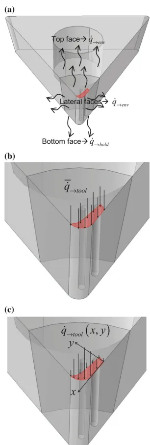
Fig. 10 Thermal boundary conditions: a heat exchange with envi-ronment and toolholder, b applied uniform and c non-uniform heat flux at the tool-chip contact face
in Fig. 10three types of boundary conditions are applied to the insert:
1. heat exchange with environment (top and lateral
faces), see Fig.10a:
_q!env¼ henv&toolðTenv& TtoolÞ ð9Þ
2. heat exchange with the tool holder (bottom face), see Fig.10a:
_q!hold¼ hhold&toolðThold& TtoolÞ ð10Þ
3. applied heat flux at the tool-chip contact face, see Fig.10b and c. Here, only the heat due to the friction is considered, and two cases are defined:
i. the first one corresponds to apply a uniform heat flux, see Fig.10b:
"_q!tool¼ ff:_qf ¼ ff:gf:"sf:"_c ð11Þ
where "sf and "c are, respectively the average values of_
sliding stress and sliding velocity at the tool-chip interface, computed from the first-step model (chip formation process).
ii. the second one corresponds to apply a
non-uniform heat flux, see Fig.10c, by taking into account the non-uniform contact pressure distri-bution at the tool-chip interface, which is obtained from the first-step model, so:
_q!toolðx; yÞ ¼ ff:_qf ¼ ff:gf:sfðx; yÞ:_c x; yð Þ ð12Þ
wheresf(x,y)andc x; y_ð Þ are local values of the sliding stress and sliding velocity at the tool-chip contact face, respec-tively, computed from the first-step model.
From the thermal boundary conditions, two cases are defined to analyse heat diffusion into the insert: applied
uniform and non-uniform heat flux at the tool-chip contact face. The comparison between the two cases with respect to measured temperature by thermocouples will be given in Sect.5.2.
4.4 Material and interface parameters
Basic physical properties of the workpiece and tool mate-rials are given in Table5, and behaviour parameters of the workpiece material are given in Table6. The parameters of the tool-workpiece interface model are given in Table7, while the heat transfer parameters involved in the second-step model are given in Table8.
5 Results and discussion
As described in Sects.4.2and4.3, from each step of cal-culation some pertinent results can be obtained. Here, these results are discussed in terms of the chip formation process (cutting force, chip morphology and chip flow direction) and heat transfer into the cutting tool, with comparison with experimental results, given in Sect.2.2.
5.1 Analysis of the chip formation process
From the first-step FE model the chip formation process is analysed. Chip morphology exhibits the signature of the correct behaviour taken in the simulation. So Fig.11
illustrates the chip morphology obtained from the numer-ical simulation. The continuous chip is well reproduced as in experiment as well as its flow direction.
As shown in Fig.12, predicted cutting force compo-nents (Fc, Ffand Fp) and resultant (FR) indicate that there
Table 5 Basic mechanical and thermal properties of workpiece and tool [23] Physical parameter Workpiece (AISI 1045) Tool (WC–Co) (kg/m3) 8,000 14,900 E (MPa) 210.103 600 v 0.33 0.22 cp(J/kg/!C) cp= 0.504T ? 420 222 k (W/m/!C) k = -0.0281T ? 52.61 20 B T B 300: k =-0.1131T ? 120.03 300 B T B 500: k =-0.005T ? 87.5 500 B T B 600: k =-0.02T ? 95 a (m/m/!C) 12.10-6 9 gp 0.9 9 Tm(!C) 1,460 9 T0(!C) 20 20
Table 6 Johnson-Cook thermo-visco-plastic parameters of workpiece—first-step model [46]
A (MPa) B (MPa) n C m
553.1 600.8 0.234 0.0134 1
Table 7 Workpiece-tool interface parameters—first-step model [23,37]
l smax(MPa) h (W/m2/!C) ff
0.6 No limit 45.103 0.1
Table 8 Heat transfer parameters—second-step model [23,37] Tenv(!C) Thold (!C) henv-tool (W/m2/!C) hhold-tool (W/m2/!C) ff 20 20 90 5.103 0.13
are some differences with experimental ones. In fact, the feed force is underestimated by calculation, since in the numerical model a circular movement is applied to the insert, while in real machining process helical movement occurs. This means that a reaction force in feed direction, in reality, is due at the same time to the permanent movement of the insert in the feed direction and the chip formation. In the numerical model, this axial movement is not taken correctly (the insert is positioned in fixed feed and circular movement is applied), so the feed reaction force is due only to the chip formation. While the depth reaction force is well reproduced, since the kinematics in the radial direction is well taken by the numerical model (there is no movement in the radial direction during the chip formation process as in real configuration of machining). As reported in Table 9, globally the average cutting force components and resultant are comparable to the experimental ones. From the performed simulation, contact pressure distribution at the active zone of the insert is also estimated, as shown in Fig.13.
To perform this first-step calculation in Deform FE soft-ware, with optimal mesh resolution (more than 446,000 elements for the tool-workpiece couple), 8 days are neces-sary. It was shown that temperatures given by thermocouples
Fig. 11 Simulated continuous chip and its flow direction: comparison with the experimental chip 0 100 200 300 400 500 600 700 800 0 0,0005 0,001 0,0015 0,002
Cutting force components and resultant [N]
Cutting time [s]
Fc - exp Ff - exp Fap - exp Ftot - exp Fc - num Ff - num Fap - num Ftot - num
Fig. 12 Experimental versus numerical cutting force components and resultant
Table 9 Comparison between experimental and numerical values of average cutting force components and the resultant force
Force (N) Experiment Numerical
Fc 366 480
Ff 314 205
Fp 102 104
stay at the initial value of 20!C (see Fig.14), so no signif-icant heat diffusion occurs during the cutting duration (about 1.8 ms). This implies that it is not possible to obtain the temperature evolution in the bulk of the insert and at the thermocouples with reasonable CPU time. However, using some quantities obtained from this first-step calculation and additional adequate thermal boundary conditions, as described in Sect.4.3, allows simulating heat diffusion into the insert over a few seconds in reasonable CPU time. Indeed, simulation of the heat transfer into the tool by solving only the heat balance Eq. (2) by EF takes much less com-puting time compared to solving the problem dealt with the first thermomechanical model, where mechanical and ther-mal balance Eqs. (1) and (2) are strongly coupled.
5.2 Analysis of the heat transfer into the cutting tool The two cases of the heat diffusion into the insert defined in Sect. 4.3, which correspond to applied uniform and
Fig. 13 Contact pressure distribution at the active face of the insert obtained from the first-step FE calculation
Fig. 14 Temperature distribution in the insert obtained from the first-step FE calculation: thermocouples are not affected
Fig. 15 a Contact area obtained from the first-step FE model, and b reproduced at the active zone of the insert for the heat diffusion analysis with the second-step model
non-uniform heat fluxes at the tool area in contact with the chip, are analysed here. To perform such simulations, contact pressure and sliding velocity distributions as well as contact area are extracted from the first-step calculation. As shown in Fig. 15, the geometry of the contact area (Fig.15a) is reproduced in the insert (Fig.15b) to apply the tool-chip heat flux.
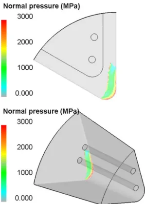
From the performed heat diffusion simulations, the heat flux and temperature distributions in the insert at any time are obtained, Fig.16. The heat flux and temperature fields are clearly affected by the applied heat flux. For the applied non-uniform, heat flux temperature is highly localized at the cutting edge (in the sticking region), while for applied uniform heat flux temperature is quasi-uniform at the contact face.
The comparison between measured and numerical temperature evolution at the thermocouples is given in Fig.17. It can be observed from Fig.17a that the applied uniform heat flux fails to fit the measured temperatures at the two thermocouples. On the other hand in Fig.17b, the
applied non-uniform heat flux, which better corresponds to the actual heat exchange at the tool-chip interface in machining, gives the best result, especially for the tem-perature evolution on the thermocouple TC1. However in these two cases, the temperature evolution on the thermo-couple TC2 is poorly reproduced (underestimated). This is due to the underestimation of the contact area in the first-step calculation. As shown in Fig.15, the thermocouple TC1 is closer to the contact face than the thermocouple TC2, so temperature at the TC2 will be more affected by the error on the estimation of this contact area and its shape.
6 Conclusions
To analyse the heat diffusion in complex machining operation, a new approach based on two steps of 3D FE modelling has been developed. The proposed strategy uses tool-chip interface parameters such as contact pressure,
Fig. 16 Heat flux and temperature distributions in the insert at cutting time equal 5 s: a heat flux and b temperature fields for applied uniform heat flux, c heat flux and d temperature fields for applied non-uniform heat flux
sliding velocity and contact area to estimate the applied heat flux at the cutting face of the insert. The interface parameters are extremely difficult to estimate only by experimental means because of the high thermomechanical loading applied to the tool-chip interface during machining (high contact pressure, high temperature, intense friction, etc.). From the performed modelling several concluding remarks can be drawn:
1. The chip formation process simulated with the first-step model allows obtaining stabilized cutting forces, accurate chip morphology as well as chip flow direc-tion. Different tool-chip interface parameters can also be estimated. It has been shown that the predicted feed force is underestimated compared to the experimental one. This is due to the relative helical motion between the tool and workpiece, which was represented by circular motion in the first-step FE model.
2. Numerical simulation of the chip formation process over few milliseconds (about 1.8 ms) of the cutting time with the first-step FE model is achieved in about 8 days. It has been shown that this is not sufficient to obtain heat diffusion into the insert up to embedded
thermocouples in reasonable CPU time only with this thermomechanical calculation.
3. Using contact pressure, interface sliding velocity and contact area, obtained from the first-step calculation, has allowed estimation of applied thermal load at the tool rake face used in the second-step FE model. 4. The fully thermal analysis performed with the
second-step FE model allows obtaining the temperature and heat flux fields in the insert and their evolution over few seconds of cutting time (about 5 s). This time corresponds to the cutting duration of the machining test.
5. The applied heat flux at the contact zone of the insert is a critical for a good prediction of the heat diffusion into the insert. So using applied uniform or non-uniform heat flux has given different temperature and heat flux fields.
6. The temperature at TC1 is well predicted using the applied non-uniform heat flux. However, the temper-ature at TC2 is underestimated in the two cases (uniform and non-uniform applied heat fluxes). This is attributed to the underestimation of the contact area by the first-step FE model. Since the second thermocouple is more distant from the tool-chip interface, where heat generation by friction and plastic deformation occurs, predicted temperature at TC2 is less than the measured one. Improvement of the first-step FE calculation would give a more accurate temperature at TC2. However the gap between predicted and experimental temperatures would be much reduced if embedded thermocouples are closer to the cutting face. But in practice this can weaken the cutting tool if holes of thermocouples are closest to the cutting face.
Finally, it can be concluded that the proposed original strategy allows estimating non-uniform distributions of the tool-workpiece interface parameters, which are extremely difficult to obtain by experimental means. The critical point in the proposed approach lies in the first thermomechanical calculation, which determines de reliability of the second thermal calculation. However the possibility to perform calculations in reasonable time has been highlighted in this study.
References
1. Molinari A, Moufki A (2008) The Merchant’s model of orthog-onal cutting revisited: a new insight into the modelling of chip formation. Int J Mech Sci 50:124–131
2. Ozlu E, Budak E, Molinari A (2009) Analytical and experimental investigation of rake contact and friction behaviour in metal cutting. Int J Mach Tools Manuf 49:865–875
0 50 100 150 200 250 300 350 400 0 0 1 2 3 4 5 6 Thermocouples temperature [°C] Cutting time [s]
Applied Uniform Heat Flux
TC1 Num TC1 Exp TC2 Num TC2 Exp 0 50 100 150 200 250 300 350 400 1 2 3 4 5 6 Thermocouples temperature [°C] Cutting time [s]
Applied Non-Uniform Heat Flux
TC1 Num TC1 Exp TC2 Num TC2 Exp
(a)
(b)
Fig. 17 Experimental temperature versus numerical temperature evolution at the thermocouples
3. Xie JQ, Byoumi AE, Zbib HM (1996) A study on shear banding in chip formation of orthogonal machining. Int J Mach Tools Manuf 36:835–847
4. Pawade RS, Sonawane HA, Joshi SS (2009) An analytical model to predict specific shear energy in high-speed turning of Inconel 718. Int J Mach Tools Manuf 49:979–990
5. Moufki A, Molinari A, Dudzinski D (1998) Modelling of orthogonal cutting with a temperature dependent friction law. J Mech Phys Solids 46(10):2103–2138
6. Grzesik W (2006) Composite layer-based analytical models for tool–chip interface temperatures in machining medium carbon steels with multi-layer coated cutting tools. J Mater Process Technol 176:102–110
7. Komanduri R, Hou ZB (2000) Thermal modelling of the metal cutting process—part I: temperature rise distribution due to shear plane heat source. Int J Mech Sci 42:1715–1752
8. Komanduri R, Hou ZB (2001) Thermal modelling of the metal cutting process—part II: temperature rise distribution due to frictional heat source at the tool-chip interface. Int J Mech Sci 43:57–88
9. Komanduri R, Hou ZB (2001) Thermal modelling of the metal cutting process—part III: temperature rise distribution due to the combined effects of shear plane heat source and the tool-chip interface frictional heat source. Int J Mech Sci 43:89–107 10. Ceretti E, Lucchi M, Atlan T (1999) FEM simulation of
orthogonal cutting: serrated chip formation. J Mater Process Technol 95:17–26
11. Guo YB, Yen DW (2004) A FEM study on mechanisms of dis-continuous chip formation in hard machining. J Mater Process Technol 155–156:1350–1356
12. Hua J, Shivpuri R (2004) Prediction of chip morphology and segmentation during the machining of titanium alloys. J Mater Process Technol 150:124–133
13. Marusich TD, Ortiz M (1995) Modelling and simulation of high-speed machining. Int J Numer Methods Eng 38:3675–3694 14. Mabrouki T, Girardin F, Asad M, Rigal J-F (2008) Numerical and
experimental study of dry cutting for an aeronautic aluminium alloy (A2024–T351). Int J Mach Tools Manuf 48:1187–1197 15. Calamaz M, Coupard D, Girot F (2008) A new material model for
2D numerical simulation of serrated chip formation when machining titanium alloy Ti–6Al–4 V. Int J Mach Tools Manuf 48:275–288
16. Sima M, O¨ zel T (2010) Modified material constitutive models for serrated chip formation simulations and experimental validation in machining of titanium alloy Ti–6Al–4 V. Int J Mach Tools Manuf 50:943–960
17. Hua J, Shivpuri R (2004) Prediction of chip morphology and segmentation during the machining of titanium alloys. J Mater Process Technol 150:124–133
18. Grzesik W (2006) Determination of temperature distribution in the cutting zone using hybrid analytical-FEM technique. Int J Mach Tools Manuf 46:651–658
19. Ulutan D, Lazoglu I, Dinc C (2009) Three-dimensional temper-ature predictions in machining processes using finite difference method. J Mater Process Technol 209:1111–1121
20. Lazoglu I, Altintas Y (2002) Prediction of tool and chip tem-perature in continuous and interrupted machining. Int J Mach Tools Manuf 42:1011–1022
21. Atlati S, Haddag B, Nouari M, Zenasni M (2011) Analysis of a new segmentation intensity ratio ‘‘SIR’’ to characterize the chip segmentation process in machining ductile metals. Int J Mach Tools and Manuf 51(9):687–700
22. Limido J, Espinosa C, Salau¨n M, Lacome JL (2007) SPH method applied to high speed cutting modelling. Int J Mech Sci 49:898–908
23. Kagnaya MT (2009) Contribution a` l’identification des me´can-ismes d’usure d’un WC-6 %Co en usinage et par une approche tribologique et thermique. PHD Thesis of Ecole Supe´rieur des Mines de Paris
24. Bono M, Nib J (2006) The location of the maximum temperature on the cutting edges of a drill. Int J Mach Tools Manuf 46:901–907
25. Liu GJ, Tan G, Li G (2009) Experiment, modeling, and analysis for temperature field of milling insert. Int J Adv Manuf Technol 40:63–67
26. Stephenson DA, Jen T-C, Lavine AS (1997) Cutting tool tem-peratures in contour turning: transient analysis and experimental verification. Trans ASME 119:494–501
27. Liu J, Chou YK (2007) Cutting tool temperature analysis in heat-pipe assisted composite machining. Trans ASME 129:902 28. Tieu AK, Fang XD, Zhang D (1998) FE analysis of cutting tool
temperature field with adhering layer formation. Wear 214:252–258
29. Ramesha M, Seetharamua KN, Ganesanb N, Kuppuswamy G (1999) Finite element modeling of heat transfer analysis in machining of isotropic materials. Int J Heat Mass Transf 42: 1569–1583
30. Chang CS (2007) Prediction of the cutting temperatures of stainless steel with chamfered main cutting edge tools. J Mater Process Technol 190:332–341
31. Filice L, Umbrello D, Beccari S, Micari F (2006) On the FE codes capability for tool temperature calculation in machining processes. J Mater Process Technol 174:286–292
32. Umbrello D, Filice L, Rizzuti S, Micari F, Settineri L (2007) On the effectiveness of finite element simulation of orthogonal cut-ting with particular reference to temperature prediction. J Mater Process Technol 189:284–291
33. Carvalho SR, Lima e Silva SMM, Machado AR, Guimaraes G (2006) Temperature determination at the chip–tool interface using an inverse thermal model considering the tool and tool holder. J Mater Process Technol 179:97–104
34. Rech J, Kusiak A, Battaglia JL (2004) Tribological and ther-mal functions of cutting tool coatings. Surf Coat Technol 186:364–371
35. Lazard M, Corvisier P (2004) Modeling of a tool during turn-ing—analytical prediction of the temperature and of the heat flux at the tool’s tip. Appl Thermal Eng 24:839–849
36. Battaglia JL, Batsale JC (2000) Estimation of heat flux and temperature in a tool during turning, Inv Probl Eng 1–23 37. DeformTM—3D Version 10.1 (2010) Scientific Forming
Tech-nologies Corporation
38. AbaqusTM—Standard Version (2009) Documentation for version 6.9. Dassault Systems Simulia
39. Barlier C, Proce´de´ pour la de´tection directe, en continu, de l’usure des outils de coupe par sonde e´lectrique incorpore´e, Brevet BAR-LIER no. 87 07969 (France) and 88-470021-2 (Europe)
40. Barlier C, Lescalier C, Muller J.M, Delebecque B (1996) Mesure en continu de l’usure des outils de coupe par microsondes incorpore´es—acquisition par capteur de temperature appliquee a la recherche de l’usure—le syste`me ACTARUS!, First Interna-tional Conference on Integrated Design and Manufacturing in Mechanical Engineering, Nantes
41. Jaspers SPFC, Dautzenberg JH, Taminiau DA (1998) Tempera-ture measurement in orthogonal metal cutting. Int J Adv Manuf Technol 14:7–12
42. Ueda T, A1-Huda M, Yamada K, Nakayama K (1999) Temper-ature measurement of CBN tool in turning of high hardness steel. Annals of the CIRP 48/1
43. Mu¨ller B, Renz U (2003) Time resolved temperature measure-ments in manufacturing. Measurement 34:363–370
44. Sutter G, Ranc N (2007) Temperature fields in a chip during high-speed orthogonal cutting—an experimental investigation. Int J Mach Tools Manuf 47:1507–1517
45. Johnson GR, Cook WH (1985) Fracture characteristics of three metals subjected to various strains, strain rates, temperatures and pressures. Eng Fract Mech 21:31–48
46. Jaspers SPFC, Dautzenberg JH (2002) Material behaviour in conditions similar to metal cutting: flow stress in the primary shear zone. J Mater Process Technol 122:322–333
![Fig. 1 a Tool-workpiece configuration, b machining device, and c experimental setup used for the analysis [23]](https://thumb-eu.123doks.com/thumbv2/123doknet/12207013.316475/5.892.303.806.127.876/tool-workpiece-configuration-machining-device-experimental-setup-analysis.webp)
![Table 2 Chemical composition (wt%) of the AISI 1045 steel [23] C Si Mn P S Cr Ni Mo Cu 0.45 0.22 0.66 0.027 0.032 0.26 0.15 0.02 0.18(a)TC2200 µm(b)TC2TC1dy1dx2dx1dy2TC1](https://thumb-eu.123doks.com/thumbv2/123doknet/12207013.316475/7.892.486.786.130.593/table-chemical-composition-aisi-steel-si-mn-cr.webp)

![Fig. 7 First-step FE model for the simulation of the chip formation process [37]: a highlighting of the considered part of the cutting tool, b initial tool-workpiece configuration with boundary conditions and c highlighting of the cutting zone](https://thumb-eu.123doks.com/thumbv2/123doknet/12207013.316475/10.892.465.813.128.742/simulation-formation-highlighting-considered-workpiece-configuration-conditions-highlighting.webp)
![Table 7 Workpiece-tool interface parameters—first-step model [23, 37]](https://thumb-eu.123doks.com/thumbv2/123doknet/12207013.316475/12.892.75.436.160.465/table-workpiece-tool-interface-parameters-first-step-model.webp)