UNIVERSITÉ DE MONTRÉAL
TOWARDS SINGLE BACTERIUM DETECTION:
A MICROELECTRONIC/MICROFLUIDIC HYBRID SYSTEM BASED ON A
CMOS TECHNOLOGY
ZHAO LU
DÉPARTEMENT DE GÉNIE INFORMATIQUE ET GÉNIE LOGICIEL
ÉCOLE POLYTECHNIQUE DE MONTRÉAL
THÈSE PRÉSENTÉE EN VUE DE L’OBTENTION
DU DIPLÔME DE PHILOSOPHIE DOCTOR
(GÉNIE INFORMATIQUE)
AVRIL 2012
UNIVERSITÉ DE MONTRÉAL
ÉCOLE POLYTECHNIQUE DE MONTRÉAL
Cette thèse intitulée:
TOWARDS SINGLE BACTERIUM DETECTION:
A MICROELECTRONIC/MICROFLUIDIC HYBRID SYSTEM BASED ON A
CMOS TECHNOLOGY
présentée par: LU Zhao
en vue de l’obtention du diplôme de : Philosophiae Doctor
a été dûment acceptée par le jury d’examen constitué de :
M. LANGLOIS, J.M. Pierre, Ph.D., président
M. MARTEL, Sylvain, Ph.D., membre et directeur de recherche
M. SAVARIA, Yvon, Ph.D., membre et codirecteur de recherche
M. PETER, Yves-Alain, Dr. Sc., membre
DEDICATION
ACKNOWLEDGMENT
I would first like to thank my principal supervisor, Prof. Sylvain Martel, for his enthusiasm in science and engineering and spirit of innovation. Sylvain served as role model for what can be accomplished by hard work and creative thinking. He always encourages his students thinking out of the box and to be the best of the world. I would also like to thank my co-supervisor, Prof. Yvon Savaria, I very appreciate his endless support and deep technical insights. Without his help, I would not have been able to complete this thesis. His heart for students and attitude to research will have deep impact in my life and career.
Additionally, I would like to express thanks and gratitude to the members of the Nanorobotics Laboratory. Every member repeatedly demonstrated a willingness to help each other. Neila Kaou, Mahmood Mohammadi, Charles C. Tremblay,Walder André, Ouajdi Felfoul, et al.,contributed to the completion of this work and in making it an enjoyable experience.
So many people helped for the fabrication of the device. Especially, I want to thank the members of the LMF and Polystim laboratory, Marie-Hélène Bernier, Philippe Vasseur, Souleymane Bah. I am much obliged to Laurent Mouden, he has never said “No” to my always urgent request of chip bonding. I would like to thank Ryan Denomme for his contribution to the proof of concept and friendship. I also want to thank my dear collaborator, Jaouad El-Fouladi for his efforts in our two generations of IC chips.
I want to thank my parents (Lu Junzhu and Huang Kunning)) for their endless love and devotion. Without my parents’ early support for my curiosity and my education and my older brother Lu Ming’s encouragement, this work would not have been possible.
Finally to my family, the smile of my son, Lu Yueran (Taotao) and my daughter, Lu Yiran (Yaoyao), are the greatest motivation and happiness of all in my PhD life. To my wife, Liu Guoyuan, I thank you for all your sacrifice, patience and support and most of all, for your love.
RÉSUMÉ
Cette thèse porte sur le développement d'un biocapteur hybride CMOS microfluidique capable de détecter des bactéries pathogènes une à une en temps réel basé sur un principe de spectroscope impédimétrique. Le biocapteur proposé se compose d'une matrice de capteurs qui comportent une matrice de microélectrodes, desmultiplexeurs à commande numérique, et des circuits de détection intégrés sur une puce de silicium CMOS. Cette recherche propose une nouvelle structure de microélectrodes qui permet à une structure de microélectrodes face à face à haute densité intégrable par post-traitement d’une puce CMOS. Au lieu d’être créée par le dépôt et la gravure de couches métalliques supplémentaires, la structure de microélectrodes face à face est construite en exploitant un empilement de couches métalliques disponible avec la technologie CMOS adoptée. Les détecteurs sont obtenus en construisant des microcanaux qui traversent le substrat. Ces microcanaux passent entre les microélectrodes face à face. Lorsque les fluides où se trouvent les échantillons traversent le microcanal, le système détecte de façon continue les changements d'impédance entre les microélectrodes induits par le passage de chaque bactérie.
Cette thèse étudie le processus de microfabrication qui permet de libérer la matrice de microélectrodes et de fabriquer les microcanaux traversant le substrat. Les techniques dites de FIB (focused ion beam) et de DRIE (deep reactive ion etching) sont utilisées. Les forces et faiblesses de chaque technologie sont analysées et des recettes de processus optimisés sont étudiées. La matrice de microélectrodes a été réalisée avec succès par les deux technologies. Comme preuve de concept, plusieurs microcanaux traversant le substrat sont également formés en utilisant la technologie FIB.
Cette thèse propose également un nouveau circuit de détection. Réalisé grâce à la micro-électronique, ce circuit est capable de détecter les changements d'impédance causés par le passage d’une seule bactérie dans un milieu conducteur. Sans conditionnement de signaux et de circuit de traitement complexes, tels que des amplificateurs de haute précision, des filtres ou des convertisseurs analogue à numérique ou numérique à analogique, le circuit de détection offre une bonne sensibilité et une configurabilité qui permet de l’adapter à diverses conditions de détection. Une technique de mise en boîtier biocompatible est également mise en oeuvre pour encapsuler le
capteur intégré tout en fournissant des interfaces fluidiques et électriques pour l'injection d'échantillons et de signaux électriques.
Une nouvelle approche pour améliorer la sélectivité de détection basée sur l’utilisation de bactéries magnétotactiques est également proposée dans cette thèse. Sous le contrôle d’un champ magnétique extérieur, les bactéries magnétotactiques sont utilisés comme bio-transporteurs, qui peuvent chercher activement et capturer les bactéries pathogènes cibles afin de les amener à la zone de détection.
Une puce microfluidique est fabriquée grâce à des techniques de prototypage rapide afin de valider les idées proposées et de fournir des guides de conception d'une puce plus avancés. Les résultats de microfabrication et les résultats des tests préliminaires montrent que l'intégration monolithique des technologies CMOS et microfluidique est possible et qu’elle permet la réalisation de microélectrodes face à face dans une plate-forme capable de détecter le passage d’une seule bactérie en isolation.
ABSTRACT
This thesis reports on the development of a CMOS Microfluidic hybrid biosensor technology that is proposed to detect single pathogenic bacterium in real time based on impedimetric spectroscopy. The proposed biosensor consists of a CMOS silicon die that incorporates a microelectrode array, digitally controlled multiplexers, and sensing circuits. This research proposes a novel microelectrode structure, which is obtained by first manufacturing high density face to face microelectrodes on a CMOS die, possible by a relatively simple CMOS post-processing. Instead of deposition and patterning of additional metal layers, theface to face microelectrode array is constructed by stacking metal and via layers of the adopted CMOS technology. By constructing through substrate microchannels in between pairs of face to face microelectrodes, when a fluid sample flows through the microchannel, the microelectrodes on the wall detect the impedance change induced by bacterium in the fluid in a continuous way.
This thesis investigates the microfabrication process of releasing microelectrode arrays and constructing through substrate microchannels. FIB (Focused Ion Beam) and DRIE (Deep Reactive Ion Etching) technologies are utilized. The strength and weakness of each technology are analyzed and optimized process recipes are investigated. Microelectrode array were successfully released using both process technologies. As a proof of concept, several through substrate microchannels were also formed by using the FIB technology.
This thesis also proposes a novel sensing microelectronic circuit, which is able to sense the impedance change caused by a single bacterium in a conductive medium. The system does not require complex signal conditioning and processing circuits, such as high precision amplifiers, filters or ADC/DAC. The proposed simple sensing structure offer high sensitivity, reliability and configurability. A dedicated biocompatible packaging is also implemented to encapsulate the CMOS die and provide a microchamber, fluidic and electrical interfaces for sample injection and signal interfaces.
A new approach to achieve detection selectivity or specificity assisted by magnetotactic bacterium is also proposed in this thesis. Under the control of an external magnetic field, the
magnetotactic bacteria are used as bio-carriers, which can actively search and capture some target pathogenic bacteria and bring them to the sensing area.
A microfluidic chip is fabricated by rapid prototyping techniques to validate the proposed idea and to provide design guides for a more advanced and highly integrated CMOS chip. The achieved microfabrication results and preliminary testing results show that the monolithic integration of CMOS and microfluidic technology, especially the face to face microelectrode structure is a suitable platform for single bacterium detection and analysis.
TABLE OF CONTENTS
DEDICATION ………...iii
ACKNOWLEDGMENT ... iv
RÉSUMÉ ... v
ABSTRACT………...vii
LIST OF TABLES ... xiii
LIST OF FIGURES ... xiv
LIST OF ABBREVIATIONS ... xxi
LIST OF APPENDIX ... xxiii
CHAPTER 1 INTRODUCTION ... 1
1.1 Background and motivation... 1
1.2 Overview of the thesis ... 4
1.3 Contribution of this research ... 4
1.4 Structure of the thesis ... 6
CHAPTER 2 LITERATURE REVIEW ... 8
2.1 Introduction ... 8
2.2 Conventional individual bacteria detection methods ... 8
2.2.1 Plating, culturing, and counting method ... 9
2.2.2 Polymerase chain reaction (PCR) ... 10
2.3 Optical methods of single bacterium detection ... 11
2.3.1 Fluorescence detection ... 12
2.3.2 Surface plasmon resonance (SPR) ... 13
2.3.3 Immunology-based methods ... 15
2.4 Electrochemical biosensors ... 16
2.4.1 Amperometric methods ... 19
2.4.2 Potentiometric methods ... 20
2.5 Electrochemical impedance spectroscopy (EIS) ... 21
2.7 Conclusion ... 26
CHAPTER 3 SYSTEM ARCHITECTURE AND ANALYSIS ... 28
3.1 Introduction ... 28
3.2 System architecture and design ... 30
3.2.1 Structure of the microelectrodes ... 31
3.2.2 Through substrate microchannel ... 33
3.2.3 Sensing circuit ... 34
3.3 Biocompatibility, robustness, and reliability ... 39
3.4 Specificity of the lab-on-chip system ... 39
3.5 System packaging ... 41
3.6 Conclusion ... 43
CHAPTER 4 SIMULATION, ANALYSIS, DESIGN AND LAYOUT ... 44
4.1 Introduction ... 44
4.2 FEM simulation: bacterium in microchannel ... 45
4.2.1 Model definition: lab-on-chip and microbeads ... 45
4.2.2 Microelectrode: planar or face to face orientation ... 48
4.2.3 Microbead size ... 50
4.2.4 Sensing region volume ... 50
4.2.5 Microbead position ... 52
4.2.6 Size of microelectrodes ... 54
4.3 FEM simulations: magnetotactic bacteria assisted lab-on-chip system ... 55
4.3.1 Model definition: MTB bio-carrier with target bacterium E. coli ... 55
4.3.2 Analysis ... 59
4.4 Rapid prototyping with MicraGEM technology: chip design and layout ... 60
4.5 Prototypingbased on a CMOS technology, chip design and layout ... 63
4.5.1 Sensing circuit design... 63
4.5.2 Design and layout of microelectrode array ... 67
4.6 Conclusion ... 69
CHAPTER 5 MICROFABRICATION AND CMOS POST-PROCESSING ... 71
5.1 Introduction ... 71
5.3 Focused ion beam milling... 76
5.3.1 Introduction of FIB system ... 76
5.3.2 CMOS post-processing by FIB ... 78
5.3.2.1 SEM, FIB charging effect ... 79
5.3.2.2 FIB re-deposition ... 82
5.3.2.3 Maximum milling depth of FIB ... 84
5.4 Deep reactive ion etching ... 90
5.4.1 DRIE etching without additional protection layer ... 92
5.4.2 DRIE etching with photoresist based protection layer ... 93
5.5 Packaging... 97
5.6 Conclusion ... 98
CHAPTER 6 EXPERIMENTAL AND TESTING RESULTS ... 100
6. 1 Introduction ... 100
6.2 Rapid prototyping of a lab-on-chip device ... 101
6.2.1 Experimental materials and procedure ... 101
6.2.2 Rapid prototyping experimental results and simulations ... 103
6.2.3 Conclusions ... 106
6.3 CMOS microfluidics hybrid lab-on-chip ... 106
6.3.1 Experimental procedure ... 107
6.3.2 Experimental results ... 108
6.3.2.1 Interface circuit functionality test ... 108
6.3.2.2 Performance of microelectrodes and sensing circuit. ... 110
6.3.2.3 Analysis ... 113
6.3.3 Discussion ... 114
6.4 Experiments of using MTB as bio-carrier ... 117
6.4.1 Characterization of MC-1 MTB ... 117
6.4.1.1 Thrust Force and Speed of the MTB MC-1 ... 118
6.4.1.2 MTB MC-1’s speed in microchannel ... 120
6.4.2 Medium viscosity effect on the MTB MC-1 mobility ... 122
6.4.3 Controllability of MTB MC-1 in microchannels ... 123
6.4.4 Loading of the bacteria with microbeads ... 125
6.4.5 Conclusion in relation to the potential of using MC-1 as a bio-carrier ... 126
CHAPTER 7 CONCLUSION AND OUTLOOK ... 128
7.2 The CMOS advantages ... 128
7.3 Main achievements ... 129
7.4 Future work... 131
REFERENCES ... 134
LIST OF TABLES
Table 2.1: Detection of E.coli ……… 17
Table 2.2: Detection of Legionella pneumophila..………... 18
Table 2.3: Detection of Campylobacter jejuni………...…... .... 18
Table 2.4: Detection of Salmonellae……….…….…………. ..18
Table 2.5: Detection of Listeria monocitogenes………... ...19
Table 5.1: Maximum beam current (20 nA) vs milling depth………..………… 85
Table 5.2: Beam current (7 nA) vs milling depth……….……… 85
Table 6.1: Various data obtained both experimentally and by simulation……….. 105
Table 6.2: Pulse Width (ns) Change vs. Conductivity Change………... 111
LIST OF FIGURES
Fig 2.1: Flow chart showing the procedure for the isolation and identification of pathogenic
bacteria from samples………..……….…..9
Fig2.2: Schematic of one PCR cycle taking place in a thermocycle ………...….10
Fig 2.3: Schematic view of the operation principle of a flow cytometer for cell counting and sorting ………....13
Fig 2.4: Schematic view of the working principle of SPR (a) prism-coupled configuration and (b) resonance shift in the reflected light spectrum ………..…14
Fig 2.5: Schematic view of the sandwich-ELISA protocol ………...15
Fig 2.6: Schematic depiction of a typical magnetic separation procedure ………....16
Fig 2.7: Diagram representing the comparative sizes of the parts integrating a biosensor………19
Fig 2.8: Diagram of how an amperometric imunofiltration biosensor works …………..……....20
Fig2.9: Simplified representation of a disposable conductimetric biosensor ………..…..23
Fig 2.10: (a) Schematic diagram showing a particle flowing over a three microelectrode impedance chip, and a typical impedance signal for a single particle.( b) microscopy i mage of the microelectrodes within the microchannel. (c) impedance scatter plots for particles flowing through the device. ………..…..25
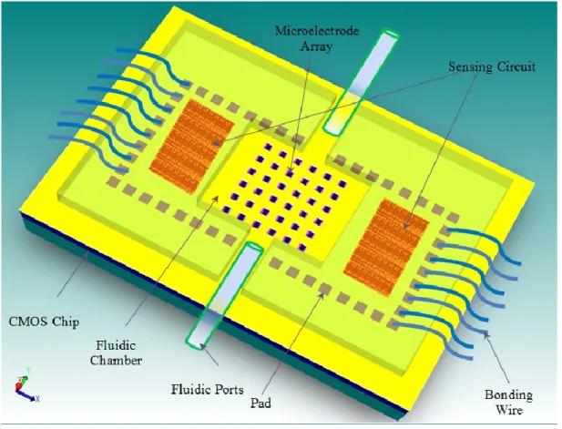
Fig 3.1: Schematic of the Lab-on-Chip system based on a CMOS technology………..…...31
Fig 3.2: Crosssection view of a standard 0.18 µm CMOS process ……….…...32
Fig 3.3: 3D schematic view of the microelectrode array ……….….…33
Fig 3.4: (a)3D structure of the microchannel (crosssection view in upper left and bottom view inupper right) and (b) the function of the through substrate microchannel………..………....34
Fig 3.6: The equivalent circuit to model the injection of a DC current into a microelectrode
pair………...37
Fig 3.7: Conceptual diagram of the sensing mechanism………38
Fig 3.8: Schematic view of the MTB assisted Lab-on-Chip microsystem ………40
Fig 3.9: Packaging scheme ……….…..42
Fig.4.1: Equivalent circuit of a bacterium in between a pair of microelectrodes. (Cdl: double layer capacitor, Rb: resistance of bacterium, Rw: resistance of medium, Cb, capacitance of bacterium) ……….... 45
Fig 4.2: FEM simulation image of the microchannel with face to face electrodes and a 12 µm polymer bead situated in the center of the sensing region. Applied potential is 0.5V at a frequency of 1MHz………....….48
Fig4.3: FEM simulation image of the microchannel with planar electrodes and an 12µm polymer microbead situated in the center of the sensing region. Applied potential is 0.5V at a frequency of 1MHz. ………..….……….49
Fig 4.4: Graph of the relative impedance change at 1MHz for microbeads of various diameters using microelectrodes in face to face and planar orientation. ………..….50
Fig 4.5: Graph of the relative impedance change at 1 MHz for a 4 µm microbead with numerous different channel depths. Electrodes are in face to face orientation.………....51
Fig 4.6: Graph of the relative impedance change for an 8 µm bead at numerous different vertical positions within the sensing region. Microelectrodes are in face to face orientation and results are at a frequency of 1 MHz. ………..…53
Fig 4.7: Graph of the relative impedance change for an 8 µm bead in numerous different horizontal positions within the sensing region. Electrode orientation is face to face and results are for a frequency of 1 MHz ……….……….. 53
Fig 4.8: Graph of the relative impedance change at 1 MHz for a microbead (2 µm in diameter) in the center of the microchannel between a pair of microelectrodes with various size in face to face orientation. ………..54
Fig 4.9: Equivalent circuit model of the MTB bio-carrier system pushing an attached pathogenic bacterium in between a pair of face to face microelectrodes. Rm, Rc ,Rp, Rb, and Rw represent the
resistance of the bacteria membranes, cytoplasm, the anitbody, the microbead, and the medium, respectively. Cm and Cw represent the capacitance of the bacteria membranes and the medium
between the electrodes, respectively..……….………...……56
Fig 4.10: (a) The thin shell structure of a bacterium’ membrane surrounding its cytoplasm in an external medium. (b) The equivalent shell model of the bacteria after applying equation (6). ………...57
Fig 4.11: FEM image of the MTB bio-carrier system with an E. coli bacterium attached in between face to face electrodes. The MTB is located on the left, the anti-body coated microbead in the middle, and the E. coli bacterium on the right. The applied potential is 0.5 V at a frequency of 1 MHz……….………...…58
Fig 4.12: Graph of the relative impedance change over a frequency from 100 Hz to 100 MHz for the 3 cases of the MTB bio-carrier system. microelectrodes are in face to face orientation. A large increase in impedance is seen when the E. coli bacterium becomes attached to the bio-carrier. ………...….59
Fig 4.13: Schematics of the microchip system using the MicraGEM process …….………...61
Fig 4.14: Microscopic image of fabricated microelectrodes, microchannel and a microcoil...62
Fig 4.15: CMOS stimulus generation and detection circuit………...…64
Fig 4.16: Width of pulse for various Rsol values………..…...65
Fig 4.17: Simulation results of delay time according to the impedance variations between the microelectrodes ………...66
Fig 4.18: (a) Layout of the microelectrode and sensing circuit, (b) the size of each pair of microelectrodes on the chip. ………...….68
Fig 5.1: Illustration of anisotropic etchant on silicon substrate ………...72
Fig 5.2: SEM micrograph of a fabricated CMOS chip (a) and a close up view of one pair of microelectrodes (b) ……….…… ...74
Fig 5.3: Side view of the fabricated CMOS die and its thickness measured using a SEM….…..75 Fig 5.4: Microelectrode without passivation layer ……….……..…76 Fig 5.5: Illustration of the FEI FIB system used in this research. The system includes two guns, shown in (a). Ion gun for FIB and electron gun for SEM. Relative position of two guns is
illustrated in (b) ………....77 Fig 5.6: The charging effect on the SEM images and FIB milling process (a) Charging effect observed on an SEM image, (b) FIB beam shift during the milling procedure due to charging effect. ………....80 Fig 5.7: SEM images of improved FIB milling results when applying a charge neutralization procedure ……….…..81 Fig 5.8: FIB re-deposition effect when drilling deep into the sample ……….…..82 Fig 5.9: The re-deposition effects are almost eliminated after applying the GIS when the drilling depth is less than 100 µm. Electrodes are released without artefacts. Drilling depth is 20um (left) and 12um (right) on the SEM Micrographs ………..…....84 Fig 5.10: SEM images of FIB milling results (a) top view of the drilling area on a CMOS die using same TSMC 0.18um fabrication technology; (b, c, d) cross section view of the drilling result, V shape trench can be observed; (e, f) close up view of the re-deposited artefacts at the edge of the trench. …...………..86 Fig 5.11: SEM micrographs showing the thickness of the CMOS die mounted on a silicon wafer used as a sample holder after a RIE thinning process. ………...87 Fig5.12: SEM micrographs of through substrate microchannels and microelectrodes after the FIB milling process. (a) A microelectrode is partially damaged during the 3 hours 19 minutes FIB milling process. The size of the microelectrode is 16µm x 8µm x 2µm (Length x Height x Thickness). The cross-section of the microchannel in between two microelectrodes w is a 16µm square. (b) SEM image from the backside of the CMOS die showing the through substrate microchannel. (c) SEM image of the microchannel after polishing from the backside with FIB. (d) Even with the low dose, FIB milling from the backside, the induced re-deposition covers the
surface of the microelectrodes. (e) Top view (e) and bottom view (f) of a through substrate microchannel with a cross-section area of 10µm by 10µm. This required more than 4 hours milling procedure and one of the microelectrodes was damaged due to the ion beam shift. ………...88 Fig5.13: SEM micrograph of silicon dioxide etching with DRIE without any additional protection layer. (a) Original CMOS die from fabrication foundry (b) After silicon dioxide was etched by AOE, a pair of microelectrodes is released. (c) Notice that the outer side of the microelectrode is also partly etched off. (d) A close-up view of the released microelectrode shows that the top metal layer is partially damaged………...91 Fig 5.14: Profile of the released microelectrode pair and microchannel in between …………....92 Fig 5.15: (a) Dry film structure, (b) roll of dry film, and (c) dry film lamination procedure…….94 Fig 5.16: Microscopy image of a CMOS die covered with a dry film photoresist, after a
photolithography process, opened windows between microelectrodes can be observed in the image………...95 Fig 5.17: The packaged Lab-on-Chip system ………...98 Fig 6.1: (a) Optical microscopy image of the fabricated micro-device used to detect microbeads. The image shows the microchannel and inlets where the solution was introduced, the
microchannel where, through capillary action, the solution travelled, and (b) the microelectrode arrays used to perform the impedance measurements. ………102 Fig6.2: Optical microscope image of an 8 µm microbead passing in between the planar
microelectrodes in the detection channel of the microfluidic device. ………...………104 Fig6.3: Graph showing the experimental impedance pulse recorded for two 8 µm beads passing simultaneously through the detection region. ………..104 Fig 6.4: Experimental setup…..………..……..107 Fig 6.5: Layout of the CMOS Lab-on-Chip system. The microelectrode array is located in the center of the chip. Four reconfigurable sensing circuit modules, working independently, are implemented on both sides. ………...109
Fig 6.6: Pulses obtained with an oscilloscope for various microelectrode pairs that can be reached individually through dedicated selection pins……….……….110 Fig 6.7: Debris left on the surface of the microelectrodes and entrance of the microchannel after the initial test ………...…113 Fig 6.8: SEM micrograph of released microelectrode pairs and microcavities ………...114 Fig.6.9: Varied depth of the medium in the microcavity between a pair of microelectrodes…..117 Fig 6.10: Transmission electronic microscope (TEM) images of the MC-1 bacterium and
magnetosome ………...118 Fig.6.11: Swimming speed measured from a sample of 180 MC-1 bacteria in unbounded sea water conditions ………..……….…119 Fig 6.12: Average swimming speed of the MC-1 MTB as a function of the diameter of the
attached microbead, estimated based on Stoke’s law. ……….120 Fig 6.13: Theoretical wall effect on the swimming speed of the MC-1 bacteria in microchannels with various diameters ………....121 Fig6.14: (a) Microchannel with various widths, from 4 to 12 µm(b) Observed average swimming speed of 50 MC1 bacteria in each microchannel ………….…………...122 Fig 6.15: The swimming speed of MC-1 bacteria as a function of solution viscosity………….123 Fig 6.16: Control of MC-1 bacteria in microchannels. (a) With the magnetic field set to -45o with respect to the parallel channel (far left image), the bacteria begin to swim into the central
microchannel (width of 100 μm) from the upper corner. (b) The magnetic field is then switched to -135o and immediately the bacteria in the central channel begin to migrate into the lower channel (width of 50 μm). (c) The bacteria swim from the bottom of the microchannel to upside and stay after the magnetic field is set at 90o. (d) The bacteria reverse their swimming direction after the magnetic field is set to 45 o (second image from right) and swim back to the central channel (far right image)………..124 Fig 6.17: TEM images of a single MC-1 bacterium attached to a 5 µm microsphere through the antibodies ………....126
Fig 6.18: Displacement of a 2µm bead being pushed by a single MC-1 cell under control of a directional magnetic field. The antibodies were used as the attachment mechanism, and
LIST OF ABBREVIATIONS
AC Alternating current
ADC Analog to digital converter AOE Advanced oxide etch ASE Advanced silicon etch CFU Colony forming unit
CMOS Complementary-symmetry metal–oxide–semiconductor DAC Digital to analog converter
DC Direct current DEP Dielectrophoresis DFP Dry film photoresist DNA Deoxyribonucleic acid DPX Diparaxylylene
DRIE Deep reactive ion etching EDP Ethylene diamine pyrochatechol
EIS Electrochemical impedance spectroscopy ELISA Enzyme-linked immunosorbent assay FEM Finite element model
FIB Focused ion beam
GIS Gas injection system
FRA Frequency response analyzer IMS Immunomagnetic separation ISFET Ion selective field effect transistors
LIF Laser induced fluorescence MTB Magnetotactic bacteria MP Magetophoresis
NMOS N-type metal-oxide-semiconductor PCB Printed circuit board
PCR Polymerase chain reaction PDMS Polydimethylsiloxane
PMOS P-type metal-oxide-semiconductor PMT Photomultiplier tube
RBC Red blood cell RIE Reactive-ion etching SAW Surface acoustic wave
SEM Scanning electron microscope SPR Surface plasmon resonance
TEM Transmission electron microscopy TMAH Tetramethylammonium hydroxide
TSMC Taiwan semiconductor manufacturing company TSV Through silicon via
LIST OF APPENDIX
APPENDIX 1: Focused Ion Beam ……… 159 APPENDIX 2: DRIE Bosch and Cryogenic Technology……….…..162
CHAPTER 1 INTRODUCTION
1.1 Background and motivation
Rapid and on-site bacteria detection and identification, especially for pathogenic bacteria, are becoming a global issue. Diseases caused by pathogenic bacteria are a major cause of human death, accounting for nearly 40% of the total 50 million annual estimated deaths worldwide. Only in the United States, each year, around 76 million people suffer from food-borne illnesses caused by pathogenic bacteria such as Salmonella typhimurium, Escherichia Coli, Staphylococcus aureus, and Campylobacter jejuni [1]. For salmonella only, which is a very dangerous food borne pathogen, approximately 5 million analytical tests are performed annually with the cost of $1billion [2]. E.Coli O157:H7 is a rare strain of E.Coli that is considered to be one of the most dangerous food borne pathogens. It causes 20 000 illnesses and 500 deaths per year in USA [3]. Moreover, pathogenic bacteria are generally present at very low concentrations. For example, the infectious dosage of E.Coli O157:H7 or Salmonella is as low as 10 cells,and the existing standard for maximum concentration E.Coli in drinking water is 4 cells/100 ml. Thus, rapidly identifying low concentrations of pathogenic bacteria down to single bacterium is critical to control and prevent such diseases.
Some conventional bacteria identification methods can detect a single bacterium. For example, a well known technique is based on amplification of the number of bacteria. It generally includes four steps [4,5]: 1) pre-enrichment or pre-amplification: to allow growth and reproduction of all the micro-organisms; 2) selective enrichment: to grow the targeted micro-organisms population to a detectable level; 3) isolation; and 4) confirmation: serological and biochemical analysis to confirm the presence of the targeted pathogenic bacteria. Typically, the whole procedure may require from at least 16 hours to several days. In these cases, by the time the pathogen or undesired microorganisms are identified, the contaminated food, water or other products would probably have been fabricated or shipped to customers. Furthermore, detection of a few pathogens in a clinical sample, food, water, or cosmetics requires a lot of work from highly skilled professional laboratory personnel.
During the last decade, considerable efforts were dedicated to design more automated, faster, and more sensitive detection approaches. Currently, the most sensitive technology is DNA analysis which uses the polymerase chain reaction (PCR) to amplify small quantities of genetic material to determine the presence of bacteria. Optical biosensors, especially the bioluminescence sensors, show extremely high specificity, and can distinguish viable from non viable bacteria. Blasco et al.[6] reported a method to detect Salmonella Newport and E.Coli by measuring the ATP bioluminescence. The sensitivity can reach 104cells/ml. Both technologies usually take hours to produce results.
One common automated bacterial detection technology is based on the changes of electrical characteristics of a medium where the bacteria are cultivated. Electrodes are generally immersed in an aqueous media and connected with an AC or DC power source. The presence of the bacteria is indicated when the measured impedance changes beyond a certain threshold.
However, for all the work reported in literature dealing with impedance detection methods, the detection time depends on the diffusion rate of the target bacteria or the ionic metabolite that the bacteria release in the media (usually, it takes several hours to 7 days). Also, generally, most of the bacteria are not motile. Furthermore, the diffusion rate of the bacteria and their metabolite are very slow, especially under the condition of low-Reynold number laminar fluidics [7, 8, 9]. If the target sample only contains a few bacteria, it takes a long amplifying time for bacteria to reach the detectable level or reach the detection area. Moreover, this method does not guarantee sensitivity and specificity. Some technologies were developed to reduce the time to target bio-entities approaching the electrode array.
Magnetophoresis (MP), optical fields, flow-driven methods, and dielectrophoresis (DEP) have been demonstrated as effective techniques [10-20] to manipulate or transport bio-entities. The flow-driven approach utilizes hydrodynamic forces to manipulate bacteria and particles. However, the laminar stream required to induce the displacement of bacteria and particles needs to be accurately controlled. This requires the fabrication of complex microchannel networks [18]. Optical methods depend on accurate beam focusing and alignment between the targeted particles and require complicated optical instruments [19]. DEP and MP are the most widely adopted particle and cell transportation techniques. DEP based transportation is achieved by the use of an
inhomogeneous electric field [10, 11, 13], while MP uses a magnetic field gradient to cause particle migration [20]. Both methods encounter limitations in their applications. First, in order to generate large enough electric/magnetic field gradients, electrodes or magnets have to be patterned in channels or chambers where the particles are carried. The generated force is relatively strong in the vicinity of the electrodes, but decreases with the distance from the electrode's plane. In order to maintain enough force on particles or bacteria to combat the hydrodynamic drag force, a high density of electrodes near the desired transportation paths is required, which limits the effective transportation distance. Moreover, in order to realize two or three dimensional transportation of particles, fairly complicated implementations of electrodes/magnets is needed [16, 12]. Second, in order to move the desired particles and bacteria, relatively high frequencies and voltage amplitudes are required to induce a sufficient DEP force, which may break down the bacteria’s membrane and affect the viability of target bacteria. Additionally, for the transportation of bio-entities, the high voltage on the electrodes or electro-magnets induces joule heating, which may also cause damage on cells [17]. Third, DEP and MP both depend on the properties of the entities being manipulated and the medium containing them. Thus, unwanted entities with similar dielectric or magnetic properties to the targeted entities can be selected and controlled, which causes significant difficulties when trying to achieve high selectivity.
Through this brief introduction of conventional and current approaches, we conclude that there are at least four major challenges for rapid, specific, low-volume bacteria detection. 1. An extremely sensitive detection method is needed to identify single bacterium. 2. An efficient way to bring the targeted bacteria to the sensing area is needed. 3. The biosensor should be low cost, field deployable, and functioning in an automatic manner. 4. Those specifications should be achieved without sacrificing the viability of the target samples. In this research, we are trying to address the first three challenges by combining the conventional microelectronic technology with recent advances in microfluidic/lab-on-chip technology. The specificity of the single bacterium detection assisted by magnetotactic bacteria is also evaluated.
1.2 Overview of the thesis
The objective of the thesis is to contribute to the development of a microfluidic/CMOS hybrid system aimed at rapid single bacterium detection. The single bacterium detection is realized by impedance measurement through an array of vertical, face to face microelectrodes which is implemented onto a CMOS chip by stacking the metal and via layers together. Each microchannel created using post-processing procedures, goes through a CMOS die, forcing bacterium to pass between a pair of microelectrodes constructed using layers of a conventional CMOS process. With medium flow, bacteria are allowed to pass through the microchannels, where impedance variations are measured using a microelectrode pair on the wall, which is connected to on-chip sensing circuits. The through substrate microchannels allow high throughput and real-time detection for single bacterium to be achieved in a continuous manner. Two CMOS post-processing procedures, including Focused Ion Beam (FIB) for rapid prototyping and Deep Reactive Ion Etching (DRIE) for batch fabrication, are evaluated. A specific packaging method for encapsulating the whole system is also presented. The fabrication and testing results confirm that a high density of vertical microelectrodes can be constructed on a CMOS chip with a relatively simple post-processing procedure. The embedded sensing circuit can greatly improve the detection sensitivity. Preliminary tests show that a 2% electrical impedance change due to conductivity variations between a pair of microelectrodes can be distinguished by the proposed system. In this thesis, the feasibility of using MC-1 magnetotactic bacteria as a bio-carrier to accelerate the screening speed and achieve specificity is also explored.
1.3 Contribution of this research
1) Proposed and implemented face to face microelectrode arrays using CMOS technology. In this research, we first proposed a face to face microelectrode constructed by stacking metal layers using a CMOS technology. The idea was initially published in 2007 as :
Z. Lu, R. Denomme, and S. Martel,“Micro/Nanoparticle Detection: An impedimetric microsensor based on CMOS technology”, 7th IEEE International Conference on Nanotechnology (IEEE-NANO), Hong Kong, China, Aug. 2-5, 2007
R. Denomme, Z Lu., and S. Martel, “An integrated biosensor for the detection of bio-entities using magnetotactic bacteria and CMOS technology”, 29th Annual International Conference of the IEEE Engineering in Medicine and Biology Society (EMBS), Lyon, France, Aug. 23-26, 2007.
The latest results are presented in the paper submitted to Journal Biomicrofluidics with the title of “A novel vertical microelectrode array based on CMOS technology, design, microfabrication, and test”.
2) This research explored the feasibility of using focused ion beam (FIB) technology and conventional deep reactive ion etching (DRIE) to achieve through substrate microchannels(Vias) generally called TSV in 3D IC technology. Part of the results was published on IEEE Mixed-Signal Test Workshop (IMS3TW) 2008 with the title: “A hybrid bacteria and microparticle detection platform on a CMOS chip: design, simulation and testing considerations”.
3) This research also proposed a novel impedimetric biosensor based on CMOS technology for single bacterium detection and analysis. The proposed sensing mechanism and circuit are novel, very sensitive, and impose no need for complex signal processing circuitry. The idea and results were published at IMS3TW 2008 with the title: “A hybrid bacteria and microparticle detection platform on a CMOS chip: design, simulation and testing considerations”.
4) This research also explored the feasibility of using magnetotactic bacteria as a bio-carrier in the proposed system to enhance the detection specificity. The idea, prototype, and some experimental results were published in several papers.
Z. Lu, J. El-Fouladi, Y. Savaria, and S. Martel, “A hybrid bacteria and microparticle detection platform on a CMOS chip,” The 11th International Conference on Miniaturized
Systems for Chemistry and Life Sciences (µTAS), Paris, France, Oct. 7-11, 2007.
R. Denomme, Z. Lu, and S. Martel, “A microsensor for the detection of a single pathogenic bacterium using magnetotactic bacteria-based bio-carriers: simulations and preliminary experiments”, 29th Annual International Conference of the IEEE Engineering in Medicine
J. El Fouladi, Z. Lu, Y. Savaria, and S. Martel, “An integrated biosensor for the detection of bio-entities using magnetotactic bacteria and CMOS technology”, 29th Annual International
Conference of the IEEE Engineering in Medicine and Biology Society (EMBS), Lyon, France, Aug. 23-26, 2007.
Z. Lu. and S. Martel., “Controlled bio-carriers based on magnetotactic bacteria”, The 14th International Conference on Solid-state Sensors, Actuators, and Microsystems (Transducers 2007), Lyon, France, June 10-14, 2007.
Z. Lu, O. D. Truong, W. André. and S. Martel, “Preliminary design of a biosensor based on MC-1 magnetotactic bacteria,” The 9th World Congress on Biosensors (Biosensors 2006), Toronto, Canada, May 10-12, 2006.
Z. Lu. and S. Martel, “Preliminary investigation of bio-carriers using magnetotactic bacteria,” Proceedings of the 28th IEEE-EMBS Annual International Conference of the
Engineering in Medicine and Biology Society, pp. 3415-3418, New York, Aug. 30 – Sept. 3, 2006.
Z. Lu and S. Martel, “Microfluidic system for assessing the controllability of MC-1 magnetotactic bacteria as carriers in micro-channels,” The Nanotechnology Conference and Trade Show (NSTI) Nanotech, Boston, MA, USA, May 7-11, 2006.
1.4 Structure of the thesis
This thesis describes the systematic development of a microfluidic/microelectronic system based on CMOS technology and CMOS post-processing, covering topics such as bacteria detection, microfabrication, and microsystem integration. It is divided into seven chapters. The topic of each chapter is described as follows.
Chapter 1 presents the background, motivation, objective, and major contributions of the research.
Chapter 2 reviews the literature and development of technologies used in this research, including the single bacterium sensing technology, impedemetric biosensor, CMOS-based lab-on-chip system and CMOS post processing fabrication technology. The strengths and weaknesses of conventional technologies are
presented. The advantages and challenges of CMOS based biosensor are discussed as well.
Chapter3 defines the system architecture including a novel microelectrode structure based on a standard CMOS technology, sensing mechanism, on-chip microelectronic sensing circuit, system packaging methods. Design considerations such as biocompatibility, robustness and reliability are also discussed in this chapter, and finally, the feasibility of utilizing magnetotactic bacteria as bio-carriers to achieve specificity and high screening speed is also presented.
Chapter 4 focuses on optimizing dimensions of microelectrodes and microchannels using finite element modeling (FEM) simulations. The detailed circuit simulations provide design specifications for sensing circuits. Finally, the layouts of a prototype device based on the MicraGEM technology and a lab-on-chip based on a standard CMOS process are given.
Chapter 5 mainly focuses on some CMOS post-processing procedure for releasing the microelectrode array and forming through substrate microchannels. Two microfabrication technologies, FIB and DRIE, are discussed and compared, illustrated with microfabrication results. The MicraGEM technology used to fabricate prototype chips is also presented. The system packaging steps are finally described.
Chapter 6 presents the experimental results obtained with the proposed system. The test results are discussed and interpreted. The system deficiencies and possible remedies are presented. Preliminary experimental results related to utilizing the MC-1 magnetotactic bacteria to obtain bacterium specific detection are also presented.
Chapter 7 summarizes the thesis and points towards future directions to optimize the proposed systems.
CHAPTER 2 LITERATURE REVIEW
2.1 Introduction
As briefly introduced in Chapter 1, rapid and effective detection of single pathogenic bacterium is extremely important in diagnosis, disease control and prevention, biomedical and recent fight against bioterrorism. As an example, around 81 million persons in the USA are affected by food-borne diseases each year, with a cost of $8 to $10 billion per year [21-24]. Recently, outbreaks of food and air-borne pandemic diseases caused by E-coli:O157, Salmonella, and H1N1 indicated that, with the change of human living style and highly centralized and integrated food processing, an ultrasensitive and rapid biosensor is urgently required both for early accurate diagnosis and disease prevention. This chapter aims to give an overview of pathogen bacteria detection methods. Since the literature of bacteria detection is vast, we will focus on three main topics: a) conventional methods for pathogenic bacteria detection, b) impedimetric detection methods and c) micro-nanotechnology and microelectronic technology based detection methods. The generic advantages and limitations for each method are also given. Based on the research literature, breakthroughs such as adoptions of magnetic beads, nanoparticles and integrated microelectronic-microfluidic hybrid microsystem will be highlighted.
2.2 Conventional individual bacteria detection methods
Polymerase chain reaction (PCR), culture and colony counting methods, as well as immunology-based methods are the most widely used methods for pathogen detection. They involve DNA sample amplification and analysis, bacteria culturing, amplification and identification, and antigen–antibody interactions, in sequence. In spite of weaknesses such as the long turnover time for the analysis, the complexity of the procedure and requirement for highly skilled staff, they still represent the most reliable and accurate detection methods among available technologies. These methods are often combined together to yield more robust results. The strengths and weaknesses of each technology are discussed below.
2.2.1 Plating, culturing, and counting method
The plating, culturing, and counting method was developed 100 years ago. As a standard procedure, it is still widely adopted in clinical laboratories all over the world [25]. Fig. 2.1 illustrates a typical protocol for identifying pathogenic bacteria from samples. Generally, the process starts with pre-enrichment, in which samples are incubated in a nutritious medium to allow amplification of the targeted bacteria [26~28]. Pre-enriched samples are then transferred into a specially formulated medium for selective enrichment, where the targeted bacteria are allowed to grow, while the growth of other bacteria is suppressed. After that, culture-enriched samples are plated onto selective and differential media, normally in a Petri dish, where different bacterial types are presumptively recognized on the basis of distinguishing colony characteristics. Finally, the results need to be verified by biochemical identification or serotyping procedure. Typical processing times range from 4 to 9 days for initial identification and 14 to 16 days for verification [29].
Fig 2.1: Flow chart showing the procedure for the isolation and identification of pathogenic bacteria from samples (Adapted from [25]).
As a result, this conventional method is inadequate for making real-time detection and identification. The situation gets even worst if the initial concentration of the pathogenic bacteria is very low, for example, the infectious dose of E. coli O157:H7 is around 10–100 cells, and the presence of even a single bacterium in food may pose a serious health risk [30, 31].
2.2.2 Polymerase chain reaction (PCR)
PCR is a nucleic acid amplification technology, which was developed in the mid 80s [32] and is very widely used in pathogenic bacteria detection. Firstly, DNA is extracted and purified from a sample, such as saliva, blood or water. Then, the DNA samples go through several thermal cycling illustrated in Fig 2.2, consisting of cycles of repeated heating and cooling, including denaturing, annealing, extension and polymerization procedure, to cause DNA melting and enzymatic replication of the DNA. Primers (short DNA fragments) containing sequences complementary to the target region along with a DNA polymerase are key components to enable selective and repeated amplification. As PCR progresses, the DNA replicates itself in the fashion of a chain reaction in which the DNA template is exponentially amplified. Within hours, a single or a few copies of a piece of targeted DNA generate thousands to millions of copies of a particular DNA sequence [33, 34]. The presence of the amplified sequence is subsequently detected by gel electrophoresis [35].
Fig2.2: Schematic of one PCR cycle taking place in a thermocycle [32].
There are various PCR methods developed for bacterial detection: for example, a) real-time PCR [36], b) multiplex PCR [37], and c) reverse transcriptase PCR (RT-PCR) [38]. There are also methods that couple PCR to other techniques such as, for example, surface acoustic wave (SAW)
sensor [39]or evanescent wave biosensors [40]. PCR is a lot less time-consuming than the culturing and plating method introduced above. Without considering the sample preparation and pre-enrichment steps, generally, it takes from 5 to 24 hours to reach the detectable threshold with PCR.
It is worth mentioning that the multiplex PCR method is very useful as it allows the simultaneous detection of several organisms by introducing different primers to amplify DNA regions coding for specific genes of each bacterial strain targeted [41].
The main advantage of real-time PCR is that the results can be achieved quickly without too much manipulation. This technique bases its detection in the fluorescent emission by a specific dye when it bonds itself to the targeted amplification. Since the fluorescence intensity is proportional to the amount of amplified product [42], it is possible to follow the amplification in real time, thus eliminating laborious post-amplification processing steps such as gel electrophoresis. Different alternative probes, deriving from this principle, have been developed recently [43].
One of the major limitations of PCR techniques is that the user cannot discriminate between viable and non-viable bacteria because DNA is always present independent of the viability of the bacterium.
2.3 Optical methods of single bacterium detection
Optical detection methods are probably the most popular tools in bioanalysis and have received considerable interest for rapid detection of contaminants [44, 45], toxins or drugs [46], and bacterial pathogens due to their sensitivity and selectivity. Optical-based detection offers large number of subclasses based on absorption, reflection, refraction, dispersion, infrared, Raman spectroscopy, chemiluminescence, fluorescence, and phosphorescence. However, all the above subclasses require a suitable spectrometer to record the spectrochemical properties of the analyte. The surface fluorescence and Surface Plasmon Resonance (SPR) are the most sensitive optical detection technology.
2.3.1 Fluorescence detection
Fluorescence occurs when a valence electron is excited from its ground state to an excited singlet state. The excitation produced by the absorption of light of sufficient energy usually through a laser source is called laser induced fluorescence (LIF). When the electron returns to its original ground state it emits a photon at lower energy, leading to light emission with a longer wavelength than the absorbed light since some of the energy is lost due to vibrations. The light emission takes place shortly after absorption, usually within 10ns. One of the typical applications of this phenomenon is the flow cytometry[47].
Flow cytometry is a widely adopted method for high throughput analysis of suspended particles, bacteria and other microorganisms. A typical flow cytometer with sorting function works as illustrated in Fig2.3. First, the sample flow containing microparticles is focused by a hydrodynamic flow focusing method by using the surrounding sheath flows. Then, the sample flow passes through an optical detection region formed by the intersection of the flow with laser beams, and detectors use the scattered light from the cell or bacteria samples to analyze the types and sizes of the cells/bacteria. The fluorescence labelling method can also be used to collect induced fluorescent signals from the fluorescence-labelled cells/bacteria. The fluorescence emitted from the cells/bacteria through several optical components is then collected by a digital camera or photomultiplier tubes (PMTs) and then recorded by a computer for image or signal processing. Finally, pairs of electrodes are used to sort different cell samples [48].
Fig 2.3: Schematic view of the operation principle of a flow cytometer for cell counting and sorting [49].
Not only can flow cytometer be used for single bacterium detection and identification, it has also been demonstrated for measurement and analysis of various cell properties, including surface antigen, intracellular antigen, transgenic expression, and immunoassay. However, delicate and complex optical components including focused laser beams, various optical detecting/filtering devices and complicated control circuits make the system relatively expensive. The calibration process is also relatively complicated, which usually requires an experienced, skilled staff to operate.
2.3.2 Surface plasmon resonance (SPR)
SPR biosensors [50] measure changes in refractive index caused by structural alterations on the surface of a thin film metal (typically Gold or Silver). In SPR biosensors, a surface plasmon is excited on a thin metal film to the surface of which a bio-recognition element is attached, for example, antibody or biotin. The binding of a bacterium or other bio-entities in solution to the bio-recognition element on the SPR sensor surface produces a local increase in the refractive index. The refractive index change gives rise to a change in the propagation constant of the
surface plasmon, which is subsequently measured as a change in the coupling angle of incidence (SPR sensors with angular modulation) or in the coupling wavelength (SPR sensors with wavelength modulation). A schematic view of the working principle of a SPR is illustrated as Fig 2.4.
Fig 2.4: Schematic view of the working principle of SPR (a) prism-coupled configuration and (b) resonance shift in the reflected light spectrum [51]
SPR is a label free, highly selective, and fast (when the bacterium is bound on the surface of the SPR sensor) detection technology. Another major advantage of using SPR technology is that SPR sensors can detect bacteria, particles, and analytes in complex samples (e.g., blood, urine, stool extract, fruit juices, and food extracts) with limited or no sample preparation, purification or pre-amplification, SPR has successfully been applied to the detection of pathogen bacteria by means of immunoreactions[52,53]. The main disadvantages of this powerful technique lay in its complexity, demand for specialised staff, expensive equipment and relatively large size of desktop or bench top instruments implementing it. Since most of the microorganisms, e.g. bacteria are not mobile, diffusion is the only way for bacteria to migrate to the sensor surface. The total detection time with a SPR sensor is typically dominated by the ability of the target bacterium to reach the surface and bind to an immobilized antibody or biotin. As diffusion tends to be an extremely slow process, it limits the sensor response time significantly.
2.3.3 Immunology-based methods
The field of immunology-based methods for bacteria detection provides very powerful analytical tools for a wide range of targets. The enzyme-linked immunosorbent assay (ELISA) [54] test is the most established technique nowadays as well as the source of inspiration for many biosensor applications. ELISAs combine the specificity of antibodies and the sensitivity of simple enzyme assays by using antibodies or antigens coupled to an easily assayed enzyme. Fig. 2.5 illustrates the principle of a typical “sandwich ELISA”[55], which is the most common kind.
Fig 2.5: Schematic view of the sandwich-ELISA protocol [54].
Another important application of the immunology-based is immunomagnetic separation (IMS) [56], which extracts and captures targeted pathogens from a medium by introducing functionalized magnetic microbeads usually coated with specific antibody[57~60]. Off-the-shelf functional magnetic microbeads are available from a number of suppliers. Beads of widely
ranging sizes (from several nano-meters up to a few tens of micron meters) are available depending on the application.
Generally, functional magnetic beads are mixed with the medium containing targeted bacteria, after a suitable mixing procedure, targeted bacteria are supposed to attach to the surface of magnetic beads, then the mixed medium flows through a fluidic channel, where electromagnets or permanent magnets are used to capture the magnetic beads on the wall of the channel, thus separating the targeted bacteria from the medium and other bio-entities to realize the purification process. By removing the local external magnetic field, magnetic beads attached with targeted bacteria are released for further investigation. IMS can be combined with almost any other detection method, such as, optical, magnetic force microscopy, magnetoresistance [61] and Hall Effect [62] for further quantification and identification of the bacteria. The working principle is illustrated as Fig 2.6
Fig 2.6: Schematic depiction of a typical magnetic separation procedure [56]
2.4 Electrochemical biosensors
These devices are mainly based on the observation of electric current or potential changes due to interactions occurring at the sensor-sample interface. Techniques are generally classified
according to the observed parameter: current (amperometric), potential (potentiometric), or impedance (impedimetric), but they all use electrodes or electrode array to produce or collect signals from medium containing target analyte, bacterial or other bio-entities. Compared to other methods, illustrated in Table 2.1-2.5 [63] below, electrochemistry allows the analyst to work with turbid samples. The main advantages of this kind of sensor include short response time, ease of integration, high reliability and much lower cost of equipment compared with conventional methods. On the other hand, in general, compared with their counterparts such as optical or culturing and counting methods, electrochemical methods present slightly less selectivity. Fig 2.7 compares the sizes of the various components of an electrochemical biosensor [63]. In this section, the amperometric and potentiometric methods are reviewed briefly. The impedimetric technology is discussed in detail in the next section.
Table 2.1: Detection of E.coli[63]
Detection technique Sample type Time of analysis
Working range
(CFU* mL−1) Detection limit (CFU mL−1)
ELISA Ground beef Next day 103–104 1.2 × 10³ PCR-ELISA Milk 5 h 100–104 100 PCR-electrophoresis 2 h 101–104 1000 Real-time PCR Culture medium
Ground beef 5 h 20 min 3 h 20 min 5–5 × 10⁴cells 5 cells 1.3 × 10⁴ cells/g RT-PCR coupled to
fluorescence Drinking water 30 min 1–106 102 Fiber optic immunosensor Culture 10 h Tested up to 6.5 × 10⁴ 2.9 × 10³ SPR biosensor Culture NA 102–109 102 QCM Immunosensor Culture/water 170 min 103–108 103 Amperometry Culture 30 min 100–600
Conductimetric
biosensor Mixed culture containing up to five different microorganisms Water
10 min 10–105 79
Vegetable wash water 6 min 10–106 81 Impedimetric
immunosensors
Culture/water 10 min 104–107 104 in culture and 107 in water.
Table 2.2: Detection of Legionella pneumophila[63]
Detection technique Sample type Time of analysis
Working range (CFU/ mL)
Detection limit (CFU/ mL) Colony count Water 5–14 days 2.5–994 1
PCR 1–2 h 0.015–150 1–10
Sandwich hybridization
assay (SHA) Water 1–2 h 1.8 × 10³ cells SPR Culture 2 h 20 min 102–109 102
Table 2.3: Detection of Campylobacter jejuni[63]
Detection
technique Sample type
Time of analysis Working range (CFU/mL) Detection limit (CFU/mL) ELISA Bovine vaginal mucus and
prenuptial washing 5 days 105–107 105–106 Real-time
PCR-IMS Chicken fecal suspension 4 h 100–150 Total internal
reflection Culture Over 2 h
ca. 103 Amperometric
biosensor
Culture and chicken carcass,
wash water 2–3 h
103–107 2.1 × 10⁴
Table 2.4: Detection of Salmonellae[63]
Detection technique Sample type Time of analysis
Working range (CFU mL−1)
Detection limit (CFU mL−1) IMS-plating Raw chicken Next day 1–10
IMS-ELISA Next day 106–109 106
Electrochemical sandwich
ELISA Meat Same day Unknown 1–10 cells/25 g
PCR-ELISA Milk Next day 1–108 103
QCM Phosphate buffer 60 min 105–5 × 10⁸ 104 Amperometric biosensor Culture and water 1–2 h Not specified 5 × 10⁴
Table 2.5: Detection of Listeria monocitogenes[63]
Detection technique Sample type Time of analysis
Working range (CFU /mL)
Detection limit(CFU/mL)
PCR Beef simple Next day 1000 cfu/g
Real-time PCR Fresh product (salad) Same day 100–1000 1000 Magnetic DNA
isolation-PCR Milk 7 h 1–105 10
Amperometry Phosphate buffer and
milk 3–4 h 103–106 9 × 10²
Amperometric
immunosensor Culture > 2 h 104–107
Fig2.7: Diagram ofthe comparative sizes of the parts integrating a biosensor [43]
2.4.1 Amperometric methods
This is perhaps the most common electrochemical detection method used in biosensors. Its working mechanism is based on the assumption that the relationship between the concentration of analyte and the measured current from a sensor is linear, compared with a logarithmic relationship in potentiometric systems. This makes amperometric biosensors well suited for bacterial assay. Amperometric biosensors have the advantage of being highly sensitive, rapid, and inexpensive. Generally, the sensor potential is set at a value where the analyte, directly or indirectly, produces a current at the electrode. However, there are some biosensors which cannot allow direct electron exchange between the electrode and either the analyte or the biomolecule. In those cases, redox mediators are required [64](Redox mediators are small size compounds able to reversibly exchange electrons between both the sensor and the enzyme of choice (e.g.,
ferricyanide, osmium or ruthenium complexes, dyes, etc.)). Many different combinations and strategies to build biosensors are possible. The actual choice depends on constraints imposed by sample matrix, analyte, or usability [65]. Bacterial biosensors that do not differ much from more conventional biosensors are found in [66]. In this work, E. coli is detected in 30 min and between 100 and 600 cells/mL using a flow-through immunofiltration method coupled to amperometry. Fig.2.8 shows how this disposable amperometric immunofiltration sensor works.
Fig 2.8 Diagram of how an amperometric immunofiltration biosensor works [63]
2.4.2 Potentiometric methods
The potentiometric sensor has characteristics that are different from amperometric sensors in several aspects: a). The measured species, usually concentration of ions (such as H+, NH4+, etc.) are not consumed. b). The sensor measures the activity (for dilute solutions, molar concentration can be used), of a specific ion in reference to its predefined threshold. c). The ion specificity comes entirely from the membrane. For example, there are all kinds of ion selective membranes,
for example, specific to H+, NH4+, or Ca++, etc. d). The output of a potentiometric sensor is in voltage proportional to the natural log of ion concentration and independent of the sensor size. Since potentiometry yields a logarithmic concentration response, the technique enables the detection of extremely small concentration changes. One of the most successful applications of this approach is called ion selective field effect transistors (ISFETs) [67] which utilize the semiconductor field-effect to detect biological recognition events. ISFETs use an electric field to create regions of excess charge in a semiconductor substrate in order to enhance or decrease local conductivity. They consist of a p-type silicon substrate with two n-doped regions known as source and drain, separated by a short distance (gate) covered by a layer of insulator. The gate insulator is typically SiO2 and it is covered by an ion selective membrane which is selectively
permeable to a certain ion, e.g., K+, Ca2+, F−, as described in [68]. More details on the functioning of ISFETs are reviewed in [69]. The application of these devices in the area of biosensors is constrained due to following issues: a) most bio-molecular immobilization methods are not compatible with the ISEFT fabrication technology b) it offers poor detection limits, linear range, and reproducibility, and c) it has inadequate device stability.
The potentiometric detection may be applicable to a wide range of bacteria. However, similarly toamperometric methods, the response times highly rely upon microorganisms’ growth, thus potentiometric biosensor cannot provide a real-time analysis and pre-enrichment steps are required.
2.5 Electrochemical impedance spectroscopy (EIS)
Impedance spectroscopy is a powerful method used to characterize the chemical and physical properties of solid, liquid, and gas phase conductive materials. In the last two decades, this technique has gained widespread adoption in developing biosensors for monitoring the catalyzed reaction of enzymes; the bio-molecular recognition events of specific proteins, nucleic acids, whole cells, antibodies or antibody-related substances; presence of bacterial cells in the aqueous medium or growth of bacterial cells.
In this technology, generally, a small amplitude sinusoidal excitation signal is applied to a transducer, and resulting current is used to calculate the impedance at each of the frequencies
![Fig 2.1: Flow chart showing the procedure for the isolation and identification of pathogenic bacteria from samples (Adapted from [25])](https://thumb-eu.123doks.com/thumbv2/123doknet/2337738.33185/32.918.300.652.548.816/showing-procedure-isolation-identification-pathogenic-bacteria-samples-adapted.webp)
![Fig 2.3: Schematic view of the operation principle of a flow cytometer for cell counting and sorting [49]](https://thumb-eu.123doks.com/thumbv2/123doknet/2337738.33185/36.918.321.653.123.502/fig-schematic-view-operation-principle-cytometer-counting-sorting.webp)
![Fig 2.4: Schematic view of the working principle of SPR (a) prism-coupled configuration and (b) resonance shift in the reflected light spectrum [51]](https://thumb-eu.123doks.com/thumbv2/123doknet/2337738.33185/37.918.159.745.263.512/schematic-working-principle-coupled-configuration-resonance-reflected-spectrum.webp)
![Fig 2.5: Schematic view of the sandwich-ELISA protocol [54].](https://thumb-eu.123doks.com/thumbv2/123doknet/2337738.33185/38.918.164.752.356.890/fig-schematic-view-sandwich-elisa-protocol.webp)
![Fig 2.6: Schematic depiction of a typical magnetic separation procedure [56] 2.4 Electrochemical biosensors](https://thumb-eu.123doks.com/thumbv2/123doknet/2337738.33185/39.918.148.758.527.884/schematic-depiction-typical-magnetic-separation-procedure-electrochemical-biosensors.webp)
![Table 2.1: Detection of E.coli[63]](https://thumb-eu.123doks.com/thumbv2/123doknet/2337738.33185/40.918.150.772.507.912/table-detection-of-e-coli.webp)
![Table 2.4: Detection of Salmonellae[63]](https://thumb-eu.123doks.com/thumbv2/123doknet/2337738.33185/41.918.149.774.764.984/table-detection-of-salmonellae.webp)
![Table 2.5: Detection of Listeria monocitogenes[63]](https://thumb-eu.123doks.com/thumbv2/123doknet/2337738.33185/42.918.157.764.137.654/table-detection-of-listeria-monocitogenes.webp)