UNIVERSITÉ DE MONTRÉAL
IMPROVEMENT DEBURRING CONSISTENCY OF FUEL NOZZLE PARTS
SEYEDEHSHAGHAYEGH ROUZMEH DÉPARTEMENT DE GÉNIE MÉCANIQUE ÉCOLE POLYTECHNIQUE DE MONTRÉAL
MÉMOIRE PRÉSENTÉ EN VUE DE L’OBTENTION DU DIPLÔME DE MAÎTRISE ÈS SCIENCES APPLIQUÉES
(GÉNIE MÉCANIQUE) MAI 2012
UNIVERSITÉ DE MONTRÉAL
ÉCOLE POLYTECHNIQUE DE MONTRÉAL
Ce mémoire intitulé:
IMPROVEMENT DEBURRING CONSISTENCY OF FUEL NOZZLE PARTS
présenté par :
en vue de l’obtention du diplôme de :
ROUZMEH Seyedehshaghayegh
a été dûment accepté par le jury d’examen constitué de :
Maîtrise ès sciences appliquées
M. LAKIS Aouni A M.
., Ph.D., président BALAZINSKI Marek,
M.
Ph.D., membre et directeur de recherche HOANG Canam
M.
, Eng., membre et codirecteur de recherche ENGIN Serafettin, Ph.D., membre
ACKNOWLEDGMENT
My special thanks are extended to my father for his dedication and support and my mother for the love and strength she gave me.
I would also like to express my profoundest gratitude to my research director, professor Marek Balazinski, for his support and patience and for the kindness in his heart, which makes him more than an advisor to me.
I would also like to offer my sincerest appreciation to my industrial supervisor Mr. Canam Hoang, which his support, expertise and advises helped me conducting this project.
Finally, I wish to acknowledge the support of Pratt and Whitney Canada, for enabled this study to be performed.
RÉSUMÉ
L'objectif de cette étude est d'améliorer la qualité produite par l'ébavurage des pièces de tourbillon d’air. Ces pièces de haute précision sont habituellement ébavurées de façon manuelle par un humain. Comme première étape vers l'amélioration de ces ébavurages, l'analyse des causes fondamentales a été réalisée. Puis les conditions actuelles des pièces ont été étudiées par des expériences utilisant la méthode de Taguchi. L’analyse de la variance a été menée sur les données recueillies pour illustrer la significativité des facteurs des plans d’expériences et de leur contribution. La formation de bavures sur les pièces a été étudiée, trois régions principales ont été analysées. Le modèle cyclique de formation de bavures a été observé à l'état d'équilibre de la formation de bavures. L'amélioration du profil de bavure a été réalisée suivant deux méthodes : 1) le liquide de refroidissement à travers les trous d’huile du foret et 2) en position verticale du perçage. Le procédé d’ébavurage avec des abrasifs magnétiques a été évalué comme une alternative possible pour l'ébavurage manuel. Les échantillons ont été traités sous deux conditions : 1) pas de préparation en sortie de trou après perçage et 2) sortie de trou préparée. Les échantillons dont leurs arrêtes (sorties de trou) ont été préparées, ont montré une amélioration significative en terme de régularité.
ABSTRACT
This study is about improving the deburring consistency of air-swirlers. The parts are high precision critical components of hot section of aircraft engine, which have key role in stabilizing the combustion flames via providing turbulent air-fuel mixture for the combustion chamber. The product needs to meet high standards including edge quality and surface finish. These small in process parts are deburred manually due to their size, complex geometry, restricted access and adjacent critical surfaces to the edges.
The title of the research was selected through investigations, cost estimation and prioritization of deburring issues within Pratt and Whitney Canada.
In order to tackle the issue, a comprehensive study was conducted on state of the parts. The investigation aimed to lay a basis of comparison to evaluate the further improvement approaches. The parts were investigated through experiments, designed based on Taguchi method. For designing the experiments, root cause and fault tree analysis was performed first. Then the preliminary experiments were employed to define the level of affecting parameters. The designed experiments were conducted on four different in process parts. The data was analyzed using STATISTICA software. Based on the results, the areas, which required further investigation, were identified and feasible improvement strategies were proposed.
The complementary experiments comprise two main topics: burr control and alternative deburring process.
In order to improve the burr characteristics of the parts, burr formation study was conducted. The parts were assessed during various manufacturing cycles. Burr formation pattern was identified on the parts. Based on observation it was concluded that the pattern could be attributed to the temporary degradation of tool properties due to elevated temperature cutting during short time intervals. Hence, the temperature of the cutting tool was measured during production via thermal sensors. With respect to validation of hypothesis two main strategies were proposed in order to provide proper and homogenous cooling to reduce the tool temperature during the cut: Coolant thru design drill and vertical position for production. Both approaches revealed significant results. The burr height decreased and burr profile improved using both methods.
The feasible alternative deburring processes were assessed and listed. Among the proposed ones, magnetic abrasive deburring was selected for the test based on probability of success and project budget. The samples were processed in their original condition and with prepared edge. The preparation was performed manually. The operators were asked to remove the burrs without creating break edge. The unprepared samples had burrs and rolled edge after the process while the prepared samples had fine and uniform break edge around the part. The deburring results of prepared samples were remarkably consistent from hole to hole and part to part.
TABLE OF CONTENT
ACKNOWLEDGMENT ... iii
RÉSUMÉ ... iv
ABSTRACT ... v
TABLE OF CONTENT ... vii
LIST OF TABLES: ... x
LIST OF FIGURES ... xi
LIST OF ABBREVIATIONS ... xiv
INTRODUCTION ... 1
CHAPTER 1 PRE-PROJECT PHASE ... 5
1.1 Methodology ... 5
1.1.1 Project Distribution ... 7
1.1.2 Prioritization Criteria ... 7
1.2 Result ... 9
CHAPTER 2 PROBLEM DEFINITION AND APPROACH ... 11
CHAPTER 3 BURRS IN DRILLED HOLES ... 14
3.1.1 Burr phenomenon and characteristics ... 14
3.2 Burr formation in drilling process ... 18
CHAPTER 4 BURR REMOVAL AND DEBURRING PROCESSES ... 22
4.1 Edge requirements ... 22
4.2 Hand deburring ... 23
4.4 Electropolish and Burlytic Deburring ... 27
4.5 Cryogenic Deburring (Via Liquid Nitrogen)... 29
4.6 Thermal Energy Deburring ... 30
4.7 Magnetic Abrasive Deburring ... 31
4.8 Laser Deburring ... 32
CHAPTER 5 METHODOLOGY... 34
5.1 Investigation of current state of the parts ... 34
5.1.1 Planning the experiments ... 35
5.1.2 Implementation ... 49
5.1.3 Analysis ... 50
5.2 Complementary experiments ... 50
5.2.1 Investigation of burr formation during manufacturing ... 51
5.2.2 Evaluation of alternative deburring processes ... 52
5.3 Inconsistency criteria ... 53
CHAPTER 6 ANALYSIS, RESULTS, AND DISCUSSION ... 55
6.1 Preliminary tests ... 55
6.1.1 Preliminary investigation of machining process ... 55
6.1.2 Preliminary investigation of deburring process ... 58
6.2 Statistical analysis of experimental data ... 61
6.2.1 Part A ... 61
6.2.2 Part B ... 65
6.2.3 Part C ... 69
6.3 Improvement Strategy ... 75
6.3.1 Modifying the burr size ... 75
6.3.2 Improvement of deburring process ... 78
6.4 Complementary Experiments ... 84
6.4.1 Burr Formation and Burr Minimization Strategies ... 84
6.4.2 Deburring and consistency ... 95
CONCLUSION ... 100
LIST OF TABLES
Table 1-1: Summarized prioritization results ... 10
Table 4-1: Manual Deburring tools [20] ... 25
Table 5-1: Modified array L16 [45] [67] ... 49
Table 5-2: Experimental runs ... 49
Table 5-3: Magnetic abrasive deburring experimental runs ... 53
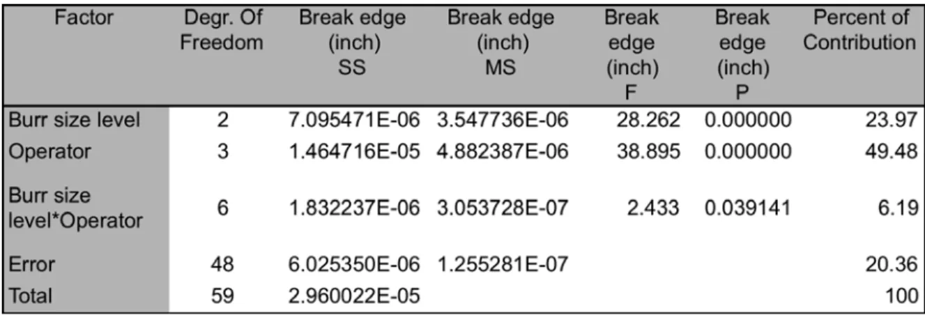
Table 6-1: Summary of ANOVA for break edge (Part A) ... 62
Table 6-2: Post-hoc tests for burr size (Part A) ... 64
Table 6-3: Summary of ANOVA for break edge (Part B) ... 67
Table 6-4: Summary of ANOVA for break edge (Part C) ... 70
Table 6-5: Summary of ANOVA for break edge (Part D) ... 73
Table 6-6: Alternative deburring processes ... 81
Table 6-7: Inconsistency of measuered break edge for samples from regular and coolant thru drill processes based on three main criteria ... 95
LIST OF FIGURES
Figure 2-1: Schematic of an air swirler ... 11
Figure 2-2: Schematic of consistent profile (a), and Inconsistent profile (b) around the hole ... 12
Figure 2-3: Break edge variation of holes around the part ... 12
Figure 3-1: Burrs Inside and outside of theoretical intersection [21] ... 14
Figure 3-2: Burr geometry [22] ... 15
Figure 3-3:Schematic of burrs created by plastic deformation [11, 24] ... 16
Figure 3-4: Schematic of burr formation in ductile and brittle material [26] ... 17
Figure 3-5: Three types of drilling burr of AISI 4118 (a) Uniform burr with a drill cap; (b) transient burr; (c) crown burr [18] ... 19
Figure 3-6: Two types of drilling burr of AISI 304L. (a) Uniform burr with drill cap; (b) crown burr [18] ... 19
Figure 3-7: Formation of different burr types during drilling [14, 19] ... 20
Figure 3-8: Formation of uniform burr [18, 19] ... 20
Figure 4-1: Edge quality classes [23] ... 23
Figure 4-2 : Effecting parameters of abrasive jet deburring process [34] ... 26
Figure 4-3: Schematic layout of abrasive jet machine [35] ... 26
Figure 4-4: Electropolish deburring tank.( courtesy Electro Glo Company)[15] ... 28
Figure 4-5: TEM deburring process[43] ... 30
Figure 4-6: Schematic of magnetic abrasive barrel finishing [39] ... 32
Figure 5-1: Process flow diagram ... 37
Figure 5-2: Fault tree graphically represents the events, which cause the inconsistency of break edge. ... 38
Figure 5-3: Air-swirler manual deburring steps ... 40
Figure 5-4: Air-swirler holes after applying grinding wheel ... 41
Figure 5-5: Hole edge after applying round file ... 42
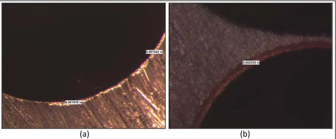
Figure 5-6: The wavy break edge created by the file (a) becomes smoother and larger after buffing operation (b) ... 42
Figure 5-7: Schematic of the holes on the samples ... 52
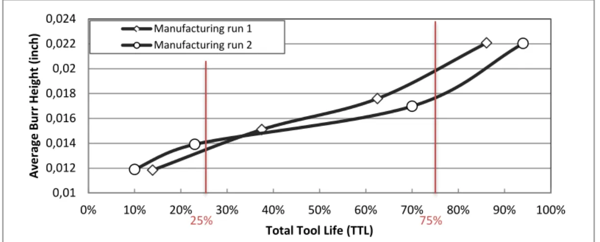
Figure 6-1: Observed burr height valused for the samples gathered from two manufacturing runs ... 57
Figure 6-2: Average Burr Height VS Total Tool Life ... 57
Figure 6-3: Remained burr on the edge after applying grinding wheel ... 59
Figure 6-4: Wavy break edge created after filing (A), Enlarged and smooth break edge after buffing (B) ... 59
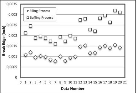
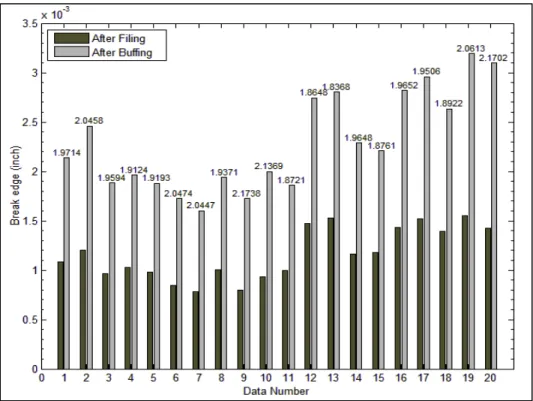
Figure 6-5:Observed break edge values for the filing and the buffing ... 60
Figure 6-6:Bar graph of observed break edges after the filing and the buffing operations ... 61
Figure 6-7: Effect of burr size level on break edge (Part A) ... 63
Figure 6-8: Effect of operator on break edge (Part A) ... 63
Figure 6-9: Effect of burr size and operator on break edge (Part A) ... 64
Figure 6-10: Residuals vs. predicted values (Part A) ... 65
Figure 6-11: Burr on the edge of the holes after free cut ... 66
Figure 6-12: Observed burr height values (Part B) ... 66
Figure 6-13: Effect of burr size level on break edge (Part B) ... 68
Figure 6-14: Effect of operator on break edge (Part B) ... 68
Figure 6-15: Effect of burr size and operator on break edge (Part B) ... 69
Figure 6-16: Residuals vs. predicted values (Part B) ... 69
Figure 6-17: Observed Burr height values (Part C) ... 70
Figure 6-18: Effect of burr size level on break edge (Part C) ... 71
Figure 6-19: Effect of operator on break edge (Part C) ... 72
Figure 6-20 : Effect of burr size and operator on break edge (Part B) ... 72
Figure 6-21: Residuals vs. predicted values (Part C) ... 73
Figure 6-22: Effect of burr size level on break edge (Part D) ... 74
Figure 6-23: Effect of operator on break edge (Part D) ... 74
Figure 6-24: Effect of burr size and operator on break edge (Part D) ... 74
Figure 6-25: Residuals vs. predicted values (Part D) ... 75
Figure 6-26: Producing small and repeatable burr ... 76
Figure 6-27: Reducing human error ... 79
Figure 6-28: Reciprocating file (Courtesy NSK) ... 80
Figure 6-29: The part and the tools ... 85
Figure 6-30: Average burr height of the parts and tool wear regions ... 86
Figure 6-32: Burr formation pattern in Region II ... 87
Figure 6-33: Temperature during cutting ... 88
Figure 6-34: Burr on three different holes of one part in Region III ... 90
Figure 6-35: Burr height on the holes produced by different methods ... 91
Figure 6-36: The drill caps created during current manufacturing process (a), vertical machining (b) and, using coolant thru drill (c) ... 92
Figure 6-37: Burr on large holes ... 93
Figure 6-38:Burr height on the large holes produced in horizontal and vertical positions ... 94
Figure 6-39: Burr on the holes of part A before (a) and after the process (b) and (c) ... 97
Figure 6-40: Burr on holes of part B before (a) and after the proces (b) ... 97
Figure 6-41: Burr on holes of part D before (a) and after the proces (b) ... 97
Figure 6-42: The prepared edge without burr and break edge (a) and the break edge around periphery after magnetic abrasive deburring (b) ... 98
LIST OF ABBREVIATIONS
AJM Abrasive Jet Machining ANOVA Analysis of Variances
CRIAQ Consortium de recherche et d'innovation en aérospatiale au Québec CW Continuous Wave
DOE Design of Experiments P &WC Pratt and Whitney Canada TEM Thermal Energy Method TTL Total Tool Life
INTRODUCTION
Regarding the development of new manufacturing techniques in aerospace industry in addition to the capacity of manufacturing complex geometries and difficult-to-machine materials, costumers raised novel demands. The manufacturers are expected to provide large quantities of high quality products in small dimensions. One of the most significant criteria of quality is that of the edges. Burr-free products with large break edge or radius are in favor. Staying competitive in global markets calls for robust strategies to tackle manufacturing and quality issues such as deburring. Canadian aerospace, as one of the world-leaders in the industry, has invested on various academic and industrial researches and projects related to deburring. MANU409, created by “Consortium de recherche et d'innovation en aérospatiale au Québec” (CRIAQ), was amongst the academic-industrial collaborative projects concerned deburring.
The objective of the CRIAQ Project “MANU409 Plan C: “Automatic deburring and part finishing” was to derive information regarding currently used deburring practices within Canada’s aerospace industry. The information included the techniques and the appliance stage of automation plus further-followed researches by companies and universities. Afterwards the information was classified to identify the research areas, which were more investable considering different potentials of the area.
Pratt and Whitney Canada (P&WC) has vested interest in this project to improve the current state of deburring, automation and quality of the products.
The topic of current study was extracted through technical surveys, cost estimation of the issues, and prioritization, which are addressed in the chapter of pre-project phase. The research was conducted in an industrial ambience and under academic supervision. The study aims to improve the consistency of deburring result of fuel nozzle parts.
The most important part in the hot section of an aircraft engine is the combustor. The main function of a combustor is to provide a reliable and smooth ignition by raising the temperature of the fuel and air mixture [1]. Stabilization of the flames is the most significant issue in combustion systems of aircrafts due to pressure change in combustion area. The shape of airflow plays an important role in stabilization of the combustion flames. In order to provide a homogenous
air-fuel mixture, which has a whirling flow pattern, air swirlers are employed as the most critical parts of the fuel nozzles [2]. These small components are involved with corrosion, high pressures, elevated temperatures, thermal and mechanical shocks through the combustion process[3]. The specific work condition of air swirlers necessitates the application of high standards of reliability and precision during manufacturing. The base material must exhibit outstanding mechanical properties at elevated temperature as well as corrosion resistivity. Hence, nickel alloys are favored choice for production of these parts. The parts are produced in small batch sizes. Numerous inclined holes are drilled through the parts, which intersect curved profile of the surface. The material properties and complex geometry of the part highly restrict the manufacturing. Furthermore, the machining is encountered with the issue of burr formation. Nickel-Base alloys are used in wide range of industries such as aerospace turbine engines, aircrafts, marines, industrial and vehicular gas turbines, nuclear reactors, steam power plants and many other structural elements that experience high temperatures [4]. The alloys induce severe issues in manufacturing, which limit production options, particularly with precise parts. Aircraft engine parts are expected to meet high standards of quality and precision, consequently the quality of machining, including the workpiece edges, becomes of concern [5]. The surface and edge quality are important as they affect the corrosion properties and fatigue life of the part in addition to airflow and combustion performance [2, 6].The difficult-to-machine nickel alloys generate large material projections during machining. One of the difficult-to-treat features of the high precision air swirlers is the edge characteristic of the drilled holes. The parts must be delivered burr-free with substantial break edge, which is provided through deburring action. The edge dressing process can cost up to one third of total manufacturing expense for some machined components [7, 8].
The outstanding properties of nickel alloys that make them an excellent choice for critical applications also have the result of diminishing their machinability. The high strength of Ni alloys is not decreased in elevated temperatures of cutting. Due to the poor thermal diffusivity of these alloys, the cutting tools endure the heat intense of the cutting. The adhesion and chemical reactiveness of nickel in addition to the presence of abrasive particles in the alloys dispose the tool to various types of wear[5, 9].
The manufacturing processes cause rough surface and undesired raised material on the edges which is called burr [10]. Dornfeld [11] defines burr as “a body created on a workpiece, which extends over the intended and actual workpiece surface and has a slight volume in comparison with the workpiece, undesired but to some extend, unavoidable”. The operators’ finger can be easily injured through assembly process as a result of presence of burrs and sharp edges. These small particles can part from the work piece during service and damage other components, exceptionally rotary and critical parts [7, 11, 12]. Although burr removal assure longer life cycle of the product, higher performance and simplicity of assembly and automation, it itself is a costly process. The cost of burr removal increases with geometrical complexity and high precision demands. For critical precise aircraft engine components the deburring can cost approximately 30% of total manufacturing cost [7].
Mechanical drilling is the most widely used process for producing holes through the manufacturing parts [13]. The drilling processes produce undesired bulge material on entrance and exit edges. The burr caused by plastic flow is defined as a burr, which must be removed for critical and precise parts [11].
1. Since the burr on the exit surface is considerably larger than the entrance burr, most drilling burr formation studies are focused on the exit burr [14]. The entrance burrs occur due to compression of material near the drill which leads to material flow along the tool edge (Poisson effect). Whereas the exit burr is typically an unsheared chip extended off the edge[14, 15].
Gillespie[16] was among the first researchers to offer a basic model for burr formation in drilling process. He also investigated the effect of tool geometry, cutting conditions and material properties over a wide range of experiment condition.
Stein [17] proposed a simple burr formation model in Titanium alloys. An inclusive burr formation mechanism was proposed by Kim [18] and Min [19] based on the study of drilling burr formation for low alloy steel AISI 4118 and stainless steel AISI 304. Kim [18] classified the burrs in three types : Uniform, Transient and Crown burrs. The basis of the classification is burr shape. Burr shape is of concern because the deburring cost is dependent upon the volume of the burr.
High toughness of nickel alloys in combination with excessive tool wear leads to formation of large burrs particularly in drilling operations[15]. Inconsistent burr profiles, small size of the features, restricted access, vicinity of critical faces and high cost of implementable techniques limit automated deburring options. Hence the parts are predominantly deburred manually. Currently most of deburring practices on precise parts are performed manually, which is the main source of inconsistency of the results due to repetitive action of the operator’s hand, visual capacity and time-consuming trial of each operator. Moreover, the deburring time of manual burr removal process increases exponentially with growth of burr thickness [20]. Hence, the phenomenon becomes more of concern for nickel alloy parts specially once they are supposed to meet high quality requirements.
Delivering high quality product is a paramount in the aerospace industry. Current study aims to establish proper manufacturing and deburring strategies to improve the deburring consistency of air swirlers. The improvement is achieved through tackling the issue of controlling burr formation as well as employing automated techniques to deburr the parts. Producing small and regular burrs during manufacturing is advantageous as it decreases the cost of the issue, facilitates the manual operation and is an essential step toward automation. Selecting an automated process to deburr difficult-to-reach features of the part is another important challenge, which is addressed in the research.
CHAPTER 1
PRE-PROJECT PHASE
Pratt & Whitney Canada has started to provide an inclusive idea of the deburring situation within the company, which comprises 4 main purposes for this initiative:
Provide an idea of the deburring state at P&WC
• Verify the largest issues which have potential of improvement
• Develop a proper base for prospect work and improvements, which incorporate graduate student research projects and future methods development
• Prioritize the extracted research areas and appropriate foundations based on current real industrial facts and needs existing at P&WC.
• Perform research on prioritized projects in collaboration with academic institutes.
The first 3 goals mentioned above were obtained by the student team, which was working on the project until January 2010 and the results were reported to Pratt &Whitney Canada.
The work performed was based on data collection and investigations. The result was an inclusive report including the current deburring practices within P&WC, the major problems in each department, root cause analysis and suggested solutions which, ended up to defining 22 projects concerning all departments. The investable research fields where proposed to the company for future resource supply of graduate students, which will follow the projects.
The investigation results provided research areas and largest issues related to all departments in shop floor. The third goal addressed above was prioritization of these projects. This aim should have been realized by finding a basis of comparison between the projects, which are not technically in the same level of consideration.
1.1 Methodology
First, the 22 projects were adjusted through assigning to different departments. Hence some of the issues are generic and most of departments are involved with them, the distribution of research areas within departments led to 37 projects including both specific and generic ones. After the adjustment, the prioritization criteria were formed to determine the precedence of the projects, which are not technically comparable. The cost of the issue, the customer opinion and the probability of success were selected as the basis of comparison. Each criterion should be
presented as meaningful number or category. This aim requires a consistent database, which can be built by a reliable survey. The data gathering and modification was based on real facts and numbers. Furthermore the customer opinion, the previous deeds and the future purposes were inclusively considered. All the collected information were classified and presented in different matrixes. After that, the classified data is analyzed, modified and prepared to use for calculation. The final calculation result was derived somehow that it could be representative of all the 3 criteria. Different parameters were applied and various graphics were demonstrated to prioritize the projects. Finally the results were discussed with the customer to confirm the prioritization. As mentioned, each criterion was presented as a number or category. The real cost is the only criterion which could be calculated directly. To unitize the 3 criteria, a general formula was presented. The formula reflects the customer opinion and probability of success as well as the production cost.
The production cost varies per department and production line. Thus the generic projects were adjusted through dispersing within different departments. Then the involved family parts were extracted and the associated part numbers were allocated to each project. The customer was consulted in order to conclude the customer priority. The customer point of view was applied in general formula, which the evaluation based on. The percentage of possibility of realization was determined considering shop floor and engineering consults.
The general formula, which is used to estimate the adjusted cost of issue for each individual project is as follows:
(1-1)
Production cost for specific part number = (Deburring time + Machining time) * (Production
line rate)
Customer priority = 3 values are applied depending on customer opinion (1=low, 5=medium,
10=high)
Probability of success = Percentage of possibility of realization based on shop floor and
engineering data
n = number of specific parts involved with project
1.1.1 Project Distribution
The 22 projects were proposed through previous work results, which contain the largest issues, root causes, suggestions and research areas. These projects covered both generic and specific issues within all departments. Due to different costs in various departments, common subjects were divided per department and family parts to alleviate the comparison. As a corollary the 22 projects were extended to 37 through assigning to different departments. For example tool wear is assigned to 4 different departments: Gas gen, Turbine and covers, Blades and Compressors.
1.1.2 Prioritization Criteria
To prioritize the adjusted projects, 3 main criteria were considered as the basis of decision: • Real cost
• Customer opinion • Probability of success
To conclude a consistent result from the general formula, it is necessary to clarify the part numbers associated with each project. The allocation of related part numbers was based on the following criteria:
• High Production volume
• High Production time (machining time, deburring time…etc.) • Part complexity
• Automatic deburring requirements • Deburring difficulties
1.1.2.1 Real Cost
The real cost of each project is assumed as the sum of production cost and quality cost for all associated part numbers in next two years (2010 and 2011). The mentioned terms will be clarified as follows:
Production cost
The production cost is the cost of production including the deburring cost and the machining cost depending on the project. There are different production lines within shop floor, which have different cost per hour. For each individual part number, the production cost calculated based on the deburring and machining hours and line rates. Then the production cost is multiplied by the production volume of next 2 years.
(1-2)
Quality cost
The quality cost is the cost of the scrap and rework. There are different quality lines within shop floor, which have different cost per hour as well. The rework cost is calculated based on quality line rates and rework hours. The scrap cost is added individually. Since no exact scrap cost and rework hours exist before manufacturing the parts, the rates of the year 2009 were used as reference. The calculated quality cost of each part number in 2009 is multiplied by the production volume of next 2 years.
(1-3)
Real cost per project
(1-4)
n=number of specific parts involved with the project
1.1.2.2 Customer Opinion
The customer opinion is based on the shop floor investigation. The operators and the supervisors are consulted in order to determine the level of importance of each project.
The customers evaluated the projects in three levels “High importance, Medium importance and Low importance”, and three values were allocated for these three levels as 10, 5 and 1 respectively. These values were used in general formula in order to modify the cost and apply the customer opinion in prioritization as well.
1.1.2.3 Probability of Success
The probability of success is determined as the percentage of realization possibility. Estimation of this percentage is based on the engineering consult, previous experiences and available methods for development. The percentage varies per project.
1.2 Result
Based on the addressed procedure the projects were prioritized. Following eight projects were selected for further research and investment:
1. Quality improvement of the received tools used for producing turbine blades 2. Improvement the consistency of the fuel nozzles’ deburring results
3. Improvement the deburring of balancing ream holes and interior holes 4. Tool wear control during manufacturing process of the turbine blades 5. Quality improvement of the received tools used for producing diffusers 6. Improvement the deburring of the countersink firtree of the turbine disc 7. Quality improvement of the received tools used for producing fuel nozzles
8. Optimization of machining or polishing process to overcome hand polishing difficulties in fan blades
The highest costs of the projects were assigned to project 1 to 3. High probability of success (more than 50%) in addition to the fact that the customers exposed very high interest in the addressed projects, enlist them in the top of the prioritized projects.
One can find the summary of the results for the last five projects in Table 1-1: Summarized prioritization results
Project Real Cost Customer
Priority
Probability of Success
4 Tool wear control (turbine blades) Very High Very high 30%
5 Quality improvement of received tools (diffusers) High Very High 50% 6 Improvement the deburring of firtree (turbine disc) High Very High 25% 7 Quality improvement of received tools (fuel nozzle) Very High High 50%
8 Mismatch (fans) High High 60%
Among these projects, I chose to conduct my research on Improvement the consistency of the fuel nozzles’ deburring results, which include manpower and manufacturing issues. The fuel nozzle parts are deburred manually though operators at this section face a repetitive manual action. Furthermore, the repetitive nature of the job decreases the precision of the manual process because the operator can easily lose the focus while working. On the other hand, the parts are very small with very tight tolerances and critical faces. This has extremely limited the manufacturing option to find solutions for parts with deburr, and the unit has the high amount of scrap in comparison to other manufacturing units within P&WC.
I decided to tackle this project not only due to the high technical and industrial importance but also due to the high academic value of addressing such a general issue that can make an important change in manufacturing though no need to say that the humane side of this project to provide a better working condition for the operators is priceless.
CHAPTER 2
PROBLEM DEFINITION AND APPROACH
Air-swirlers are part of hot section of aircraft engine, which their main purpose is to create airflow turbulence for optimal mixing of air and fuel as well as stabilizing the flames in combustion chamber. These critical small parts are made of heat resistant supper alloys of nickel, which exhibit high toughness and are prone to strain hardening. The airflow turbulence is achieved by blowing the air through the inclined holes, which intersects specific profiled surface. Figure 2-1 represents a schematic of an air swirler.
Figure 2-1: Schematic of an air swirler
During manufacturing process of these parts large raised material is produced on the edge of the holes due to the high toughness of nickel alloys. The raised material should be removed from the edge of the holes and edge should be treated somehow, it meet tight tolerance requirement of 0.003 to 0.015 inch break edge. Since the parts are under high thermal and fatigue loads, the break edge aims to decrease the micro cracks at the edge of the hole. Furthermore proper break edge can ameliorate the airflow of the part. The adjacent critical surface restricts the deburring action. The geometrical complexity of the parts and the variety of features restricts the parts to deburr by a one single deburring process. Thus the parts should be deburred in different sequences. Concerning all above the deburring process of air-swirlers is predominantly manual. Since these parts are inspected visually, the break edge is not measured after hand deburring. The main issue of these critical parts is inconsistency of deburring results. The inconsistency of break edge on air-swirlers can be addressed to tree various definitions:
• Profile inconsistency: The break edge is not consistent along the edge of the hole. The edge profile becomes thicker and then turns thinner around the hole. Figure 2-2 shows both consistent and inconsistent edge profiles.
Figure 2-2: Schematic of consistent profile (a), and Inconsistent profile (b) around the hole • Break edge variation from hole to hole: Similar holes of the part have different break edge
size. The average break edge around each hole is different from others around the part. Figure 2-3 schematically explains the break edge variation from hole to hole.
Figure 2-3: Break edge variation of holes around the part
• Air flow variation from part to part: An important purpose of the edge dressing of air-swirlers is amelioration of airflow. The break edge directly affects the airflow of the part. Thus with the inconsistent deburring results the airflow varies from part to part, although, it certainly remains in the acceptable range.
The inconsistency can be referred to two typical issues: inconsistent geometrical parameters of the burr, and unrobustness of the deburring process.
To tackle the inconsistency issue, literature review conducted on burrs on drilled holes and their type and formation. The survey continued on various deburring processes to find applicable ones.
The current deburring process was completely assessed. Moreover, the manufactured products were investigated to illustrate the current state of deburring results. Affecting parameters their weight factor were studied in different levels. With respect to the result of conducted experiments, different scenarios were designed to tackle the root causes. Some of the scenarios were selected to validate by complementary experiments considering the availability of equipment and project budget.
CHAPTER 3
BURRS IN DRILLED HOLES
Drilling is the most widely used process for producing holes through the manufacturing parts [13]. As a common issue, drilling, as well as other machining processes, produce undesired raised material on both entrance and exit edges. The raised material caused by plastic flow is defined as burr, which is necessary to be removed for critical and precise parts [11]. This chapter provides a comprehensive study on burr phenomenon, burr formation mechanism in drilling process, drilling burr classification, burr control in drilling process and burr measurement.
3.1 Burr phenomenon and characteristics
Burr in most dictionaries is defined as protruding, rough ridge raised on the a workpiece edge during manufacturing process. Ko [12] describes burr as unwanted raised material generated due to plastic flow during cutting and shearing operation. Gillespie [15, 20, 21] defines burr as “Plastically deformed material that is produced, because of machining or shearing, at workpiece edge”. In his definition any extended material beyond the intersection considered as a burr so the burr can place inside the intersection.
Figure 3-1: Burrs Inside and outside of theoretical intersection [21]
Burr can be characterized by various parameters such as geometry, type and mechanical properties. The difficulty of removing a burr is dependent to the burr characteristics[22].
The geometrical profile of the burr is described by Schäfer[23]. He explained the burr geometry as the following longitudinal and cross-sectional measurement categories.
• The burr height: the distance between the highest point of cross section and the ideal edge.
• Burr root radius: the radius of the circle positioned at burr root profile[23]. Other important properties of burr can be mentioned as
• Burr length: the length of the burr along the edge.
• Burr hardness: the harness of the burr measured at the root of the burr[15]. Figure 3-2 represents the burr geometry.
Figure 3-2: Burr geometry [22]
The burrs and other material projections such as flashes are produced by various physical mechanisms, which classifies them in six main groups. The first tree groups of protrusions are formed by plastic deformation[15, 22].
• Poisson burr
Lateral deformation of the workpiece edge along the tool cutting edge due to compression produce Poisson burr. These burrs are relatively small. The deformation is depending on applied force, workpiece and tool material.
• Rollover burr
When the exiting cutting edge bends the chip instead of shearing it, rollover burr is produced. The length and thickness of rollover burr is depended to cutting conditions and plasticity of workpiece material.
• Tear burr
Tear burr is formed when the chip is torn instead of being sheared. These burrs can occur in most cutting processes [15, 22, 24]. One can find the schematic of Poisson, Rollover and Tear burrs in Figure 3-3.
Figure 3-3:Schematic of burrs created by plastic deformation [11, 24] • Recast bead
Recast material is produced by re-solidification of molten metal on the edge. This protrusion is mostly appears in processes which material is removed by thermal mechanisms such as electro discharge machining and laser machining [24].
• Cut-off burr
Cut-off projections are burr-like overhangs, which are formed by parting the workpiece from bar-stock before the tool completes the separation cut [11, 22, 24]
• Flash
Flashes occur due to the flow of material into the gap between two mold halves, in the absence of proper clamping pressure during casting [15].
Gillespie[16, 24] and Pekelharing [25] were the first researchers who described the mechanism of burr formation. Hashimura [26] proposed a model in which the formation of burr is influenced by mechanical properties of the workpiece material as well as the geometrical profile
of both the tool and the workpiece. He describes the burr formation process in eight stages, which can be observed schematically in Figure 3-4. Since the crack propagation mechanism in ductile and brittle materials is different, the stages are described separately after crack initiation. Stage 1 describes the shear zone and chip flow in cutting process. Pre-initiation is the next stage in which, the workpiece edge starts to elastically deform or bend. Burr initiation described in stage 3 as a plastic deformation zone forms on the workpiece edge. This phenomenon is concurred with development of primary shear zone and plastic deformation zone around it. In stage 4, called pivoting, a considerable deformation occurs at workpiece edge, which can be visually observed. The burr is developed in stage 5 as a negative shear zone forms and the deformation zone enlarges to join the primary shear zone.
Figure 3-4: Schematic of burr formation in ductile and brittle material [26]
From the stage 5 on, the burr formation mechanism is defined based on material behavior. Stage 6 explains the crack initiation, which starts along the cutting line for ductile material (Stage 6-I). The ductile materials have larger fracture toughness. Thus, the crack initiates in primary shear zone and develops along the cutting line in stage 7-I. As the tool moves toward the workpiece
edge, the crack is expanded and the workpiece is deformed along the cutting line. In stage 8-I the crack separates the chip and leaves the deformed material as a positive burr on the workpiece edge.
In brittle material the crack propagation mechanism contrasts as the crack initiates in negative shear zone in stage 6-II. The crack starts at the tool tip and then it propagates along the negative shear zone. In stage 7-II the crack enlarges toward the pivoting point. Though, no large deformation is induced on the workpiece edge. In final stage (8-II), the crack parts the chip plus the material above the crack propagation line. This leads to formation of a fractured edge called negative burr.
3.2 Burr formation in drilling process
Since the main objective of this study is deburring of drilled holes, the literature survey is continued focusing on drilling burr formation.
In drilling operation, the burr forms on both entrance and exit surface of the part. Since the burr on the exit surface is considerably larger than the entrance burr most of drilling burr formation studies are focused on the exit burr [14]. The entrance burrs occur due to compression of material near the drill which leads to material flow along the tool edge (Poisson effect). Whereas the exit burr is unsheared chip extended off the edge[14, 15].
Gillespie[16] is among the first researchers who offered a basic model for burr formation in drilling process. He also investigated the effect of tool geometry, cutting conditions and material properties over wide range of experiment condition.
Stein [17] proposed a simple burr formation model in Titanium alloys. An inclusive burr formation mechanism is proposed by Kim [18] and Min [19] based on the study of drilling burr formation for low alloy steel AISI 4118 and stainless steel AISI 304. Kim [18] classified the burrs in three types : Uniform, Transient and crown burrs. The basis of the classification is burr shape. The burr shape is of concern because the deburring cost is dependent upon the size of the burr. He detected all the three types of burr in drilling AISI4118 and two types of burr in drilling AISI 304L, which one can find in Figure 3-5 and Figure 3-6 respectively.
Figure 3-5: Three types of drilling burr of AISI 4118 (a) Uniform burr with a drill cap; (b) transient burr; (c) crown burr [18]
Figure 3-6: Two types of drilling burr of AISI 304L. (a) Uniform burr with drill cap; (b) crown burr [18] Under certain cutting conditions, in both materials, a slight and thin burr with unvarying profile is formed around the edge of the hole, called the uniform burr. The uniform burr is observed with or without an attached drill cap. Another type of the burr, which is formed in both materials, is crown burr. The crown burr is larger than the uniform burr and it has variable profile around the hole periphery. In drilling AISI 4118 an additional type of burr is formed which is called the transient burr. This burr is formed in the transient stage as the burr tends to transform from uniform to crown burr. The formation of transient burr can be addressed to material properties such as stain hardening rate and toughness [18].
Afterward the burr formation mechanism is proposed based on the classification [18, 19]. Figure 3-7 demonstrate the mechanism of burr formation for the three types of the burr.
As the drill approaches the exterior face of the workpiece, a plastic deformation zone is formed under chisel edge because the chisel edge does not have a cutting edge. The deformed material under the chisel edge reaches the exit surface of the workpiece, while the material in vicinity of chisel edge is cut off by the cutting edge. As the plastic zone is diluted, the cutting action starts to transform to bending action at the center of the drill.. The plastic deformation zone expands from the center to the edge with advancement of the tool. The size of the plastic deformation zone is
mostly dependent to the thrust force of the drill. When the plastic deformation zone is thin enough, the fracture starts at the end of cutting edge forming a drill cap. The remaining material is bent along with the drill and forms thin, small height burr with a uniform shape around the edge (see Figure 3-8). Larger uniform burrs can be formed if the initial fracture occurs near the center of the drill. The primary fracture produce a secondary cap attached to the main drill cap. Then the secondary fracture takes place at the end of cutting edge and creates drill cap. Larger amount of material is pushed out ahead in this situation to create the uniform burr [19].
Figure 3-7: Formation of different burr types during drilling [14, 19]
Figure 3-8: Formation of uniform burr [18, 19]
Increasing the thrust force induces the plastic deformation earlier in the process. Thus thicker layer of material under chisel edge experiences the plastic deformation. This increases the maximum strain at the center region of the plastic zone. Subsequently the area becomes more brittle due to strain hardening and the initial fracture occurs at the drill center creating the crown burr with large and irregular profile around the hole.
Transient burr, which is observed in drilling AISI 4118, forms in the transient stage between the uniform and the crown burr. If the initial and second fractures occur simultaneously near the end of cutting edge and center of the drill, the transient burr is formed. This burr has larger uniform section with attached ununiform material around the hole [19].
CHAPTER 4
BURR REMOVAL AND DEBURRING PROCESSES
Deburring and edge finishing is an important step in manufacturing of precise and high quality parts. The key consideration toward selecting a reliable and cost effective deburring process is to identify the edge requirements. Although defining quality requirement is necessary, the process selection needs an overview of various processes and their capabilities. This chapter address the edge quality definitions as well as the deburring processes, which were selected based on tolerance, geometry, burr characteristics and base material of the target workpieces of this study.
4.1 Edge requirements
Burr definition as well as its classification criteria varies industry-by-industry and even company-by-company. Based on production needs and design requirements companies usually develop in-house standards for edge qualifications. While a “burr free” edge could be defined in some standards as no detection of loose material with aided vision, in some others it is defined as the edge condition which does not cause problems in either the next stages of assembly or its working performance [27].
Fortunately, several standards have been developed to classify required edge condition, and to provide appropriate drawing notation for engineers. One of them, which was developed by Gillespie [15] suggests seven steps of edge quality needed for the corresponding application and manufacturing processes. This standard will be explained with more detail in following. In contrast to this standard, which is based on verbal description of edge quality, the standard of Schäfer [23] provides a quantitative measure based on preferred values of edge condition. The values were chosen such that the number of classes was kept to nine. Figure 4-1 shows the parameters of burr quality in a coordinate system.
Other standards for evaluating edge quality have been developed [28, 29]; the former one defines acceptable burr parameters like its height based on code tables and work instructions in various case studies. The later developed by Kato divided quantitatively the edge quality into two critical and non-critical functionality conditions, each of which was subdivided into five and three quality states, respectively. Among the previously mentioned standard, which might be applicable in various industries, other standards like Berger’s [30], which covers many
applications in automotive industries, are more specific to the requirements of their corresponding industries.
Figure 4-1: Edge quality classes [23]
Based on [15]seven levels of required edge quality are defined. 1) Deburring is not required; although burr size might be larger than its limit, the producer leaves the burr as produced by the previous process. 2) Remove sharp edges; at this level edges are removed so to prevent them cutting operator skin, wires, etc. Important to note that burr size should be small enough such that part size does not exceed drawing limits. 3) Remove all visible burrs; all burrs that can be seen with unaided vision, and those which violate drawing limits should be removed. 4) Remove all
burrs visible at _x magnification; it implies that all burrs detectable by any optic methods and
lighting form with the specified magnification should be removed. 5) Break edges _× _ mm
minimum; which indicates the chamfer size as the maximum limit that no material should exceed.
6) Round edges _ to _ mm radius, in this level edge should be curved with maximum size specified. In contrast to level 5 in which the edge could be chamfered, blunted, etc, in level 6 curvature of the edge is important that chamfer is not acceptable. 7) Do not deburr; deburring is prohibited. While in level 1 deburring is an arbitrary process that is based on manufacturing, and economical requirements, in level 7 deburring is not allowed.
4.2 Hand deburring
Among 109 different deburring processes hand deburring is still the most widely used one. Although it may result in inconsistent products it is still desirable mostly owing to its flexibility
and versatility and also because it involves minimum floor space and investments. During hand deburring the operator could employ his creativity in improving the process, while he could choose the best approach and tool based on his experience.
Based on Gillespie [20] hand deburring is a cost effective option when:
1- Reaching and removing the burrs with other processes is difficult due to the geometry of the part.
2- The number of runs is of concern. For example when there are time limitations for few parts.
3- There are limitations for other processes. For example when the part size does not fit the deburring machine or when the part require precised deburring process which do not change the part dimensions or produces residual stress. In this case hand deburring process is the best choice.
4- Within a cycle hand deburring should be performed simultaneously to the other machining processes.
5- Process qualification is of concern.
In order to increase the effectiveness of the hand deburring process, certain considerations should be taken into account. Cost of the operation, edge requirements, available equipments, size of the burr and the accessibilities are listed as the fundamental factors of a manual deburring process, which should be considered perfectly in order to achieve an effective process. Furthermore choosing the appropriate deburring tools is essential in order to aim this goal. 23 tools which are introduced as effective tools by Gillespie [20] is shown in Table 4-1.
Table 4-1: Manual Deburring tools [20]
4.3 Abrasive jet deburring
Abrasive jet machining (AJM) as an effective non-conventional machining method can be applied to various difficult-to-machine materials, providing acceptable surface and close tolerance. Wide range of operations such as deburring, polishing, cutting, drilling etc., can be performed using the AJM process [31]. AJM as a deburring process does not apply mechanical forces. The part dimension does not change except the smooth radius which is created on deburred edge [32].
The abrasive jet machining material removal is obtained by directing accelerated abrasive particles on to the material surface. The fine abrasive particles are mixed with compressed air to provide a high velocity abrasive jet through a nozzle. The momentum of accelerated abrasive
particles in collision with target surface causes impingement erosion thus the material is removed from the surface [32-34].
These are various parameters that affect the generation of edge radius such as nozzle diameter, stand-off distance which is represented as the distance between the nozzle and the target surface, impingement angle, grain size, flow rate and jet height. Figure 1 demonstrates the effecting parameters of abrasive jet deburring process. Among the effecting parameters stand-off distance and nozzle diameter play a significant role in generation of edge radius[34].
Figure 4-2 : Effecting parameters of abrasive jet deburring process [34]
The AJM process can be implemented by abrasive jet machine or by an abrasive jet handpiece. Figure 2 represents a schematic layout of abrasive jet machine.
4.4 Electropolish and Burlytic Deburring
Electropolish deburring process employs an electrolyte solution to remove the metal from the target edge and surface[15]. The main concept of the process is based on concentration of electrolytic dissolution on the workpiece projections called anodic dissolution [36, 37]. Cathode rods and anode racks are hanged in the solution, making a circuit. The parts are connected to the anodic rack and cathodes are positioned near to workpiece[15, 36]. Low-voltage direct current, which is conducted through the electrolyte, polarizes the surface of the metal workpiece, creating a metal ion film. The metal ions diffuse through the film and change to metallic salts. Figure 3 shows a schematic electropolish deburring tank.
The ion film is thinner on surface and edge projections thus the current density is higher due to the lower electrical resistance. This phenomenon leads to preferential material removal on ridges and surface irregularities[15, 37]. The material on soaked surface is removed as well as raised material so the electropolished workpiece has bright and smooth surface[15].Hardness, toughness and other physical and chemical properties of the material does not affect the metal dissolution rate. Electrolyte concentration, inter-electrode gap thickness and electrical current voltage can be represented as the dominant machining parameters. The non-contact characteristic of electrochemical process eliminates all mechanical and thermal stress. Consequently the machined part does not feature any heat affected zone and residual stresses [36, 37].
The electropolish deburring process is appropriate for all conductive metals such as stainless steel, high nickel alloys, nickel silver, aluminum, brass, copper and zinc. Burrs with 0.0005 to 0.001 inch thickness can be removed with this process while the height of the burr does not affect the process. The edge stays sharp after deburring. Due to the low cycle time of the process, numerous processed parts per each work cycle and the fact that the process does not need any special tooling, electropolish can be employed for high-production parts. The process does not remove large and thick burrs thus it is applicable for precision parts with thin raised materials on the edge [15].
There are various types of solutions such as acid-based solutions, alkaline, cyanide, and metal electrolytes. The solution selection depends on the target alloy. Previously acid-based solutions
were the most common but at present the most widely used deburring solutions are proprietary solutions.[15]
Figure 4-4: Electropolish deburring tank.( courtesy Electro Glo Company)[15]
Burlytic process is an electrochemical process, which has the same process principles as elecrtropolish. Burlyte, a non-aqueous electrolyte with high electrical resistance properties, is the advantage that makes the Burlytic deburring different from other electrochemical processes. The electrolyte is available in two types: Burlyte A or Burlyte C. Both Types have near-neutral PH and they are non-fuming, odorless, and quite safe to handle. The process owes its inexpensiveness and simple tooling requirement to the edge-seeking nature of the electrolyte. However, at very difficult-to-access edges, such as narrow intersecting holes, tooling becomes more complex. Although it should be mentioned that, cathode distance does not affect the process quality [38].
Burlyte electrolyte acts selective. The selective electrolyte idea is based on the theory of the mechanism of electrical current transportation.
Ionic movement in electrolytes can be addressed to three mechanisms: • Diffusion: Ions transport due to concentration gradient.
• Convection: Ions transport through mechanical flow of electrolyte. • Migration: Ions transport because of electrical potential gradients.
In low viscosity solutions with high conductivity, such as aqueous electrolytes, ion diffusion is the dominant transportation mode. In contrast, in Burlyte electrolyte, ion transportation via convection and diffusion is very slow due to the low dielectric constant compared with aqueous-based electrolytes and high viscosity respectively. Thus the dominant transportation mechanism of ions in Burlyte is migration. The electrical field is stronger on burrs, so, ions move faster[38]. The process is appropriate for high-precision small parts as well as large and less delicate parts. Since the process is very quick and the electrolyte acts selective the burr on the edge is removed but the surface remains unaffected. However surface finish improves due to the fact that microroughnesses of the surface become smooth[38].
4.5 Cryogenic Deburring (Via Liquid Nitrogen)
Cryogenic deburring uses cryogenic temperature (accomplished by using liquid nitrogen) to make the thin raised material fragile. The embrittled burr is removed by blasting solid rubber particles or by the use of tumbler or vibratory machine[39, 40]. Since the material experiences very low temperature during the process, the time set up is extremely important due to avoid damaging the workpiece structure. As the time exceeds a certain limit the part embrittles as well as the raised material, which is not preferred. Thus the burr should be thin enough to freeze quickly before the part reaches its embrittlement temperature. Since the parts core should not meet cryogenic temperature, the preferable materials for the process are the materials with low thermal conductivity such as rubbers, plastics, zinc and aluminum alloys [39]. Recently due to new technology development the process is applicable for many types of engineering materials, even high grades of stainless steel and various super alloys[41].
The process can be very precise depending on the media or blast particles. No change in part dimension is reported in previous deeds and investigations. Burrs are completely removed without any dust or residue remaining on the part. Process, itself, is repeatable and reliable due to the fact that it benefits automated system. Since the process variables such as temperature, time, tumble speed, media velocity, and media size can be set up on machine, the process benefits high flexibility through combination of parameters depend on the shape, size, and base material of the workpiece[39, 40, 42].
4.6 Thermal Energy Deburring
Since 1960, Thermal Energy Method (TEM), have been commercially practiced as an unconventional deburring and finishing process. The process burns away burrs and flash using combustion. The combustion process provides required energy for processing [43]. The intense heat generated through combusting fuel gas and oxygen vaporizes material projection on both inner and outer edges and surfaces [15].The combustion occurs only when all the three crucial items including fuel, oxygen, and heat are present. The cycle will be incomplete if one of the three is eliminated during the process. Figure 4-5 shows TEM deburring process.
The target workpiece is placed on an index table in a sealed under pressure chamber. The pressurized gas mixture around the part ignites through high-voltage electrical spark and creates approximately 3000 deg. Celsius temperature within 2-3 micro seconds [15, 43]. Material projections root restrict the heat flow due to their small thickness. Thus the heat is accumulated in the burr instead of propagation within workpiece body and leads to automatic ignition of the burr [43]. As the flame gets to surface of the part, it is extinguished. Body of the workpiece is not burned because disparate the burrs they do not have high surface to mass ratio. During the process, raised material combines with oxygen, creating oxide of the parts parent material, which in most cases needs to be removed [15, 43].
The process is flexible since the two main variables, gas mixture and pressure chamber, regulate the amount of generated heat and heat wave intensity and lasting time. These main variables can be selected somehow, not only large or small burrs are removed from the workpiece, but also appropriate break edge is provided on the part [43]. The richer the mixture and the higher the pressure, the larger burr is removed [15, 43].
Significant improvement is observed in the process when the gas is used as the deburring media. Employing the gas is beneficial in comparison to other deburring processes in which the small abrasive particles are used as deburring media because, the gas can enclose confined areas, which abrasive particles are not able to reach[44-46] .
TEM is an appropriate process when high production volume of parts is of concern. The process can be employed to remove thin burrs and flash from parts for wide range of geometry, particularly for internal intersecting holes and external edges with critical adjacent surface. The process is applicable for all types of metals and alloys, although some of them are more difficult to be treated. The best performance of the process is observed through deburring metals with medium thermal conductivity. The process can affect material structure and cause imbrittleness, phase transformation or carbon deposition at grain boundaries [15, 43, 47]. For material with low heat resistant and high thermal conductivity factor, the heat cannot be accumulated in burrs so little or no deburring action is provided [47].
4.7 Magnetic Abrasive Deburring
Magnetic abrasive deburring is a mechanical burr removal process, which benefits the presence of magnetic field to remove the unwanted raised material from the workpiece[48]. Magnetic field is employed in order to provide effective control of the deburring process, which makes the process capable of deburring advanced engineering material and difficult to finish alloys[49]. Furthermore the process can produce round edge with desired radius[50]. The micro-cutting force created by movement of hard abrasive grains is controlled by intensity of magnetic field. This prevents the surface damages generated by excessive penetration of the abrasive particles into the workpiece surface and, provides high surface finish [49].
Various machines and abrasive brushes designed to satisfy the quality requirement of different part geometries. The shape and the size of the particle, the shape and the place of magnetic
inductor, vibration mode of magnetic field, magnetic field density have significant effect on edge quality and surface roughness[48, 49, 51-53]. However the concept of controlling abrasive particles via magnetic field is not limited to magnetic brushes. In various mass finishing processes the concept employed in order to reach difficult-to-finish areas without getting the abrasive media stuck in the fine unreachable areas. In Figure 4-6 one can find the Schematic of magnetic abrasive barrel. The magnetic inducer can be rotary or oscillating. As the polarity changes, the magnetic pins spin or vibrate. Through the moving of the media, the tiny pins shot the workpiece with the induced magnetic force which, removes the edge projections[39, 54]. However the process will be more effective by tumbling or turning the parts against the moving media[39]. More complex geometries can be deburred with the process compared to conventional medias. Moreover, the short cycle time of the process prevents part from losing dimension requirement and makes it cost effective [54, 55].
Figure 4-6: Schematic of magnetic abrasive barrel finishing [39]
4.8 Laser Deburring
Application of lasers in deburring process goes back to 1978 [56]. Numerous applications have been announced. However, no remarkable achievement in applying lasers for deburring is reported yet. Illinois Institute of Technology Research Institute in Chicago in the 1980s conducted the research on applying lasers in deburring process for the first time. However the results were not satisfactory. Generation of a heat-affected zone is the limiting point in applying this method for many operations [57].
However numerous advantages of laser deburring such as its short process time, flexibility, preciseness, ability to pursue the profile edges and the fact that it is a noncontact process, still serve it as an option in deburring certain materials [57].
In general lasers are categorized as continuous wave (CW) and pulse systems. Continuous wave systems produce (emit) continuous waves, whereas pulse systems perform through discrete pulses. Pulsed lasers are themselves broken down to long and short pulse systems [57].
The best example for laser deburring can be mentioned as its usage in Injection nozzles for ink jet printing [58]. The problem was the tardiness of the process when applying a single laser for deflashing and deburring the holes, and on the other hand the high cost of applying lasers when performing parallel process.
Nunobiki [59]successfully laser deburred 304 stainless steel. Lee [60-62] applied laser deburring on low carbon and stainless steels. They found laser deburring process more effective for producing a constant chamfer. This was attributed to the non-sensitivity of the process to the variation of burr size or tool force, owing to the noncontact nature of the lasers.
CHAPTER 5
METHODOLOGY
The main objective of this study is improving the consistency of deburring results of the air-swirlers. To aim this goal, a comprehensive study of current state of these parts, their manufacturing, and their deburring process is necessary. The investigation forms an inclusive idea about the inconsistency of deburring results, analyzes root cause of the issue, and provides us with a basis of comparison, which can be used further. An experimental survey has been conducted on the actual production parts at shop floor. The experiments design based on Design Of Experiments methods [63-65], which included root cause analysis to find the affecting parameter as well as their weight factor and interactions. Afterwards the second series of experiments have been planed and conducted on the parts to investigate the practical feasibility of the alternative processes to improve the consistency. In this chapter one can find the detailed explanation of the above procedure.
5.1 Investigation of current state of the parts
The current manufactured air-swirlers were investigated to clarify the state of the inconsistency, the root cause of the phenomenon, affecting parameters, and the weight factor of each parameter. This essential investigation aims better understanding of current process as well as facilitation of selecting next step to improve the process consistency. Thus, based on Design Of Experiment principles [63-65], the experiments were planned, designed, and conducted. Four part numbers were investigated during the experiments. The four part numbers are identified as the part A, B, C, and D.
Part A is the most difficult-to-handle due to its geometrical complexity and size, which leads to more sever burrs. Part B and C are smaller and they have major geometrical similarities such as equal edge requirements and almost equal hole size. Although a small difference in their manufacturing process makes their burr properties different. Part D is the easiest-to-handle due to its simple geometry and modified manufacturing process, which leads to slight burrs around the accessible holes.
![Figure 3-3:Schematic of burrs created by plastic deformation [11, 24] • Recast bead](https://thumb-eu.123doks.com/thumbv2/123doknet/2346601.35028/30.918.269.651.264.527/figure-schematic-burrs-created-plastic-deformation-recast-bead.webp)
![Figure 3-4: Schematic of burr formation in ductile and brittle material [26]](https://thumb-eu.123doks.com/thumbv2/123doknet/2346601.35028/31.918.134.791.439.884/figure-schematic-burr-formation-ductile-brittle-material.webp)
![Figure 3-7: Formation of different burr types during drilling [14, 19]](https://thumb-eu.123doks.com/thumbv2/123doknet/2346601.35028/34.918.229.688.339.661/figure-formation-different-burr-types-drilling.webp)
![Figure 4-2 : Effecting parameters of abrasive jet deburring process [34]](https://thumb-eu.123doks.com/thumbv2/123doknet/2346601.35028/40.918.105.783.355.645/figure-effecting-parameters-abrasive-jet-deburring-process.webp)