MATHEMATICAL PROGRAMMING OF PEIRCE-SMITH CONVERTING
ALESSANDRO NAVARRA
D´EPARTEMENT DE MATH´EMATIQUES ET DE G´ENIE INDUSTRIEL ´
ECOLE POLYTECHNIQUE DE MONTR´EAL
TH`ESE PR´ESENT´EE EN VUE DE L’OBTENTION DU DIPL ˆOME DE PHILOSOPHIÆ DOCTOR
(G´ENIE INDUSTRIEL) AO ˆUT 2013
c
MATHEMATICAL PROGRAMMING OF PEIRCE-SMITH CONVERTING
pr´esent´ee par : NAVARRA Alessandro
en vue de l’obtention du diplˆome de : Philosophiæ Doctor a ´et´e dˆument accept´ee par le jury d’examen constitu´e de :
M. ANJOS Miguel F., Ph.D., pr´esident
M. SAVARD Gilles, Ph.D., membre et directeur de recherche M. AJERSCH Frank, Ph.D., membre et codirecteur
M. STUART Paul, Ph.D., membre M. MUNZ Richard J., Ph.D., membre
In memory of our lost friend and mentor, Ralph Harris. . .
The following two years were devoted primarily to my Master’s degree in applied math-ematics at McGill University. Although my Master’s research was not directly related to Peirce-Smith converting, I was briefly exposed to mathematical programming during the coursework. Ralph and Wing trusted my intuition that mathematical programming could be used to optimize converting schedules, and led me to Dr Jo¨el Kapusta (Formerly of Air Liquide), who also had an interest in Peirce-Smith converting.
At ´Ecole Polytechnique, I have been privileged by two outstanding (and patient) super-visors. Firstly, Frank Ajersch had been a longtime associate of Ralph, and a distinguished expert in Peirce-Smith converting. Frank agreed to have me as a student, and connected me to my other supervisor, Gilles Savard, an expert in mathematical programming. Ulti-mately, it was Gilles’ description of the course offerings that convinced me to study in the D´epartement de math´ematiques et de g´enie industriel. Indeed, it has been an honour to study under such talented and passionate professors, including Guy Desaulniers, Dominique Orban, Andr´e Langevin, Charles Audet and Louis-Martin Rousseau.
In the spring of 2007, shortly before my doctoral studies, Ralph transferred from McGill University to the Royal Melbourne Institute of Technology. Even from a distance, Ralph was expected to have a leading role in my doctoral research. Yet he passed away suddenly on July 12th
, less than two months before the beginning of my doctoral studies.
Following the tragic passing of Ralph, it was unclear if the mathematical programming of Peirce-Smith converting would still be a viable line of research, especially since Wing had accepted a position at CANMET and was no longer available. However, Jo¨el and Air Liquide agreed to support my work, in spite of the dramatic change in personnel.
Having now completed my doctoral studies, my sincere acknowledgement and gratitude are due to Ralph and Wing who introduced me to Peirce-Smith converting, as well as Jo¨el, Frank and Gilles who supported me through difficult times. Financial support was provided by Air Liquide and the Fonds qu´eb´ecois de la recherche sur la nature et les technologies.
R´ESUM´E
Le convertissage par m´ethode Pierce-Smith (PS) est l’´etape cl´e de la production de cuivre et du nickel. Cette op´eration se poursuit par des ´etapes s´equentielles et pr´esentent un cas id´eal pour la programmation math´ematique. Ce travail d´emontre les complexit´es thermochimiques et les ´etapes du convertissage au moyen d’un programme lin´eaire (PL) en nombres entiers mixtes. Ceci est la premi`ere fois que le convertissage PS est abord´e dans un cadre de program-mation math´ematique et repr´esente un avancement majeur de l’application de la recherche op´erationnelle aux ´etapes de production des fonderies de cuivre et de nickel.
Les r´esultats d´emontrent que le cadre math´ematique est fonctionnel, et peut ˆetre utilis´e quotidiennement pour la gestion optimale des s´equences d’op´eration de l’´elaboration de cuivre et de nickel. Le cadre est flexible quant `a la d´efinition des contraintes du syst`eme et de la fonction objective. Cette flexibilit´e ´evoque la formulation de divers modes d’op´eration des fonderies. Le cadre pourra ˆetre exploit´e en forme de logiciel industriel que les fonderies pour-raient utiliser pour coordonner la production journali`ere, et de varier leur mode d’op´eration selon les conditions de l’usine et du march´e.
Le cadre a ´et´e formul´e suivant une m´ethodologie qui est typique de la programmation math´ematique, mais qui n’avait jamais ´et´e adapt´ee au convertissage PS. Premi`erement, le probl`eme se pose en forme g´en´erale. En effet, Le probl`eme de convertissage consiste de la coordination des convertisseurs PS avec d’autres op´erations dans la fonderie afin de max-imiser la production durant une p´eriode fixe, tout en respectant les contraintes chimiques, volum´etriques et thermiques. Deuxi`emement, les diverses composantes et dimensions du syst`eme sont repr´esent´ees par des structures alg´ebriques g´en´erales; c’est-`a-dire, des ensem-bles, des param`etres et des variables. Troisi`emement, ces composantes sont li´ees de telle mani`ere `a ce que la formulation puisse ˆetre support´ee par des techniques de r´esolution.
Les techniques de r´esolution par la programmation lin´eaire (PL) en nombres entiers mixtes sont bien ´etablies. Par contre, il a ´et´e n´ecessaire d’introduire des simplifications pour pou-voir r´esoudre le probl`eme des convertissages par l’adoption d’un cadre hypoth´etique de PL en nombres entiers mixtes. En consid´erant la vaste gamme de probl`emes qui ont ´et´e d´ej`a abord´ees dans ce type de cadre, il semblait raisonnable que le convertissage PS n´ecessiterait seulement des simplifications mineures.
tidienne de la production. Suivant les succ`es du travail actuel, des efforts superficiels provo-queront des changements majeurs dans les op´erations journali`eres des fonderies de cuivre et de nickel.
ABSTRACT
Peirce-Smith (PS) converting is central to the production of copper and nickel, and is a lucrative, yet previously undeveloped, context for mathematical programming. The thermo-chemical complexities of PS converting have now been represented within a mixed-integer linear program (MILP). This is the first time that PS converting has been treated within a mathematical programming framework, hence a major advancement in the operations re-search of copper and nickel smelters.
The MILP framework is now functional, and can be used to construct optimal daily production schedules. The framework offers flexibility in the definition of system constraints and objective functions. This flexibility can accommodate the formulation of alternative modes of operation for smelters. The MILP framework can now be marketed as industrial software, to produce optimal daily schedules, and allow smelters to change their mode of operation in accordance to plant and market conditions.
The framework has been created using a methodology that is typical of mathematical programming, but which had never been adapted to Peirce-Smith converting. Firstly, the problem has been posed in appropriately general terms; indeed, the PS Converter Problem is to coordinate Peirce-Smith converters with other objects in the smelter, so as to maximize production within a fixed period of time, while respecting chemical, volumetric and thermal constraints. Secondly, the various components and dimensions of the system have been rep-resented using general algebraic structures, such as sets, parameters and variables. Thirdly, these components have been related to each other in a manner that can be supported by solution techniques.
The solution techniques for MILP are well established. However, it was initially unclear what degree of simplification would be required in order to fit the PS Converter Problem into a hypothetical MILP framework. Given the vast scope of problems that have already been treated using MILP, it seemed plausible that the PS Converter Problem would require only minor simplifications.
The new MILP framework has indeed required some simplification. More precisely, the framework imposes an artificial rigidity on two classes of temperature variables: nominal offgas temperatures, and skimming temperatures. These simplifications can be considered minor, since there are existing software tools that do not even treat these quantities as
TABLE OF CONTENTS DEDICATION . . . iii ACKNOWLEDGEMENTS . . . iv R´ESUM´E . . . v ABSTRACT . . . vii TABLE OF CONTENTS . . . ix
LIST OF TABLES . . . xiii
LIST OF FIGURES . . . xv
NOMENCLATURE . . . xviii
LIST OF APPENDICES . . . xxvi
CHAPTER 1 PEIRCE-SMITH CONVERTING AND EXTRACTIVE METALLURGY 1 1.1 Importance of PS Converting . . . 1
1.1.1 Global Presence . . . 1
1.1.2 Interdisciplinary Divide . . . 1
1.2 Overview of Extractive Metallurgy . . . 3
1.2.1 Mineral Concentration . . . 3
1.2.2 Pyrometallurgical and Hydrometallurgical Extraction . . . 4
1.2.3 Hybridization of Pyro- and Hydrometallurgical Extraction . . . 7
1.2.4 Further Divisions within Extractive Metallurgy . . . 8
1.2.5 Extraction of Copper and Nickel . . . 10
1.3 Overview of PS Converting . . . 13
1.3.1 PS Converting as a Bessemerization Process . . . 13
1.3.2 Matte Converting Reactions . . . 16
1.3.3 PS Converting Technology . . . 19
CHAPTER 3 CHARACTERIZATION OF CHEMICAL STREAMS IN PS SYSTEMS 38
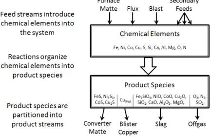
3.1 Elements, Species and Streams . . . 38
3.1.1 General Representation of Chemical Converting . . . 38
3.1.2 General Representation of PS Converting . . . 40
3.2 Species-Based Distribution of Mass, Volume and Heat . . . 42
3.2.1 Mass Distribution Within a Process Stream . . . 42
3.2.2 Volume Distribution Within a Process Stream . . . 44
3.2.3 Heat Distribution Within a Process Stream . . . 45
3.2.4 Heat Distribution Across Several Process Streams . . . 49
3.3 Characterization of Feed Streams . . . 51
3.3.1 Furnace Matte . . . 51
3.3.2 Fluxes and Secondary Feeds . . . 53
3.3.3 Blast . . . 56
3.4 Characterization of Product Streams . . . 58
3.4.1 Regime-Dependence of Product Species . . . 58
3.4.2 Mass Distribution Across the Product Streams . . . 61
3.5 Flow Mechanisms . . . 63
3.5.1 Streams, Actions and Flow Mechanisms . . . 63
3.5.2 Modulated Charging and Discharging . . . 66
CHAPTER 4 MILP FORMULATION OF THE PSC PROBLEM . . . 69
4.1 Gantt Structure . . . 69
4.1.1 Assignments . . . 69
4.1.2 Dependencies . . . 71
4.2 PS Converters as State-Machines . . . 73
4.2.1 States and Transitions . . . 73
4.2.2 Converting Actions . . . 79
4.3 Intermediate Computations . . . 80
4.3.2 Blast Elemental Masses . . . 83
4.3.3 Product Species Masses . . . 84
4.3.4 Blast Heat . . . 86
4.3.5 Offgas Heat . . . 87
4.3.6 Discharge Heat . . . 89
4.3.7 Environmental Heat Losses . . . 92
4.4 Forward State Computation . . . 93
4.4.1 Retained Feed Masses . . . 93
4.4.2 Retained Product Species Masses . . . 94
4.4.3 Retained Heat . . . 95
4.5 Feasible Converter Transitions . . . 96
4.5.1 Direct Transition Constraints in General Linear Form . . . 96
4.5.2 Bath Composition Constraints . . . 98
4.5.3 Volume Constraints . . . 106
4.5.4 Temperature Constraints . . . 108
4.5.5 Indirect Transition Constraints in General Linear Form . . . 112
4.6 Global Objectives and Constraints . . . 113
4.6.1 Optimization of Nongaseous Flows and of Transition Types . . . 113
4.6.2 Limiting of Nongaseous Flows and of Transition Types . . . 114
CHAPTER 5 THE SINGLE-CYCLE PSC PROBLEM AND SAMPLE COMPUTA-TIONS . . . 116
5.1 Adaptation of the PS MILP Formulation . . . 116
5.1.1 Topological and Initial Conditions . . . 116
5.1.2 Critical Overlap Decomposition . . . 118
5.1.3 Dominance Condition for the Critical Stage . . . 122
5.1.4 Maximizing the Productivity of a Single Converting Cycle . . . 125
5.2 Software Systems . . . 129
5.2.1 AMPL and CPLEX . . . 129
5.2.2 Excel and VBA . . . 130
5.3 Sample Computations . . . 133
5.3.1 Sample Computations for a Copper PS Converter . . . 133
5.3.2 Sample Computations for a Nickel-Copper PS Converter . . . 141
CHAPTER 6 EXTENSIONS OF THE PSC MILP FORMULATION . . . 148
6.1 Nonlinearity of the PS Converter Problem . . . 148
LIST OF TABLES
TABLE 1.1 Summary of Bessemerization processes . . . 16 TABLE 1.2 Species present in matte, in increasing order of thermodynamic stability 18 TABLE 1.3 SO2 content of offgas streams, calculated as a function of blast
en-richment, assuming oxygen efficiencies from 85 to 95%, and dilution factors ranging of 2 to 2.5 . . . 23 TABLE 3.1 Density and temperature response parameters for product species in
Peirce-Smith systems [59, 60] . . . 46 TABLE 3.2 Description levels for fluxes and secondary feeds . . . 53 TABLE 3.3 Elemental composition of a revert stream k [66] . . . 54 TABLE 3.4 Density and temperature response parameters [59, 60] for j ∈ ˆSk,
where k is a revert stream that was formed by the accumulation of flue dust, having the elemental composition given in Table 3.3 . . . 55 TABLE 3.5 Stability of regime-dependent species the General Nickel-Copper PSC
Formulation . . . 59 TABLE 3.6 Stability of regime-dependent species in the Simplified Copper PSC
Formulation . . . 60 TABLE 3.7 Decomposition of feed and product streams with respect to converting
actions . . . 63 TABLE 4.1 Classification of the converter variables included in the current MILP
implementation . . . 82 TABLE 4.2 Default values for mass-fraction bounds . . . 103 TABLE 5.1 User input for sample copper PSC computations (System Parameters) 134 TABLE 5.2 User input for sample copper PSC computations (Converting Cycle) 134 TABLE 5.3 User input for sample copper PSC computations (Feeds) . . . 136 TABLE 5.4 User input for sample copper PSC computations (Temperatures) . . 137 TABLE 5.5 Feed tonnages from copper PSC computations . . . 139 TABLE 5.6 User input for sample nickel-copper PSC computations (System
Pa-rameters) . . . 143 TABLE 5.7 User input for sample nickel-copper PSC computations (Converting
Cycle) . . . 143 TABLE 5.8 User input for sample nickel-copper PSC computations (Feeds) . . . 144 TABLE 5.9 User input for sample nickel-copper PSC computations (Temperatures)144 TABLE 5.10 Feed tonnages from nickel-copper PSC computations . . . 147
LIST OF FIGURES
FIGURE 1.1 Relationship between mine sites, scrap yards and extractive
metal-lurgical plants . . . 4
FIGURE 1.2 Stages of pyrometallurgical and hydrometallurgical extraction . . . 5
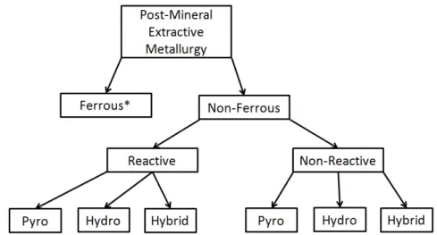
FIGURE 1.3 Classification of post-mineral extractive metallurgical processes . . 8
FIGURE 1.4 Flow diagram for a conventional copper smelter . . . 11
FIGURE 1.5 Input and output streams of a Bessemerization process . . . 13
FIGURE 1.6 Bath volume during Slag-Blow stage (a) prior to blow, (b) after blow, (c) after skimming . . . 17
FIGURE 1.7 Newly commissioned Peirce-Smith converter at the Harjavalta Oy Smelter [38] . . . 20
FIGURE 1.8 Interior of a Peirce-Smith converter . . . 20
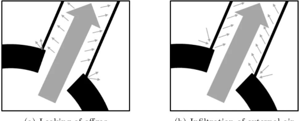
FIGURE 1.9 Interaction between offgas and external air . . . 22
FIGURE 1.10 Interior of a Hoboken converter (side-view) . . . 24
FIGURE 1.11 Relationship between O2 enrichment and the demand for cold charge 24 FIGURE 1.12 ALSI Technology [7] . . . 24
FIGURE 1.13 Converter aisle at the Xstrata Nickel Smelter in Sudbury [46] . . . 26
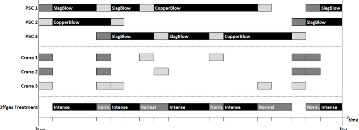
FIGURE 2.1 Gantt chart of a Peirce-Smith converting aisle. The schedule begins at time tBegin and ends at time tEnd. The discrete events are marked with short dashes along the time axis. . . 27
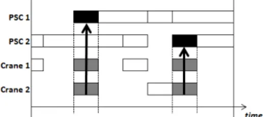
FIGURE 2.2 Depiction of assignment dependency. In this case, the charging of an empty converter (black) requires the assistance of two cranes (grey). 30 FIGURE 2.3 Venn diagram describing the object classes of a Peirce-Smith system. The PSC class is a critical state-machine class. . . 32
FIGURE 2.4 Converter transition diagrams for (a) typical copper PS systems, and (b) typical nickel PS systems. The transition types are num-bered (1) InitialCharge, (2) SlagBlow, (3) Skim, (4) Recharge, (5) CopperBlow, (6) ScrapCharge, and (7) EndCycle. . . 33
FIGURE 2.5 Converter transition diagrams for (a) Simplified copper PS systems, and (b) Simplified nickel PS System. The transition types are la-beled (I) BeginSlagBlowStage, (II) ContinueSlageBlowStage, and the remainder are numbered as in Figure 2.4. . . 35
FIGURE 2.6 Generic converter transition . . . 35
FIGURE 4.2 Bounds are placed on the overall bath composition and individual stream composition, placing restrictions prior to charging, following
blowing and following discharging . . . 98
FIGURE 4.3 Volume evolution during converter transition . . . 107
FIGURE 4.4 Temperature evolution during converter transition . . . 108
FIGURE 5.1 EndPreviousCycle and EndCurrentCycle transitions . . . 116
FIGURE 5.2 Converter transition diagrams to adapt (a) typical copper PS sys-tems, and (b) typical nickel PS System to the SC-PSC formulation. The transition types are numbered (1) InitialCharge, (2) SlagBlow, (3) Skim, (4) Recharge, (5) CopperBlow, (6) ScrapCharge, and (7) EndCycle. . . 117
FIGURE 5.3 Critical Overlap Decomposition . . . 119
FIGURE 5.4 Offgas treatment capacity limiting production to no more than two simultaneous blowing actions . . . 119
FIGURE 5.5 Shortage of ancillary objects at (a) the beginning of cycle and (b) the end of the cycle . . . 120
FIGURE 5.6 Optimal production schedules for two-converter systems, having dif-ferent dCrit to dCycle ratios . . . 123
FIGURE 5.7 Optimal production schedules for a three-converter system, having different dCrit to dCycle ratios . . . 124
FIGURE 5.8 Construction of the productivity ratio objective for the SC-PSC Problem . . . 128
FIGURE 5.9 Interaction between Excel and the optimization platform which con-sists of AMPL and CPLEX . . . 131
FIGURE 5.10 First page of the user interface for sample copper PSC computations 133 FIGURE 5.11 Objective functions from sample copper PSC computations . . . . 138
FIGURE 5.12 Optimal Gantt charts from sample copper PSC computations . . . 139
FIGURE 5.14 Bath temperature from sample copper PSC computations . . . 140 FIGURE 5.15 Converter transition diagrams for limited access to the smelting
fur-nace. The transition types are numbered (1) InitialCharge, (2) Slag-Blow, (3) Skim, (4) Recharge, (5) SlagBlowAndSkimWithoutAny-MoreFeedMatte, (6) ExtendProductionCycleWithoutAnyMoreFeed-Matte. . . 142 FIGURE 5.16 First page of the user interface for sample nickel-copper PSC
com-putations . . . 142 FIGURE 5.17 Objective functions from sample nickel-copper PSC computations . 146 FIGURE 5.18 Optimal Gantt charts from sample nickel-copper PSC computations 146 FIGURE 5.19 Bath volume from sample nickel-copper PSC computations . . . . 147 FIGURE 5.20 Bath temperature from sample nickel-copper PSC computations . 147 FIGURE 6.1 Splitting of a product stream during a discharge . . . 149 FIGURE 6.2 Simplified geometry of a converter that has no mouth . . . 157 FIGURE 6.3 Extraction of Topological Information from a Gantt Chart . . . 160
Ai Assignments of class i
Aij Assignments of object (i, j)
APSC Assignments (transitions) of the PSC class
C Object classes
Dik Dependency clauses for assignment type k of class i
DPSCk Dependency clauses for transition type k of the PSC class
E Chemical elements
Ek Chemical elements constituting stream k
F Flow mechanisms
FBlast Blast flow mechanisms
FCh Flow mechanisms acting on charge streams
FDCh Flow mechanisms acting on discharge streams
FFeed Flow mechanisms acting on feed strems
Fk Flow mechanisms acting on stream k
FNGBlow Flow mechanisms acting on nongaseous streams that are fed during
blowing actions
FOffgas Offgas flow mechanisms
FProd Flow mechanisms acting on product streams
FM Modulated flow mechanisms
FM
Ch Modulated flow mechanisms acting on charge streams
FM
DCh Modulated flow mechanisms acting on discharge streams
FMSM Modulated and semi-modulated flow mechanisms
FMSM
Ch Modulated and semi-modulated flow mechanisms acting on charge
streams FMSM
DCh Modulated and semi-modulated flow mechanisms acting on discharge
streams FSM
Semi-modulated flow mechanisms FSM
FSM
DCh Semi-modulated flow mechanisms acting on discharge streams
FUM Unmodulated flow mechanisms
FUM
Ch Unmodulated flow mechanisms acting on charge streams
FUM
DCh Unmodulated flow mechanisms acting on discharge streams
LDTrans
PSC Direct transition feasibility clauses implemented in general linear form
LTrans
PSC Transition feasibility clauses implemented in general linear form
R Reaction regimes
Rj Reaction regimes in which species j is stable
S Species
SFeed Species that constitute the feed streams
Sk Species that constitute stream k
SNGProd Species that constitute the nongaseous product streams
SProd Species that constitute the product streams
SRgProd Species that constitute the product streams, and whose stability
de-pends on the reaction regime Ti Assignment types of class i
TPSC PSC transition types
TPSC,Crit PSC transition types that constitute the critical stage (relevant to the
SC-PSC problem)
TPSC,Empty PSC transition types that cause the object converter to be empty
TPSC,IDCh PSC transition types that include a discharging action, but do not
result in an empty converter
TPSC− k PSC transition types that may precede a transition of type k T−
PSC,Crit PSC transition types that occur prior to the critical stage (relevant to
the SC-PSC problem) T+
PSC,Crit PSC transition types that occur after to the critical stage (relevant to
the SC-PSC problem)
Z Streams
ZBlast Blast streams
ZBlow Streams that are red or removed during the blowing action
ZCh Streams that are fed during the charging action
ZDCh Streams that are removed during the discharging action (is identical to
ZProd)
ZFeed Feed streams
ZNG Nongaseous streams
l− Predecessor of assignment l l+ Successor of assignment l Parameters
d Upper bound on the duration of assignments
dkBlow, dkBlow Minimum and maximum duration of the blowing action, during a tran-sition of type k
dkCh, dkCh Minimum and maximum duration of the charging action, during a tran-sition of type k
dkDCh, d
k
DCh Minimum and maximum duration of the discharging action, during a
transition of type k
dki, dki Minimum and maximum duration of segment i, during a transition of type k
eO Oxygen efficiency
φkj Volume fraction of gaseous species j in the blast of a transition of type k
˙hk
Blast Rate at which heat is introduced into the bath as part of the blast,
during a the blowing action of a transition of type k hobj(l)
, hobj(l) Lower and upper bound on the bath heat that is permitted in obj(j) hPSCj
, hPSCj Lower and upper bound on the bath heat that is permitted in PSC j nAsgni Upper bound on the number of assignments that a member of class i
may undertake in the current schedule
nCrit Maximum number of converters that may be simultaneously in the
critical stage (relevant to the SC-PSC problem) ni Number of members in object class i
˙ mk
iBlast Mass rate at which element i is introduced into the bath as part of the
Mi Atomic mass of element i
Mj Molecular mass of species j
ρj Density of species j
ρNorm
j Density of gaseous species j, as measured under Normal conditions
ρk Density of stream k
t Upper bound on the assignment completion times of the current sched-ule
tBegin Time at which the current schedule begins
tEnd Time at which the current schedule ends
TBlastk Blast temperature of transition type k
TBlowk, TBlowk
Minimum and maximum bath temperature that is permissible during the discharging action of a transition of type k
TDChk Bath temperature at the end of the discharging action of a transition
of type k (relevant when k is an intermediate discharge transition type, k ∈ TPSC,IDCh)
TDChk, TDChk
Minimum and maximum bath temperature that is permissible during the discharging action of a transition of type k
Tobj(l)
, Tobj(l) Lower and upper bound on the bath temperature that is permitted in obj(j)
TOffgask Nominal offgas temperature of transition type k
TPSCj
, TPSCj Lower and upper bound on the bath temperature that is permitted in PSC j
ujk, ujk Minimum and maximum number of units that can be delivered through
flow mechanism j, during a transition of type k
vjk, vjk Minimum and maximum volume that can be delivered through flow
mechanism j, during a transition of type k
vBlowk,PSCj Maximum bath volume that is permitted in PSC j during the blowing
action of a transition of type k
vChk,PSCj Maximum bath volume that is permitted in PSC j during the charging
action of a transition of type k
vuj Volume that is carried by a unit of a modulated flow mechanism j vj
u Maximum volume that can be carried by a unit of a semi-modulated
flow mechanism j ˙vNormk
Blast Volumetric blast rate, during the blowing action of a transition of type
k, measured under Normal conditions
transition of type k wBlowk
Hj , w
Blowk
Hj Minimum and maximum specific heat content of species j that is
per-missible during the blowing action of a transition of type k wBlowk0
Hk , w
Blowk0
Hk Minimum and maximum specific heat content of stream k that is
per-missible during the blowing action of a transition of type k0 wBlowk0
ik , w
Blowk0
ik Minimum and maximum weight fraction of element i that is permissible
in stream k of a converter that is completing the blowing action of a transition of type k0
wBlowk0
jk , w
Blowk0
jk Minimum and maximum weight fraction of species j that is permissible
in stream k of a converter that is completing the blowing action of a transition of type k0
wBlowk0
k , w
Blowk0
k Minimum and maximum weight fraction of stream k that is permissible
in the bath of a converter that is completing the blowing action of a transition of type k0
wDChk
Hj Specific heat content of species j during the discharging action of a
transition of type k (relevant when k is an intermediate discharge tran-sition type, k ∈ TPSC,IDCh)
wDChk
Hj , w
DChk
Hj Minimum and maximum specific heat content of species j that is
per-missible during the discharging action of a transition of type k wDChk0
Hk , w
DChk0
Hk Minimum and maximum specific heat content of stream k that is
per-missible during the discharging action of a transition of type k0 wDChk
i , w
DChk
i Minimum and maximum weight fraction of element i that is permissible
in the bath of a converter that is completing the discharging action of a transition of type k
wDChk0
k , w
DChk0
k Minimum and maximum weight fraction of stream k that is permissible
in the bath of a converter that is completing the discharging action of a transition of type k0
w◦ki , w◦ki Minimum and maximum weight fraction of element i that is permissible in the bath of a converter that is to begin a transition of type k w◦kik0, w◦kik0 Minimum and maximum weight fraction of element i that is permissible
in stream k of a converter that is to begin a transition of type k0 w◦kjk0, w◦kjk0 Minimum and maximum weight fraction of species j that is permissible
in stream k of a converter that is to begin a transition of type k0 w◦kk 0, w◦kk 0 Minimum and maximum weight fraction of stream k that is permissible
in the bath of a converter that is to begin a transition of type k0 wOffgask
Hj Specific heat content of offgas species j, as measured at the nominal
offgas temperature of transition type k wRef
Hj Specific heat content of species j, as measured at the reference
temper-ature, 298.15 K wRef
Hk Specific heat content of stream k, as measured at the reference
temper-ature, 298.15 K
Variables
βl
Rgk Regime determinant that is 1 iff the bath of obj(l) is in reaction regime
k at the end of transition l βlk
Suppl0k0 Assignment support determinant that is 1 iff assignment l is of type k,
and is supported by assignment l0 that is of type k0 βl
Typek Assignment type determinant that is 1 iff assignment l is of type k
dCrit Duration of the critical stage (relevant to the SC-PSC problem)
dCycle Duration of the converting cycle (relevant to the SC-PSC problem)
dl Duration of assignment l
dlBlow Duration of the blowing action of transition l (is equal to d
l 4)
dlCh Duration of the charging action of transition l (is equal to d
l 2)
dl
DCh Duration of the discharging action of transition l (is equal to d
l 6)
dl
i Duration of segment i of transition l
dl
◦ Duration of time between the end of transition l− and transition l
hl
Blast Heat that is blown into the melt as part of the blast of transition l
hl
Ch Heat that is introduced into obj(l) as part of the charge streams of
transition l
hlDCh Heat that is removed from obj(l) as part of the discharge streams of
transition l
hlEnvi Heat that is lost from the bath of obj(l) to the environment during
transition l
mliProd Mass of element i within the product streams of transition l
ml
jProd Mass of species j within the product streams of transition l
ml
jRetProd Mass of species j within the retained product streams of obj(l) at the
end of transition l ml
k Mass of feed stream k that participates in transition l
ml
Retk Mass of feed stream k retained in the bath of obj(l) at the end of
transition l
tl Completion time of assignment l Typel Assignment type of assignment l
ujl Number of delivery units used during transition l to carry srce(j) via mechanism j, to or from obj(l)
vjl Volume of srce(j) delivered during transition l via mechanism j, to or
from obj(l) wBlowl
i Weight fraction of element i in the bath of obj(l) at the end of the
blowing action of transition l wBlowl
ik Weight fraction of element i in stream k of obj(l) at the end of the
blowing action of transition l wBlowl
jk Weight fraction of species j in stream k of obj(l) at the end of the
blowing action of transition l wBlowl
k Weight fraction of stream k in the bath of obj(l) at the end of the
blowing action of transition l wDChl
i Weight fraction of element i in the bath of obj(l) at the end of the
discharging action of transition l wDChl
k Weight fraction of stream k in the bath of obj(l) at the end of the
discharging action of transition l
wi◦l Weight fraction of element i in the bath of obj(l) at the beginning of transition l
wik◦l Weight fraction of element i in stream k of obj(l) at the beginning of transition l
wjk◦l Weight fraction of species j in stream k of obj(l) at the beginning of transition l
wk◦l Weight fraction of stream k in the bath of obj(l) at the beginning of transition l
A.4 Failure to Adapt Conventional Scheduling Algorithms to PS Converting . . 186 A.5 Pyrometallurgical Alternatives to PS Converting . . . 187 APPENDIX B OVERVIEW OF MIXED INTEGER LINEAR PROGRAMMING . 190 B.1 Linear Programming and the Simplex Method . . . 190 B.2 Alternatives to the Simplex Method . . . 196 B.3 Expansion of a Solved Linear Program . . . 198 B.4 Incorporation of Integer Variables . . . 202 B.5 Incorporation of Categorical Variables . . . 206 B.6 Importance of Linear Fractional Programming . . . 210 APPENDIX C AMPL FILES USED FOR THE SC-PSC PROBLEM . . . 213 C.1 mod File . . . 213 C.2 Sample dat Files . . . 233 C.3 run Files . . . 262
CHAPTER 1
PEIRCE-SMITH CONVERTING AND EXTRACTIVE METALLURGY
1.1 Importance of PS Converting 1.1.1 Global Presence
Peirce-Smith (PS) converting is applied in roughly 75% of the world copper production and 50% of the world nickel production, within 25 countries and 6 continents [1, 2, 3]. For copper, this amounts to roughly 12.7 million tons per year, at 8 000 USD/ton [4]. For nickel, this amounts to roughly 1.05 million tons per year, at 17 600 USD/ton [5].
Peirce-Smith converting is formally an operational bottleneck [6]. It is preceded by smelt-ing furnaces that act as a buffer; the furnaces can normally provide feed exceedsmelt-ing the im-mediate capacity of the converters. PS converting then sets the tempo for the downstream operations. Improvements in the PS converting thus translate into overall benefits to the entire smelter.
PS converting is widely accepted by an industry accustomed to its simplicity [7, 8, 9], and has not undergone any radical changes since its inception in 1909 (Appendix A.1). Instead, it has had a series of incremental ancillary equipment and operation strategies (Appendix A.2), which have been supported through modeling and simulation techniques (Appendix A.3).
There are several technologies competing with the PS converter, such as the Hoboken siphon converter, and various continuous converting technologies (Appendix A.5). Even if these alternatives are destined to replace PS converting, it would take decades to phase out existing PS installations. Incremental improvements of PS will therefore remain lucrative.
Technological stagnation is detrimental in such a competitive environment with the po-tential for incremental improvement. But this stagnation can be overcome with reliable and justifiable decision-making. Herein, software tools have become invaluable to investigate the avenues of process change [10, 11, 12].
1.1.2 Interdisciplinary Divide
In the year 2013, the pyrometallurgical community is not well-versed in mathematical programming. Likewise, industrial engineers, mathematicians and computer scientists do not
ical programming. For example, few metallurgists have ever heard of the Simplex Method (Appendix B.1).
Pyrometallurgists are adept at solving continuous mathematical problems, as they have a fairly robust background in differential and integral calculus. On the other hand, they have a limited understanding of discrete mathematical problems, as they are not usually trained in algorithm design. This gap in education has limited metallurgists with regard to “systems thinking”, which is now accepted as a major underpinning of process design and operations management [14].
In very rough terms, calculus is to continuous solutions spaces, what algorithm design is to discrete solution spaces; the essential link between continuous and discrete problems is provided by mathematical programming. Thus mathematical programming can build upon the existing competencies of pyrometallurgists, expanding toward the design of algorithms.
PS converting is a context that blends continuous and discrete mathematics, hence de-manding the use of mathematical programming. This context is particularly attractive to nonferrous pyrometallurgists, because of its historical importance, and because of its con-tinued pervasiveness in industry. The management of PS converting presents a powerful motivation for the pyrometallurgical community to expand its mathematical abilities beyond the confines of matrix algebra and calculus.
This document emphasizes a particular kind of mathematical programming: mixed integer linear programming (MILP), described in Appendix B. Chapters 2-4 adapt the general MILP paradigm to the context of Peirce-Smith converting. But as demonstrated in Chapter 4, this adaptation requires some degree of simplification, i.e. linearization. Chapter 5 demonstrates sample calculations for simplified instances, and illustrates the type of numerical results that can be provided by the MILP framework. Finally, Chapter 6 describes the inherent nonlinearity of the PS converting, and discusses future work in algorithm development.
The current work has resulted in the first MILP framework to manage PS converting systems. It offers a degree of abstraction and adaptability that has not been seen by the extractive metallurgical community at large. This framework is now the backbone of new methodologies that will improve existing operations, and the design of new plants. By con-sidering the defining features of Peirce-Smith converting and its broader industrial charac-teristics, this work will incite new lines of multidisciplinary research in engineering, applied mathematics and related fields.
1.2 Overview of Extractive Metallurgy 1.2.1 Mineral Concentration
Extractive metallurgy is the set of separation and extraction processes, leading to the production and refinement of metals. Some of these processes are performed at mine sites, and are collectively referred to as mineral concentration.
Within a given mine site, these concentration processes are housed in an industrial build-ing called a concentrator, which produces one or more concentrates. As depicted in Figure 1.1, the concentrates are sent to extractive metallurgical plants, where the metals are chem-ically extracted.
Some of the extractive metallurgy is performed at the mine sites, within the concentrators, and some is performed in the extractive metallurgical plant. The division between mineral concentration and the subsequent extraction varies from metal to metal, and depends on the nature of the ore that is being mined. Generally, an extractive plant is a logistical hub to a network of mine sites, but may be integrated with a local mine, and with railroad or port facilities.
Ores can be either rocky or clay-like. Rocky ores include copper and nickel sulfides, as well as iron oxides. (Iron sulfides are geologically common, but they are not economically viable as ore because iron oxides are cheaper to process and are sufficiently abundant). Clay-like ores include nickel laterites and aluminum lateritic bauxites.
To process rocky ores, concentrators include grinders to break the ore into fine particles that are amenable to further processing; such concentrators are often called “mills”. To process clay ores, concentrators include roasting ovens to disassemble hydrate complexes and to eliminate volatile species. Both types of concentrators apply separation techniques to divide the valuable minerals from each other, and from the waste gangue.
Figure 1.1: Relationship between mine sites, scrap yards and extractive metallurgical plants
Froth floatation is a particular separation technique in which chemically active bubbles are passed through a slurry, selectively drawing minerals into the skins of the overflowing bubbles[15]. Froth floatation is especially important for sulfide concentration, including cop-per and nickel-bearing minerals. Other separation techniques used in mineral concentrators may be driven by gravity or by magnetic phenomena.
Concentrates are the primary feed for extractive metallurgical plants. But many of these plants accept recycling scrap as secondary feed. The metal products are consumed within the manufacturing and construction industries (Figure 1.1). Some of these products are sent for additional metallurgical treatments, including additional refining and alloying, as well as deformation, heat and surface treatments. Some of the byproducts of extractive metallurgy are sent to chemical industries, which may actually include other metallurgical sectors. 1.2.2 Pyrometallurgical and Hydrometallurgical Extraction
There are traditionally two approaches to extract the valuable metals from concentrates. Firstly, pyrometallurgical extraction is the release of metals via high-temperature reactions occurring in molten or vaporous process streams. Secondly, hydrometallurgical extraction is the release of metals via dissolution reactions occurring in aqueous process streams. Figure 1.2 gives an overview of these two traditional approaches.
The feed preparation often includes drying and/or roasting. Concentrates are normally shipped as wet powder to avoid ignition during transportation. After arrival at the extractive plant, the concentrates may be heat-dried so as to favour the subsequent reactions. The term “roasting” is applied when the amount of heat exceeds that of drying, but is insufficient to cause bulk melting of the concentrate.
(a) Pyrometallurgical extraction
(b) Hydrometallurgical extraction
Figure 1.2: Stages of pyrometallurgical and hydrometallurgical extraction
A roasted concentrate is called a calcine. Certain oxidation or reduction reactions may be performed during roasting. In some pyrometallurgical processes, surface melting is allowed to occur, causing the concentrate to fuse into larger particles or pellets; such calcines are often called sinters [15].
A pyrometallurgical extraction plant is commonly referred to as a smelter. These plants are regarded for their high reaction rates and cost-effectiveness, particularly when dealing with high-grade concentrates, and consumer scrap. Hydrometallurgical plants generally have slower reaction rates than smelters but, for the processing of complex and low-grade mineral concentrates, hydro plants are usually more cost-effective and less polluting [16]. Hydromet-allurgical plants are also known for the high-purity of their product.
There are two central operations within a smelter: smelting and converting (Figure 1.2a). Etymologically, “smelting” has the same germanic origins as “melting”[17]. The former has come to imply the complete melting and partial reaction of metal-bearing solids; occasion-ally, it can imply the evaporation (fuming) of a metal-bearing solid. Once in a fluid state, the smelted material is vulnerable to the intense chemical transformations that constitute converting, and the subsequent reactions that are less intense and which constitute refining. Within a hydrometallurgical plant, there are three central operations: leaching, converting
may be molten/vapourous as in pyrometallurgical converting, or they may be dissolved as in hydrometallurgical converting. Without sufficient mobility, the rapid reactions are limited to the surfaces, and the bulk of the feed reacts very slowly if at all. Smelting and leaching initiate the metal-bearing material for bulk pyrometallurgical and for bulk hydrometallurgical reactions, respectively.
PS converting is the most common type of converting in copper and nickel smelters [1, 2, 3]. Its main feed is molten furnace matte. “Furnace” refers to the smelting furnaces that precede the converters, and “matte” implies a sulfide phase. PS converting is a type of Bessemerization, which is the forced oxygenation of a molten metal-bearing stream (See Subsection 1.3.1). Essentially, the furnace matte is “converted” into a dense metal-rich fluid, a light slag fluid, and a SO2-bearing offgas.
The most common type of hydrometallurgical converting within the copper and nickel industry is solvent extraction (SX), [18, 19]. Solvent extraction is a process by which the PLS is mixed with an organic liquid that preferentially absorbs certain ionic species; the organic solution is not soluble in the leaching solution, and eventually disengages from it, carrying away the absorbed species. Thus the initial PLS is “converted” into separate aqueous and organic phases.
SX is the main alternative of PS converting. Although PS converting has pyrometellur-gical alternatives as well, which are distinguished through their vessel geometries, and their various mechanisms for receiving feed and discharging products; these topics are discussed in Subsections 1.3.3 and Appendix A.5.
A final pyrometallurgical conversion gives a molten metal product, which is usually subject to further refining (Figure 1.2a). The initial refining stages are sometimes applied directly to the molten metal, which is pyrometallurgical refining. This is often called “fire refining”, par-ticularly in copper production [15]. Other refining treatments are applied after the metal has been cast or granulated into solid form; such treatments may be performed in an installation
separate from the smelter, i.e. a metal refinery.
The division between pyrometallurgical converting and pyrometallurgical refining is not always clear. When the feed is highly metallic, either “converting” or “refining” might be the appropriate term, depending on the context. Loosely speaking, converting reactions are deemed to be more intense than refining reactions.
A final hydrometallurgical conversion gives a final pregnant solution. Thus, an additional step is necessary in order to recover the valuable metal(s) from the solution, (Figure 1.2b). This is sometimes accomplished through the application of an electric current (electrowinning, EW), or by manipulating the composition, temperature and pressure to reduce the metal solubilities (precipitation) [16]. The resulting metal is often sufficiently pure not to require refinement, except in cases where ultra-purity is desired.
The metal recovery stage places a clear division between hydrometallurgical converting and the subsequent refining (Figure 1.2b). This division is not present in the pyrometallur-gical approach (Figure 1.2a), hence the vagueness between pyrometallurpyrometallur-gical converting and refining.
Figure 1.2 is a rather crude summary of pyro- and hydro-metallurgical extraction, which suits the purposes of this document. Actual plant designs feature feedback cycles, scavenging of waste-streams, etc. and varying degrees of redundancy. A more advanced treatment would explore these secondary features.
1.2.3 Hybridization of Pyro- and Hydrometallurgical Extraction
Pyro- and/or hydrometallurgical extraction methods are sometimes hybridized. Techni-cally, these hybrid processes include a partial metallurgical conversion as part of the feed preparation for a subsequent metallurgical extraction.
One reason for hybridization is to implement the respective advantages of pyro- and of hydro-metallurgical extraction. Pyrometallurgical smelting and converting may be suc-ceeded by hydrometallurgical dissolution and electrowinning, thus combining pyro-intensity and hydro-purity; this is typical of nickel smelters [3, 16]. In other cases, a hydrometallurgical approach is used to simplify a complex feed prior smelting, e.g. the simplification of bauxite ores in preparation for aluminum production [20]. As long as there is a smelting operation, the extractive plant may still be referred to as a smelter.
Figure 1.3: Classification of post-mineral extractive metallurgical processes
streams are solidified and granulated in order to apply froth floatation, thus creating several outgoing streams; to continue the conversion, it is then necessary to reactivate the streams, either by heating or dissolving. This is done in certain nickel sulfide smelters that produce copper and cobalt byproducts [3, 16].
In the coming decades, there is likely to be an increasing degree of hybridization within the metallurgical industry. The simple and high-grade ores are being depleted, and the traditional approaches are not as successful on the remaining ores [21]. This continues to motivate new approaches that are optimized for complex and low-grade ores.
1.2.4 Further Divisions within Extractive Metallurgy
Distinctions have been made between mineral concentration, and the subsequent pyromet-allurgical, hydrometallurgical and hybrid extraction processes. There are further divisions in extractive metallurgy, namely ferrous vs non-ferrous, and reactive vs non-reactive (Figure 1.3).
Engineering literature and academic curricula treat ferrous metallurgy independently from the rest of metal production because of the pervasiveness of iron in nature, and the relative ease with which it can be extracted. Only the densest deposits of iron oxide are worth exploiting, rendering iron sulfides and other iron compounds undesirable.
Iron is actually the second most common metal in the Earth’s crust, yet it represents 95% of the world’s metal production tonnage [21], largely because of the form and concentration
in which it is found. Aluminum is more common in nature than iron and has a higher strength-to-weight ratio, but it is far more expensive than iron. Iron has thus evolved to be the multipurpose metal used throughout construction and manufacturing, whereas the non-ferrous metals are selected only when their special properties are essential.
In themselves, iron and steel alloys can fill a wide range of manufacturing demands via the addition and removal of alloying elements, as well as surface and thermal treatments. In these cases, iron is the main component, and it is often small amounts of non-ferrous metals that bring forth the special properties of the given alloy. Indeed, much of non-ferrous metal consumption is in steel alloys; for example, 60% of the global nickel production is intended for stainless steel and related alloys [22].
Historically, there has been considerable adaptation of concepts and technology from ferrometallurgical extraction into non-ferrous extraction. The influence has been in both re-active and non-rere-active processing, and especially in the pyrometallurgical branches. Peirce-Smith converting is one example of non-ferrous technology that evolved from ferrous tech-nology (See Section 1.3.1).
Figure 1.3 makes a distinction between the extraction of reactive metals and non-reactive metals, which are each propagated into pyro, hydro and hybrid processes. In this context, “reactive” specifically implies the tendency to form oxides when smelted or leached in regular air environments [23]. Metals such as copper, nickel and cobalt may be smelted/leached without pervasive oxidation, and are hence non-reactive, likewise for gold, silver and other noble metals. Aluminum, magnesium, zinc, tin and the like require special equipment or processing to protect them from air environments during smelting/leaching.
The traditional way to extract a reactive metal from a concentrate is to pyrometallurgi-cally reduce the oxide concentrate or calcine in the presence of carbon (carbothermic reduc-tion); this is still widely practiced for iron and tin. This is also common for zinc production, although 80% of primary zinc is now extracted through hydrometallurgical means [24]. In this context “reduce” implies the introduction or restoration of electrons to the metal atoms which, in chemistry jargon, is the opposite of “oxidize”.
Incidentally, the treatment of iron oxides employs coke (roasted coal) to carry away the bonded oxygen. Ferrous extractive metallurgy is therefore a form of reactive pyrometallurgy. The carbothermic reduction of iron oxides results in a carbon-saturated molten metal, known as pig iron. The conversion of pig iron into steel is similar to PS converting, as discussed in Subsection 1.3.1.
solved in a bath of molten cryolite Na3AlF6 held at roughly 1000 C. The dissolved aluminum
ions are reduced into metal as electricity is passed from a consumable graphite (carbon) anode, through the melt, and into the outer graphite shell that acts as the cathode. This constitutes the Hall-Heroult process [20], and is a form of carbo-electrothermal reduction. The liquid aluminum is heavier than the cryolite solution, and is therefore drained from the bottom of the cell.
Aluminum is the prime example of a reactive metal where the traditional carbo-reduction is inadequate. It is Nature’s most abundant metal, yet prior to the Hall-Heroux process (1886), it had been more valuable than gold [25]. There are also other reactive metals, such as magnesium and titanium, which form sizable portions of the terran crust, yet their cost precludes them from prominence in manufacturing and construction.
Copper, nickel and other non-reactive metals have a tremendous advantage over reactive metals. They can be processed as molten matte [15]. Sulfur and iron may be carried away by blasting an oxidizing stream through the matte, which is the principle behind Peirce-Smith converting and related technology.
Generally in extractive metallurgy, there is a technological challenge to render the metal and its bonding elements (sulphur, iron, oxygen, chlorine, etc.) sufficiently mobile to permit separation [15, 16]. The problem is more complicated for reactive metals, especially when the bonds are too strong for carbothermal reduction. The rest of this document focuses on copper and nickel extraction, which are non-reactive metals, and thus do not suffer from these complications.
1.2.5 Extraction of Copper and Nickel
The world primary copper supply consists almost entirely of sulfide ores, rich in chal-copyrite CuFeS2. The nickel supply is divided evenly between sulfides rich in pentlandite
Figure 1.4: Flow diagram for a conventional copper smelter
that the laterite-based nickel production will exceed the sulfide-based nickel production [2]. Within a concentrator, copper and nickel sulfide ores undergo milling and froth floata-tion. On the other hand, nickel laterites undergo reduction roasting. Various pyro- and hydrometallurgical extractions are available for each of these ore classes.
Figure 1.4 depicts a typical flow diagram for a conventional copper smelter. Roasting is not necessary in modern smelters that employ flash smelting [26]; this entails a special furnace which allows the roasting reactions to occur while the concentrate powder is falling through the feed chute. Roasting is still performed as feed preparation for electric smelting, and certain antiquated smelting technologies[15].
Smelting is succeeded by converting (usually Peirce-Smith) which eliminates iron and sulfur, and gives a crude form of metallic copper, known as “blister copper”, or simply “blister”[7]. It is roughly 99 wt%Cu with 1 wt%S. Blister copper is not allowed to solidify, otherwise the residual sulfur is expelled from the cooling metal, resulting in SO2blisters, hence
the name. To prevent the formation of blisters, the residual sulfur and oxygen is removed in the fire refining stage which immediately follows the converting. The term “matte” does not apply to blister copper because it is predominantly metallic, as opposed to sulfide.
Fire refining furnaces are sometimes called anode furnaces, because they produce a copper that is sufficiently pure to be cast into anodes (roughly 99.5 wt%Cu), that are then subject to electrorefining. The final cathode is roughly 99.99 wt%Cu [15].
Most copper production occurs through the pyrometallurgical route (Figure 1.4). But following the 1970’s, a purely hydrometallurgical extraction accounts for roughly 20% of primary copper production, consisting of leaching-SX-EW [18]. This approach is appropriate for oxide ores, and low-grade sulfide ores that contain some degree of copper oxide. This hydro approach consumes considerable amounts of sulfuric acid, which is a byproduct of
of nickel sulfide, and often a considerable amount copper and cobalt sulfide.
Direct-Outotec-Nickel (DON) technology combines smelting and converting into a single continuous operation [26], thus the mineral concentrate is converted directly into converter matte. This process is employed in two installations: Harjavalta Oy (Finland) and Fortaleza (Brazil). In the Harjavalta Oy plant, DON operates in parallel to a conventional copper smelting line (Figure 4). The Harjavalta Oy plant has DON for nickel extraction, and Peirce-Smith Converting for copper extraction.
There is considerable variation in the methods for treating Ni-bearing converter matte. One approach involves the passing of carbon monoxide through solidified converter matte, thus carrying away the nickel as a cabonyl vapour [15].
One hybrid approach for nickel extraction is given by smelting-converting-SC-leaching-SX-EW [9, 16]; “SC” refers to a slow-cooling technique that forms solid granules. When there is high copper and PGM content, the slow-cooling may be followed by grinding and froth floatation (FF) in order to isolate the sulfides into separate streams, thus giving smelting-converting-SC-grinding-FF-leaching-SX-EW [9, 15, 27]. If a sufficiently low iron content is attained in the converter matte, it is possible to cast a sulfide anode, hence smelting-converting-casting-EW, or smelting-converting-SC-grinding-FF-casting-EW [9, 15]. Also, the electrowinning can be substituted by hydrogen reduction, a form of precipitation [19].
A purely hydrometallurgical extraction (leaching-SX-EW) has recently been implemented to treat nickel sulfides as part of the Voisey’s Bay project [28]. There are in fact three solvent extraction stages which act in sequence, sending into the organic phase (1) copper, (2) impurities and (3) cobalt; hence the nickel remains in the final aqueous phase. The three metal-bearing streams all undergo EW.
Most of the nickel laterites undergo pyrometallurgical processing to produce ferronickel FeNi, which is used as an alloying agent in stainless steel. However, there are two laterite
smelters, Doniambo (New Caledonia) and Sorowako (Indonesia), that employ PS converting to obtain a nickel-sulfide matte, which is subject to EW for nickel metal recovery [2].
The remaining laterites undergo hydrometallurgical extraction to release metallic nickel; cobalt is often a major byproduct. Some plants employ high-pressure-acid-leaching followed by SX-EW, while others use an ammonical leach instead of an acid leach [19].
It should be noted that copper and nickel ores are often rich in silver, gold and platinum group metals (PGM). These precious metals are usually recovered as byproducts during metallurgical refining, or posttreatment of electrowinning solution. There are smelters in South Africa that treat nickel sulfides that are so laden with PGM that the main value is from latter [3]; the nickel is hence a byproduct of PGM extraction.
Peirce-Smith converting has a central role in copper and nickel extraction from sulfide ores, administering much of the bulk reactions. Secondly, for the processing of nickel laterite ores, PS performs a conversion that ultimately leads to nickel metal rather than ferronickel. Yet there are hydrometallurgical plants, which circumnavigate PS using SX. These are in addition to the pyrometallurgical alternatives to PS converting (Appendix A.5). For existing copper and nickel smelters to remain competitive with newer plants, continued improvements to PS converting will be essential.
1.3 Overview of PS Converting
1.3.1 PS Converting as a Bessemerization Process
In copper PS, the furnace matte is mainly a mixture of copper sulfide and iron sulfide, which is converted into blister copper. In nickel PS, the furnace matte is generally a mixture of nickel sulfide, iron sulfide, copper sulfide and cobalt sulfide, which is converted into Bessemer matte. In both cases, the conversion involves the pneumatically forced oxygenation of the matte, which eliminates iron and sulfur atoms.
The pneumatic oxygenation is occasionally referred to as Bessemerization (Figure 1.5),
(BOF). In this context “basic” refers to the alkalinity of the refractory bricks that line the BOF [31]. (PS converters are also lined with basic refractories, as discussed in Subsection 1.3.3 and Appendices A.1). The Bessemerization of copper and nickel mattes is performed mainly by PS, although there are a few alternatives (Appendix A.5).
A properly conceived Bessemerization process leads to oxidized byproducts that are fluid (liquid and gas), hence easily separated from the main product. The liquid byproducts form a light slag that floats over the main product, and can eventually be skimmed off. The gaseous byproducts leave the system as offgas. A PS offgas is a mixture of SO2 and nitrogen, while
a BOF offgas is a mixture of CO and CO2.
The composition of the slag is carefully controlled through the addition of flux, i.e. par-ticulate solid feed, usually with diameters no larger than 5 cm [7, 9]. The composition is determined in relation to the operating temperature, so that the slag is thermodynamically prone to capturing target chemical elements, while maintaining sufficiently low density and viscosity. The low density ensures that the slag floats above the rest of the melt. The low viscosity ensures that the offgas can bubble through the slag without excessive resistance, and that the slag can be evenly pored (skimmed) out of the vessel with minimal entrainment of the main product.
Fluxes generally contain stable oxides, such as SiO2, CaO, Al2O3 and MgO. In copper and
nickel matte conversion, the main fluxing agent is silica SiO2, which contributes to the
iron-silicate slag. Burnt lime (CaO) or dolomite (CaMg(CO3)2) is used in steelmaking because it
draws away phosphorous and other impurities, which would embrittle or otherwise deteriorate the steel [31].
Bessemerization processes can include secondary feeds that have a character similar to either the flux, the main feed, or a mixture of the flux and main feed. In Peirce-Smith converting, the secondary feeds could include copper scrap or recuperated flue dust, for example. The excess heat of PS converting allows cold secondary feeds to be melted down
and blended with the rest of the charge, so that their valuable content can be recovered. This is discussed further in Subsections 1.3.2 and 1.3.3.
The oxygen-bearing stream of a Bessemerization process is called the blast. Tradition-ally, the blast consisted of compressed air (21 vol%O2). In modern PS operations, it is
now common to use an oxygen-enriched blast, usually 25-28 vol%O2[1] which increases the
productivity of the blast, and has other benefits that will be discussed in Subsection 1.3.3. Other processes employ much higher enrichment; for instance, BOF employs a blast that is commercial grade oxygen, over 99 vol%O2 [31].
PS cannot attain the same blast enrichment as BOF due to a difference in the delivery mechanism. PS is side-blown through a system of tuyeres that penetrate the refractory lining; too much oxygen will cause locally intense reactions and rampant abrasion of the lining. In a BOF, the blast is usually introduced through a single lance that hangs deep into the center of the furnace, away from the refractory lining. In any case, a higher enrichment is not necessarily practical in a PS converter, due to the possibility of overheating (See Subsection 1.3.3).
BOF blast rates usually range from 30000 to 60000 Nm3/h [31], and similarly for copper PS [7]. In nickel PS it can be much lower, usually between 5000 and 25000 Nm3/h depending
on the grade of the matte [3]. (The units Nm3/h are described below). Especially in combined
Ni-PGM production, a low blast rate allows better control of the reactions and a higher recovery of the precious metals. It should be noted that an increase in O2 enrichment can be
accompanied by a decrease in blast rate, to maintain the same production rate.
By convention, blast rates are measured in “Normal meters cubed per hour” (Nm3/hr), or
sometimes “Normal meters cubed per minute” (Nm3/min). This implies that the blast rates
are tabulated as if they were under Normal Conditions, meaning atmospheric pressure and a temperature of 0◦C. For instance, 25000 Nm3 of O2 is the mass of oxygen gas that, under
Normal Conditions, occupies a volume of 25000 m3. The adherence to Normal Conditions provides a means to compare gas flow rates, independent of the compression.
In summary, the molten material is subject to forced oxygenation and the addition of oxide flux. Table 1.1 compares the three Bessemerization Processes.
1.3.2 Matte Converting Reactions
Copper matte is essentially a mixture of FeS and Cu2S, and undergoes two stages of
converting, firstly the Slag-Blow which eliminates the FeS, and secondly the Copper-Blow which releases the blister copper. Nickel matte is generally described as FeS, Ni3S2, Cu2S
and CoS. Nickel PS consists of only the Slag-Blow stage, which eliminates the FeS. The Slag-Blow is described generally by:
[FeS(liq)]Matte+ [O2(gas)]Blast+ Flux → [FeOx·Flux(liq/sol)]Slag+ [SO2(gas)]Offgas
Thus the Slag-Blow results in a slag stream. For the sake of generality, this expression has not been stoichiometrically balanced. In the most common case, the flux is composed entirely of SiO2, and the resulting slag is fayalite Fe2SiO4 with 5 wt% to 15 wt% magnetite Fe3O4.
Accordingly, the Slag-Blow is a combination of two reactions [7, 15]:
2[FeS(liq)]Matte+ 2[O2(gas)]Blast+ [SiO2(sol)]Flux → [Fe2SiO4(liq)]Slag+ 2[SO2(gas)]Offgas
and
3[FeS(liq)]Matte+ 5[O2(gas)]Blast → [Fe3O4(sol)]Slag+ 3[SO2(gas)]Offgas
Other stable oxides such as CaO, Al2O3 and MgO are often included with the SiO2 to form
an olivine slag instead of the classic fayalite; this type of blending has been observed to minimize the copper losses in the slag, to decrease the amount of magnetite in the slag, and to diminish the corrosion of the refractory [32].
Within the ferrous component of the slag, fayalite Fe2SiO4, which is often denoted as
2FeO·SiO2, is preferable to magnetite because it binds one atom of blast oxygen to every iron
(a) (b) (c)
Figure 1.6: Bath volume during Slag-Blow stage (a) prior to blow, (b) after blow, (c) after skimming
every iron. Also fayalite is quicker to rise from the matte since it is liquid, whereas magnetite is solid.
As a Slag-Blow operation is performed within a vessel, there is a danger of overflow, hence an operational constraint. The matte volume decreases as the FeS is reacted away, but this is more than offset by the increase in slag volume (Figure 1.6). Indeed, (FeOx·Flux)Slag is less
dense than FeS in terms of mass/volume, but also in terms of (mass of Fe)/volume. Typical density values for slag and matte are 3.5 T/m3 and 5.5 T/m3, respectively [33]. Eventually
the slag must be skimmed away, to allow more feed and/or more blowing.
There is also a danger of overheating, because the Slag-Blow reactions are exothermic. To maintain the target operating temperature (1200-1250◦C), the molten matte must be supplemented with cold charge. This may include recycled material from other parts of the smelter, or scrap metal, or concentrate [15].
Through the elimination of FeS, the Slag-Blow reaction lowers the iron content of the matte to roughly 1 wt%; the remaining matte is the so-called Bessemer matte, converter matte, or “white metal”[15]. For Nickel PS, the Bessemer matte is the main output; the Ni3S2,
CoS and Cu2S are separated and treated in the subsequent processes that were introduced
in Subsection 1.2.5.
In copper PS, the converter matte is most commonly called “white metal”, even though it is only semi-metallic [15]. This material is composed of Cu2S and is subject to the
Copper-Blow, as described by
[Cu2S(liq)]Matte+ [O2(gas)]Blast → 2[Cu(liq)]Blister+ [SO2(gas)]Offgas
Blister copper is more dense than white metal, its parent phase. Therefore, it tends to form at the bottom of the vessel. Secondly, the conversion of white metal (5.2 T/m3) into
blister copper (8.0 T/m3) signifies a net decrease in volume, so there is no danger of overflow
[34]. However, there is a danger of overheating because the reaction is exothermic. So there is again a need for cold charges. In this case, the only acceptable cold charges are those which consist of copper, sulfur, oxygen and only trace amounts of other elements. The other elements are likely to interfere with the release of copper; for instance, any iron-bearing species would cause the Slag-Blow to resume.
Of all the sulfides under consideration (Table 1.2), Cu2S is the only one that releases
metal under PS temperatures (1200 − 1250◦C); the oxygen bonds only to the S in this case, leaving the Cu to form the blister copper phase [7]. For the non-cuprous sulfides, the oxygen bonds to both the metal and the sulfur atoms; in the case of FeS, for example, the oxygen bonds to the Fe as well as the S, which precludes the emergence of a liquid iron product. Similarly, liquid nickel and cobalt products are also precluded.
It is possible to release liquid nickel and/or cobalt, but this route is not supported by PS because this demands temperatures above 1455◦C, the melting point of nickel [15]. On the other hand, liquid iron is not released unless a reductant is introduced. (As discussed in Subsection 1.2.4, ferrous metallurgy can be regarded as a type of reactive metallurgy).
Overblowing occurs in PS, when the bulk of the valuable metals begin to oxidize and form slag. Overblowing should not be practiced in the presence of iron-bearing slag because it is costly to separate the valuable oxides from the undesirable iron oxides [35]. After the iron has been skimmed away, however, some degree of overblowing is often practiced to assure complete conversion throughout the final blister copper or the Ni converter matte.
In copper PS, overblowing helps diminish the residual sulfur, which decreases the need for fire refining [36, 37]; it can also be used to control minor elements such as lead and bismuth
[37]. The Overblow reaction for copper PS is
4[Cu(liq)]Blister+ [O2(gas)]Blast → 2[Cu2O(sol)]Slag
The resulting copper-oxide slag is then recycled into other parts of the smelter. Thus, there is an optimal circulating load that is determined on a tactical level.
In nickel PS, overblowing occurs once the Slag-Blow reaction has been completed. The least stable of the non-ferrous sulfides is Ni3S2, so the Slag-Blow is followed by the
Nickel-Overblow
2[Ni3S2(liq)]Matte+ 7[O2(gas)]Blast→ 6[NiO(sol)]Slag+ 4[SO2(gas)]Offgas
After (nearly) all of the Ni3S2 has been blown out of the matte, the next least stable sulfide
is CoS, so the following reaction is the Cobalt-Overblow
2[CoS(liq)]Matte+ 3[O2(gas)]Blast→ 2[CoO(sol)]Slag+ 2[SO2(gas)]Offgas
After (nearly) all of the CoS has been blown out, the only remaining sulfide is Cu2S, which
is akin to the white metal from copper PS. The blowing of white metal is essentially the Copper-Blow, discussed earlier.
If appropriate fire refining equipment is available, it is theoretically possible for nickel smelters to perform a conventional copper extraction, by applying a Copper-Blow followed by the fire refining. Of course, after the Copper-Blow reaction has reached completion, the continued blowing is akin to the copper PS Overblow, a.k.a. the Copper-Overblow.
Given the possibility overflowing, overheating and overoxygenation, Peirce-Smith convert-ing cannot simply be applied haphazardly. The reactions must be timed, and coordinated with the handling of feed and product streams.
1.3.3 PS Converting Technology
The reactions described in the previous section are housed within rotary furnaces known as Peirce-Smith converters (PSC), as depicted in Figure 1.7. Each of these vessels is lined with refractory bricks, that are penetrated by a row of tuyeres for gas injection (Figure 1.8); this area of the converter is called the tuyere-belt. There is a large mouth at the top of the cylindrical drum that is held upright during operation, underneath a fume hood. Other vessels are described in Appendix A.5.


![Figure 1.13: Converter aisle at the Xstrata Nickel Smelter in Sudbury [46]](https://thumb-eu.123doks.com/thumbv2/123doknet/2341627.33974/52.918.297.623.106.325/figure-converter-aisle-xstrata-nickel-smelter-sudbury.webp)
![Table 3.4: Density and temperature response parameters [59, 60] for j ∈ ˆ S k , where k is](https://thumb-eu.123doks.com/thumbv2/123doknet/2341627.33974/81.918.156.708.414.589/table-density-temperature-response-parameters-j-s.webp)