HAL Id: hal-01326520
https://hal.archives-ouvertes.fr/hal-01326520
Submitted on 14 Jan 2020
HAL is a multi-disciplinary open access
archive for the deposit and dissemination of
sci-entific research documents, whether they are
pub-lished or not. The documents may come from
teaching and research institutions in France or
abroad, or from public or private research centers.
L’archive ouverte pluridisciplinaire HAL, est
destinée au dépôt et à la diffusion de documents
scientifiques de niveau recherche, publiés ou non,
émanant des établissements d’enseignement et de
recherche français ou étrangers, des laboratoires
publics ou privés.
turn Smalltalk code into FPGA
Le Xuan Sang, Loïc Lagadec, Luc Fabresse, Jannik Laval, Noury Bouraqadi
To cite this version:
Le Xuan Sang, Loïc Lagadec, Luc Fabresse, Jannik Laval, Noury Bouraqadi. From Smalltalk to
Silicon: Towards a methodology to turn Smalltalk code into FPGA. IWST 14, Aug 2014, Cambridge,
United Kingdom. �hal-01326520�
From Smalltalk to Silicon:
Towards a methodology to turn Smalltalk code into FPGA
LE Xuan Sang
1,2, Loïc Lagadec
1, Luc Fabresse
2, Jannik Laval
2and Noury Bouraqadi
2 1Lab-STICC, ENSTA Bretagne2Institut Mines-Telecom, Mines Douai
Due to their ability to combine high performances along with flexibility, FPGAs (Field Programmable Gate Array) are used in robotic applications nowadays, especially in case of real-time applications. The FPGA circuits are often designed and configured using the Hardware Description Languages (HDLs) like VHDL or Verilog. However, although these languages pro-vide abstractions up to the functionality level, they lack many features of todays modern languages that make them unsuited for high-level models and systems. In this paper, we present an overview of a methodology that uses a Dynamic Reflective Language, such as Smalltalk, for high level hardware/software co-design on FPGAs.
Index Terms—Smalltalk, Pharo, FPGA, VHDL, Native Boost, robotic, Dynamic Reflective Language.
I. INTRODUCTION
A fundamental robotic application often consists of three general states: (1) perception in which the robot senses and analyses the environment via its sensors. (2) Planification that helps the robot to take decision based on its sensation. (3) The Control state is the reaction of the robot where its planification takes effect on the actuators to answer the changes of environment. A typically example is given by a robot with a vision system consisting of a fixed camera, which takes pictures of a scene, recognises an object, identifies its location, calculates the trajectory and commands the actuators to follow the object. The more sensors the robot has, the better its ability to interact with the environment and to guarantee a stable behaviour as well as predictable perfor-mance. However, this will cause two major problems: first, multi-sensor processing and analysing demand a signifiant processing power, especially in case of real-time applications which have a heavy response time constraint. Second, adding more sensors may change the hardware configuration of the system and thus can require the replacement of other devices consequently which will raise the production cost.
On the software side, to improve the productivity, we use Smalltalk [1], [2], a high level dynamic language, in the development task. With its simplicity and rich semantic, the language makes the programmation task significantly faster and simpler. However, Smalltalk is not very suitable for mass datas processing (multi-sensor datas), especially in the context of a real-time application which requires the parallel processing of multi-data sources.
These hardware/software challenges of flexibility and per-formance can be overcome by using FPGAs. FPGAs are
integrated circuits which contain a matrix of reconfigurable gate array (logic block) that, when configured, implement a circuit [3], [4]. FPGA circuits use hardware for processing logic and thus may not depend on any operating system. Because the processing paths are parallel, different operations do not have to compete for the same processing resources. That is, the operational speed can be very fast [5]. The reconfigurability of FPGAs is another interesting point of this kind of hardware which turns it to a limitless flexible device. This ability provides designers with a way to make different hardware configurations on the same chip. This means that, each program that uses a FPGA chip can download a new circuit design onto the chip and tailor it specifically for the needs of that program. With these abilities, FPGA is a powerful and relatively inexpensive solution which responds to the demand of high processing power and flexibility to the unforeseen change of hardware configuration in the robot application.
To avoid confusion, in this paper, we make a convention that the term design is used only for the digital hardware design task (sectionII) that implements the FPGA circuits. For the robotic software development on FPGA (sectionIII), we use the term program/programing instead.
The FPGAs circuits are often designed using a Hardware Description Language like VHDL or Verilog [6], [4]. The HDLs have been evolved in recent years. They provide a simpler approach to digital hardware design. But in compar-ison with today modern software technique, this evolution is quietly not enough. These HDLs allow the specification at the Register Transfer Level (RTL). But at algorithmic level, their lack of semantics makes behavioural verification and debugging hard. Moreover, since these languages are specific for hardware description, they are not adequate for high-level models or systems which require a hardware/software co-design. An HDL-based design is often constrained on some target FPGAs that limits its reusability on the others. This slows down the production of new designs and makes difficult to maintain or extend existing designs. A high-level language like Smalltalk provides all the features that the HDLs miss. Furthermore, it offres also a valuable ability of debugging, testing and probing application which is very useful for the be-havioural verification of the hardware design. A FPGA HDL-based design has many similarities with software development and therefore can be modelled by using a high-level language. There are some works which are targeting on this, such as
[7], [8], [9], [10], using C++, Java or Python. The well-known SystemC [11], [12], [13] is a typically example, by extending the mainstream C++, it provides a class library that enables to describe and simulate software/hardware at system level. This brings the advantages of oriented-object software development to the digital hardware design world.
This paper will attach on two sides of the hard-ware/software co-design problem on FPGA. We first present an overview of a hardware design methodology that uses Smalltalk as a hardware description and verification language. Here we propose a modelling methodology that acts as an abstraction layer between Smalltalk and VHDL, this layer produces the VHDL code from Smalltalk code and invokes the vendor’s synthesis toolchain to actually make the code available on the FPGA (section II). Secondly, we aim at a software development approach that allow us, by using Smalltalk, to program the robotic software that need interact with the FPGA. This section presents also the FPGA-ARM System on Module (SoM) or System on Chip (SoC [14]) which gives us the ability to interact directly to the FPGA’s registers via system libraries (sectionIII). At the end of the paper (sectionIV), we discuss what we have done so far and the future works based on the methodologies proposed.
II. A GENERAL MODELLING METHODOLOGY TO
DESIGN FPGA CIRCUITS USING SMALLTALK
This section presents the FPGA hardware design side, in which we use Smalltalk as a high level hardware description an verification language.
A. Background : FPGA concepts and development
life-cycle
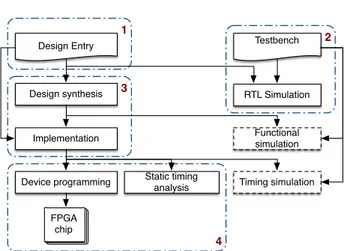
The FPGA circuits, in general term, are often designed using a HDL language (such as VHDL or Verilog) and configured by the vendor’s toolchain. Figure 1 shows the development flow of a FPGA HDL-based design [4]. The left portion represents the design and refinement process in which the design is transformed from an abstract HDL description to a device cell-logic configuration before being downloaded onto the chip. The right portion is the design verification pro-cess to check that the design is correct (RTL Simulation) and meets the functionality requirements (functional simulation) as well as the performance constraints (timing simulation).
The synthesis is known as the logic synthesis, in which the HDLs is transformed from the RTL constructs to generic gate level components. The implementation process consists of three smaller sub-processes : The translate process merges the designs to a single netlist. The map process maps the generic gates in the netlist to FPGA’s logic cells. Finally the place and route process defines the physical layout inside the FPGA and connects the logic blocks together. These two processes strictly depend on the vendor’s tool (Xilinx, Altera etc.).
B. Smalltalk as a hardware description an verification
language
As mentioned before, the lower steps (marked as 3 and 4 in figure 1) are strongly coupled to the vendor’s tools and
3 4 2 1 Design Entry Design synthesis Testbench RTL Simulation Functional simulation Timing simulation Static timing analysis FPGA chip Implementation Device programming
Figure 1: A HDL-based development flow: (1) Design the system and derive the HDL files. (2) Write the testbench and perform a RTL simulation to verify the design. (3) Synthesis and implement the design using the vendor’s toolchain. (4) Download the binary file (proprietary format) onto FPGA memory. The functional simulation and the timing simulation are optional and thus can be omitted from the development flow.
therefore are difficult to change. Our proposition is to model only the top level of the flow, concretely, the HDL design task and the RTL Simulation task (marked as 1 and 2). The main objective is to be able to use Smalltalk as a high-level hardware description and verification language; as well as to benefit from its integrated development environment to debug and manage the hardware designs.
The overall architecture of our methodology is shown in figure2. First we need to build an Hardware design abstrac-tion layer that acts as a abstracabstrac-tion layer between Smalltalk and VHDL. This layer models the basic principles of the VHDL, and thus can turn Smalltalk to a high-level hardware description language. It will handle all of ours Smalltalk-based design entries on the top.
From this abstraction layer, two lower modules will be developed : (1) one provides the Smalltalk-VHDL conversion ability which can help to generate an HDL-based design entry from the Smalltalk’s one. This module will create a path to the traditional design flow that brings our design to the real hardware via the vendor’s toolchain. (2) The other handles the RTL Simulation task where we can verify the correct-ness of our design right inside the Smalltalk environment. Note that, for the lower simulation levels such as functional simulation and timing simulation, we need the vendor’s tools consequently.
Since our purpose is to propose a simple and more efficient way to design the FPGA circuits, the methodology described above must meet some requirements below:
Correctness of conversion: The Smalltalk-to-VHDL
conversion must ensure the preservability of the algorithm. Moreover, since the synthesis and implementation are done automatically behind the scene, the produced VHDL must be a already-synthesizable VHDL without any further
modifica-Pharo
Smalltalk-based design entry
Hardware design abstraction layer
Smalltalk to VHDL RTL Simulation
HDL-based design entry
FPGA Vendor’s tools chain
Figure 2: A Smalltalk-based development flow: the modelling is done on top, at the language and simulation level and then provides a path to the vendor’s tools to make the design available on the real FPGA.
tion on it.
Reusability and Extensibility: The abstraction layer
must handle the compatibility of the Smalltalk-based de-sign with different FPGA devices and make it hardware-independent. This allows the reusability of the design without (or with a minimal) effort of modification. The design will also need to be extensible by subclassing, the more it is subclassed, the more its functionalities are enriched.
Simulation: As we only work at RTL level, the
simu-lation must allow the designer to verify the correctness of the design at that level. It’s ideal that the simulator can support the waveform by tracing the signal changes in a VCD (Value Change Dump) file. This kind of file can be viewed using an external viewer like GTKWave1, or much better, one
developed natively in Smalltalk [15], [16]. The possibility of using Unit test (SUnit) in the hardware design is also very appreciated.
Robust interaction with vendor’s tools: There are
different FPGA vendors out there (Xilinx, Altera, etc.), and every vendor has many FPGA families different (Xilinx: Vir-tex, Spartan, Artix, etc.). Therefore, in order to configure the design on any FPGA chip, we need to provide its hardware description to the vendor’s toolchain. The methodology must propose an efficient way to facilitate and automate this process [17], [18].
III. SOFTWARE PROGRAMMING ON FPGAs WITH
SMALLTALK
This section describes the approaches to communicate with the FPGA circuits from our Smalltalk-based robotic application.
A. Standalone FPGA
A standalone FPGA is a FPGA which can independently operate side by side with the host system. This FPGA has pre-configured circuits on it in order to perform a fixed algorithm
1http://gtkwave.sourceforge.net
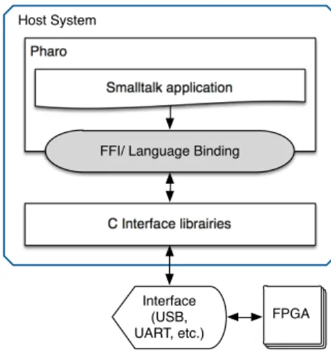
(image filter for example). Figure3 shows a typically com-munication flow between the Smalltalk-based software and the FPGA’s circuits via a common hardware interface like USB,RS232,etc. Here we use a Foreign Function Interface (FFI) such as NativeBoost[19], [20] to get access to the C librairies which define the interaction protocol with the FPGA circuits.
Although this approach is simple and easy to implement, it presents a potential risk of bottleneck when using these communication interfaces. In fact, the processing time on FPGA is fast, but the data transfer between the host system and the FPGA may be costly and therefore, can drop down the performance of the overall system.
Host System Pharo
Smalltalk application
FPGA C Interface librairies
FFI/ Language Binding
Interface (USB, UART, etc.)
Figure 3: A Smalltalk-based communication flow on a stan-dalone FPGA: the application on the host system interacts with the FPGA’s circuits via an interface of communication such as USB,RS232, parallel, etc.
B. Optimisation of software/hardware interaction with
FPGA-ARM SoM/SoC
A FPGA-ARM System on Module (SoM) or System on Chip (SoC) is an integrated circuit that integrates an ARM-based hard processor system (consisting of processor, periph-erals and memory interfaces) with a FPGA chip into a single module/chip. This integration brings Linux on top of the system as the software layer and makes the communication between FPGA and ARM more efficient while simplifying the development. Software application can talk to FPGA via its Extension Processing Platform Architecture [21] (usually provided by vendor) which allows us to interact directly with the FPGA registers. This will reduce the bottleneck problem. For this kind of FPGA-systems, we introduce a way to communicate with the FPGA by accessing to its registers. As shown in the figure 4, we host the Pharo Smalltalk on top of the embedded system (there is already a vir-tual machine for the ARM2 architecture), and then build a
Smalltalk abstraction layer to make our Smalltalk code talks to the FPGA registers via system librairies. At this point, the Register interaction abstraction layer provides a path to the
system librairies (Drivers/ Extension Processing Plateforme architecture) and brings their functionalities to the Smalltalk environment which opens a way to interact directly with FPGA registers from our Smalltalk application.
Linux Embedded System Pharo
Smalltalk application
Register interaction abstraction layer
FPGA Drivers / Extension Processing Platform
Architecture FFI/ Language Binding
ARM
Figure 4: A Smalltalk-based communication flow on a FPGA-ARM OMS/SoC : we use FFI (Native Boost for example) to access to system libraries in order to interact with FPGA circuits registers.
Note that, to program the system by this way, a pre-configured circuit is required to be available on the FPGA chip which provides the registers that our software want to interact with.
IV. EXPERIMENTAL VALIDATION
To make a proof of the challenges presented in sectionI, we first build a reference real-time robotic application fully in Pharo Smalltalk using an actual robot. By analysing this one, we would like to define the critical parts that have a negative impact on its performance. These parts will then be projected (designed) on FPGA to obtain a significant optimisation. Obviously, the transformed application will be evaluated quantitatively, and the expected result is that we’ll win an important gain in term of performance when using FPGA.
For the reference robotic application [22], we chose to develop a simple object tracking system (by color pattern) with a wheeled robot [23] available at Institut Mines-Telecom (as shown in figure5): the robot uses its camera to scan the whole environment and sends back an image stream. The application filters each received image by a color pattern using a HSV filter and looks for the target object (for example, a tennis ball). If the object is found, the laser sensor data will be collected from the robot to mesure the distance to the object. Based on these parameters, the application will command the robot to move (forward, backward, rotate, etc) such way that the robot maintains always a safe (constant) distance with
the object. The application has been entirely developed in Smalltalk with the help of PhaROS3, a Pharo package that
allows us to interact with the robot via the ROS4middleware
[24], [25].
Figure 5: The Robulab.
When testing with the camera resolution of 320x240 (32 bit image, lowest resolution), we found that the application took around 230 ms to completely process each image, meaning 4 images per second. This speed is obviously far away from a real time application which demand at least 15-20 images per second. This is the critical part that need to be accelerated through using FPGA.
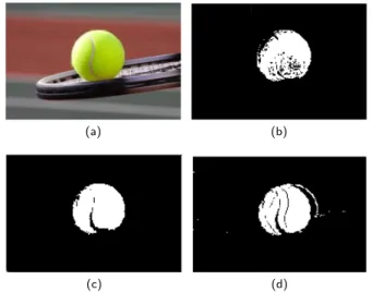
We are currently working on the projection of the image processing part on FPGA to obtain a hardware version of the algorithm. A first performance comparison between software and hardware implementation of the HSV filter [26], [27] has been performed. The algorithm gets a RGB image as input, transforms it to HSV color space and then filters it by a specific color pattern. We’ve implemented 3 versions of this algorithm using Pharo Smalltalk, C (with OpenCV) and FPGA circuits.
(a) (b)
(c) (d)
Figure 6: HSV filtre : (a) Original image; images filtered using Pharo (b), openCV (c) and FPGA circuits (d)
Figure6 shows the experimental results of these ones on an 192x128 image, 32 bit with the color pattern: 75 Æ H Æ
3http://car.mines-douai.fr/2014/02/pharos-fosdem-2014-slides/ 4Robot Operating System
150, 0.3 Æ S Æ 1.0, 0.5 Æ V Æ 1.0 (the tennis ball color range). Although there are a slightly difference between the filtered images, the object, in general term, is well identified in all case. On the processing performance side, we found that to completely filter the image, the Smalltalk, C, and FPGA implementation took around 73, 1.5 and 2.5 milliseconds respectively. That is, when passing from Smalltalk code to FPGA circuits, we obtain a very important gain (about 97%) in term of performance. However, the C implementation (with openCV) is shown faster than the FPGA one (around 1 millisecond) which seems surprising theoretically. In fact, in this experiment, we use a standalone FPGA and the image is transferred between the host system and the FPGA via an USB connection [28] for filtering. Here we encounter the bot-tleneck problem which drops down the circuits performance. With a FPGA-ARM SoC/SoM, this problem can be optimised and the FPGA implementation can perform more efficiently.
V. CONCLUSION
This paper presents the state of the art of an approach to use Smalltalk for software/hardware co-design on FP-GAs. In this work, we focus mainly on a general modelling methodology of hardware design at the behavioural (high abstraction) level that can make the hardware design task simpler and more efficient. We also propose a theoretical Smalltalk-based solution to communicate with the FPGA circuits (Standalone or SoC/SoM FPGA). We finally show a experimental comparison of performance between software and hardware implementation of a HSV filter algorithm which help us figure out some theoretical hypothesises.
References
[1] A. P. Black, D. Pollet, D. Cassou, and M. Denker, Pharo by Example. Square Bracket Associates, Switzerland, 2009. [2] A. Bergel, D. Cassou, S. Ducasse, and J. Laval, Deep into Pharo.
Square Bracket Associates, Switzerland, 2013.
[3] R. Robbins, “Advantages of FPGAs,” 2010. [On-line]. Available: http://www.controlengeurope.com/article/ 32043/Advantages-of-FPGAs.aspx
[4] P. P.Chu, FPGA Prototyping by VHDL examples (Xilinx Spartan-3 version). John Wiley & Sons, Inc., 2008.
[5] C. Cullinan, C. Wyant, T. Frattesi, and X. Huang, “Computing Performance Benchmarks among CPU , GPU , and FPGA,” WPI, 2012.
[6] Mike Field, “Introducing the Spartan 3E FPGA and VHDL,” 2012. [7] S. Vernalde, P. Schaumont, and I. Bolsens, “An object oriented programming approach for hardware design,” in VLSI ’99. Proceed-ings. IEEE Computer Society Workshop On, 1999, pp. 68–73. [8] T. Kuhn, T. Oppold, M. Winterholer, W. Rosenstiel, M. Edwards,
and Y. Kashai, “A framework for object oriented hardware specification, verification, and synthesis,” Proceedings of the 38th conference on Design automation - DAC ’01, pp. 413– 418, 2001. [Online]. Available: http://portal.acm.org/citation. cfm?doid=378239.378537
[9] M. Geilen, J. Voeten, P. van der Putten, L. van Bokhoven, and M. Stevens, “Object-oriented modelling and specification using SHE,” Computer Languages, vol. 27, no. 1-3, pp. 19–38, Apr. 2001. [Online]. Available: http://linkinghub.elsevier.com/retrieve/ pii/S0096055101000145
[10] J. Decaluwe, “Design hardware with Python.” [Online]. Available: http://www.myhdl.org/start/overview.html
[11] S. Swan, “An Introduction to System Level Modeling in SystemC 2 . 0,” Cadence Design Systems, Inc., Tech. Rep. May, 2001. [12] “SystemC.” [Online]. Available: http://systemc.org [13] Synopsys, “Functional specification for SystemC 2.0,” 2002.
[14] . Wikipedia english, “System on a chip.” [Online]. Available: http://en.wikipedia.org/wiki/System_on_a_chip
[15] D. Picard and L. Lagadec, “Multi-Level Simulation of Heteroge-neous Reconfigurable Platforms,” ReCoSoC’08, Barcelona, Spain, 2008.
[16] L. Lagadec and D. Picard, “Smalltalk debug lives in the matrix,” International Workshop on Smalltalk Technologies on - IWST ’10, pp. 11–16, 2010. [Online]. Available: http: //portal.acm.org/citation.cfm?doid=1942790.1942792
[17] S. Guelton, “Building Source-to-Source Compilers for Heteroge-neous Targets,” Ph.D. dissertation, Université européenne de Bre-tagne, 2011.
[18] E. M. Panainte, “The Molen compiler for
re-configurable architectures,” Ph.D. dissertation, Univer-sitatea Politehnica Bucuresti, 2007. [Online]. Avail-able: http://www.narcis.nl/publication/RecordID/oai:tudelft.nl: uuid:8150156e-e633-4319-8685-ccac7b083434
[19] L. Laffont, S. Ducasse, and I. Stasenko, “NativeBoost Recipes : The X11 Journey.”
[20] I. Stasenko, C. Bruni, S. Ducasse, and L. Fabresse, “Language-side Foreign Function Interfaces with NativeBoost,” in Proceedings of International Workshop on Smalltalk Technologies, 2013. [21] XilinX, “Zynq-7000 All Programmable Software Developers
Guide,” 2014.
[22] L. X. Sang, “Programming the Robulab to follow an object using color pattern,” Institut Mines-Telecom, Mines Douai/ ENSTA Bretagne, Tech. Rep., 2014.
[23] ROBOSOFT, “Robulab 10 user ’s manual,” 2008.
[24] A. Marin-Hernandez, “Robot Operation System,” RAP-LAAS-CNRS,DAI-Universidad Veracruzana, Tech. Rep., 2012.
[25] A. Martinez and E. Fernández, Learning ROS for robotics program-ming. Birmingham: Packt Publ., 2013.
[26] T. Hamachi, H. Tanabe, and A. Yamawaki, “Development of a Generic RGB to HSV Hardware,” The Proceedings of the 1st International Conference on Industrial Application Engineering 2013, pp. 169–173, Mar. 2013. [Online]. Available: https://www2.ia-engineers.org/conference/index.php/ iciae/iciae2013/paper/view/81
[27] B. M. Krishna, K. G. Deepika, B. R. Kanth, and V. G. S. Vemana, “Article: Image processing using ip core generator through fpga,” International Journal of Computer Applications, vol. 46, no. 24, pp. 48–52, May 2012, published by Foundation of Computer Science, New York, USA.
[28] M. Chris, “FPGALink User Manual,” 2012.
[29] W. Meeus, K. Van Beeck, T. Goedemé, J. Meel, and D. Stroobandt, “An overview of today’s high-level synthesis tools,” Design Automation for Embedded Systems, vol. 16, no. 3, pp. 31–51, Aug. 2012. [Online]. Available: http://link.springer.com/10.1007/s10617-012-9096-8