To link to this article : DOI:10.1103/PhysRevLett.108.054502
URL :
http://dx.doi.org/10.1103/PhysRevLett.108.054502
This is an author-deposited version published in:
http://oatao.univ-toulouse.fr/
Eprints ID: 9062
To cite this version:
Veran-Tissoires, Stéphanie and Marcoux, Manuel and Prat, Marc Discrete Salt
Crystallization at the Surface of a Porous Medium. (2012) Physical Review
Letters, vol. 108 (n° 5). 054502-p1-p4. ISSN 0031-9007
O
pen
A
rchive
T
oulouse
A
rchive
O
uverte (
OATAO
)
OATAO is an open access repository that collects the work of Toulouse researchers
and makes it freely available over the web where possible.
Any correspondence concerning this service should be sent to the repository administrator: [email protected]
Discrete Salt Crystallization at the Surface of a Porous Medium
S. Veran-Tissoires, M. Marcoux, and M. Prat*INPT, UPS, IMFT (Institut de Me´canique des Fluides de Toulouse), Universite´ de Toulouse, Avenue Camille Soula, F-31400 Toulouse, France
CNRS, IMFT, F-31400 Toulouse, France
Efflorescence refers to crystallized salt structures that form at the surface of a porous medium. The challenge is to understand why these structures do not form everywhere at the surface of the porous medium but at some specific locations and why there exists an exclusion distance around an efflorescence where no new efflorescence forms. These are explained from a visualization experiment, pore-network simulations and a simple efflorescence growth model.
DOI:10.1103/PhysRevLett.108.054502
Salt crystallization is an important issue in building physics because of the severe damages caused by the crystallization process [1]. Salts can enter stone and ma-sonry by several routes, the simplest of which is the cap-illary rise of ground water. As the water wicks up into a wall, it also evaporates. When the evaporation front is within the porous medium, salt crystals will precipitate inside the porous medium if the solution becomes super-saturated; this is called subflorescence. When the liquid-vapor interface remains at the porous medium surface, supersaturation leads to precipitation at the surface or efflorescence. Although less damaging than subflores-cence, efflorescence is an important issue for the conser-vation of old paintings and frescoes and can be also a problem in soil physics [2] or in relation with the under-ground sequestration of CO2[3].
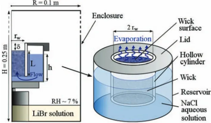
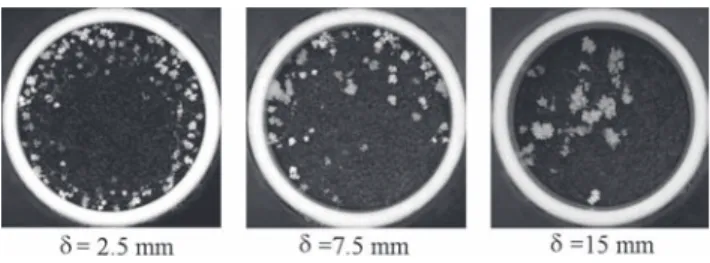
In order to develop a better understanding of efflores-cence formation, we performed the simple wicking experi-ment sketched and described in Fig. 1 [4]. Results are shown in Fig. 2. As can be seen, the localization of the efflorescence white spots varies with ! (! is the distance between the porous medium surface and the hollow cylin-der entrance in Fig.1). The other striking phenomenon is the discrete nature of efflorescence. Efflorescence does not cover the entire porous medium surface but forms individ-ual and isolated growing structures. Hence an important fraction of the surface remains free of efflorescence.
We now provide explanations to the observations, dis-cussing first what happens before the occurrence of the first crystal at the porous medium surface.
It is essential to note that the evaporation process in-duces a flow within the porous medium. Since the menisci stay at the sample surface (the medium remains saturated), the evaporation rate Jm from a meniscus is balanced by a
liquid flow rate qm(due to capillarity) toward the meniscus,
qm¼ Jm=&‘; (1)
where &‘is the liquid density.
As a result, there exists a velocity field u within the pore space with an average velocity $U directed toward the surface given by U ¼ J=A=&$ ‘=" where "ð# 0:36Þ is
the porous medium porosity (see caption in Fig.3for the definition of J and A). Owing to the existence of the velocity field, the ions are transported by advection to the evaporation surface. As a consequence a salt peak builds up and salt concentration gradients develop. But as soon as a concentration gradient develops diffusion tends to level off the accumulation. Hence there is a competition between advection, which transports ions to the top of the sample and thereby causes accumulation, and diffusion. Using the initial concentration C0, the wick height L and $U
FIG. 1 (color online). Sketch of wicking-evaporation experi-ment. A pack of 1 mm glass beads (db# 1 mm) in a 50 mm long
hollow cylinder of radius rw¼ 19 mm forms a porous medium.
The packing of height L is in contact at its bottom with a NaCl near saturated aqueous solution (C ¼ C0¼ 25 g NaCl=100 g
solution; the saturation concentration is Csat¼ 26:4 g
NaCl=100 g solution). The liquid level h in the reservoir is at any time such that the wick remains fully saturated owing to capillary effects. The system is set in a cylindrical enclosure of controlled temperature (T # 22%C) and relative humidity (thanks to a LiBr saline solution, RH # 7%). The evaporation rate at the wick surface is varied by changing the distance ! between the wick surface and the hollow cylinder entrance.
as characteristic concentration, length and velocity, respec-tively, the dimensionless equation governing the dissolved salt transport within the pore space reads [5],
Pe !@C0 @t0 þ u $ U:rC 0"¼ 9C0; (2)
where C0¼ C=C0and t0 ¼ t=trefwith tref¼ L= $U; 9 is the
Laplacian operator and Pe is the Peclet number character-izing the competition between advection and diffusion
effects; Pe ¼ULD$
s (Ds¼ 1:3 ) 10
*9 m2=s is the diffusion
coefficient for the dissolved salt). For our experiment, this gives Pe # 2, 1.6 and 1.4 for ! ¼ 2:5, 7.5 and 15 mm, respectively.
As a result of the significant advection, the ion distribu-tion is characterized by a narrow region of high salt con-centration adjacent to the porous medium surface [6], whose size increases with time but remains narrow (on the order of 2–3 bead diameters). This explains why crys-tallization is observed at the surface and not inside the porous medium. Crystallization occurs when the saturation concentration Csat is reached (supersaturation effects are
negligible for NaCl [7]), and Csat is first reached at the
sample surface owing to the advection effect.
Efflorescence preferentially appears in regions where evaporation is the greatest (thus in the surface periphery when ! ¼ 2:5 mm) since the greater the evaporation flux, the greater the underlying velocities in this region as ex-pressed by Eq. (1). When ! ¼ 15 mm the evaporation flux is much more uniform at the surface (see Fig.3), and there is no peripheral preferential location of efflorescence spots anymore.
To explain now the discrete nature of efflorescence formation, it is essential to notice that the disordered nature of the random packing induces spatial fluctuations in the velocity field u within the pore space. The effect of this spatially random velocity field is illustrated solving nu-merically the transient transport problem represented by Eq. (2) using a 3D pore-network approach [8]. The porous medium is represented as a simple cubic network (of regular spacing db) of pores interconnected by tubes
(re-ferred to as bonds). The pore volumes and the bond radii are randomly distributed in the ranges ½0:3–0:426,d3b and ½0:09–0:21,db respectively, using Gaussian probability
density functions, in accordance with known data for ran-dom packings of monodisperse spherical beads [9].
The velocity and concentration fields in the network (initial concentration C0) are computed solving problems
equivalent to resistance network problems [4]. An uniform pressure is imposed at the interface between the network and the bottom reservoir. The imposed flow rate in each surface bond (bond in contact with the top surface of network) is given by Eq. (1) and deduced from the data shown in Fig.3(Jmðr; !Þ ¼ jðr; !Þd2b). The concentration
C0 is imposed at the bottom of network. A salt zero flux
condition is imposed at the surface menisci (the salt cannot leave the liquid phase before the crystallization onset). As a result of network disorder, the average velocity in the bonds varies randomly. This randomness induces in turn spatial fluctuations in the salt concentration within the network and therefore at the network surface.
The numerical simulations reveal that the structure of the salt concentration field at the pore-network surface remains unchanged (except at the very beginning of this transient process). Hence the location of each local
FIG. 2. Efflorescence discrete structures (top view of wick surface). The white spots are efflorescence. The projected ver-tical surface area of the white spots onto the wick surface is about the same in the three images.
FIG. 3. Distribution of evaporation flux j at the porous me-dium surface. The reference flux jrefis equal to J=A where J is the evaporation rate and A is the porous medium surface area: J ¼ 2:7 ) 10*8kg=s, 2:37 ) 10*8kg=s and 2:02 ) 10*8kg=s
for ! ¼ 2:5, 7.5 and 15 mm, respectively. The evaporation rate is measured from weighing the set–up and also computed solving numerically the vapor transport equations in the enclosure with a finite element code [4,11]. A good agreement is found with the measurements provided that free convection effects are included in the computations. The flux distributions are deduced from the numerical computations. The crucial point is that the evaporation flux distribution at the surface varies with !. When ! is small enough (! ¼ 2:5 mm), the evaporation flux is significantly higher at the periphery (somewhat similarly as in the classical coffee ring problem [5]) whereas for a sufficiently large ! (! ¼ 15 mm) the evaporation flux is much more uniform (jðr; !Þ # Jð!Þ=A) over the surface. One can refer to [11] for more details.
concentration extremum at the surface is always the same for a given realization of network and a given evaporation flux distribution. In others terms, the spatial distribution of the reduced concentration C-ðtÞ ¼ CðtÞ*CminðtÞ
CmaxðtÞ*CminðtÞat network
surface, where Cmaxand Cminare the surface maximum and
minimum concentration at time t, is independent of time t. The simulation results are presented in Fig.4, which shows an obvious correlation between the locations of concentra-tion maxima (which correspond to the places where crys-tallization must start) at wick surface and the distribution of crystallization spots in Fig.2. Thus the key role played by advection on the salt distribution in the pore space combined with the spatial fluctuations of the velocity field
in the porous medium explains both the peripheral local-ization (small !) and the discrete nature of efflorescence onset.
A puzzling question is why the efflorescence continues to grow forming isolated structures leaving surface pores between efflorescence structures free of efflorescence. To explain this phenomenon it is crucial to note that the salt structures forming efflorescence are porous [10]. Evaporation takes place at the outer surface of each struc-ture, which consequently pumps by capillarity the aqueous solution contained in the underlying porous material.
Hence, as sketched in Fig.5, the efflorescence structures first act as sinks at the porous surface (the dissolved salt is directed toward the efflorescence). The second effect is a screening effect, i.e., the fact that the evaporation flux becomes negligible in the porous surface regions located between the efflorescence structures. This can be illus-trated through a simple growth model in two-dimensions. The 60 ) 100 square cells computational domain corre-sponds to the rectangle bounded by a green thin dashed line in Fig. 5. Thus the underlying porous medium is not considered. In the gas region, we solve numerically the vapor concentration transport equation assuming a quasis-teady purely diffusive transport (9cv¼ 0) with the
bound-ary condition: cv ¼ 0 at y ¼ H, cv¼ 1 at y ¼ 0 (porous
medium surface) and at the efflorescence boundary (which
FIG. 4 (color online). Pore-network simulation of salt concen-tration maxima distribution at porous medium surface. The red dots correspond to the menisci where the reduced salt concen-tration C-is greater than 0.8.
FIG. 5 (color online). Efflorescence is porous and pumps by capillarity the liquid solution traveling in the underlying porous medium [10]. Efflorescence grows owing to the salt deposition occurring preferentially in efflorescence upper regions where evaporation is higher. As a result of efflorescence growth, evaporation from surface pores located between two efflores-cence structures is screened (the evaporation flux becomes negligible) and the crystallization concentration is not reached in these screened pores. By contrast, the liquid flow rate in a surface pore in contact with efflorescence increases. Compared to flow before the onset of crystallization, this induces a reor-ganization of the flow structure within the upper layer of porous medium, which explains why the efflorescence continues to grow forming discrete and isolated structures.
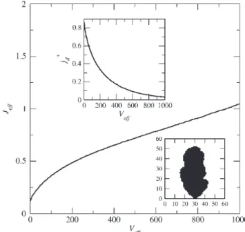
FIG. 6. Efflorescence pumping effect: evolution of evaporation rate Jeff from one efflorescence structure as a function of
structure size Veff (in number of cells). The screening effect is
illustrated in the inset top, which shows the evolution of dimen-sionless mean evaporation flux between two efflorescence struc-tures (along the thick dashed line in Fig. 5) as a function of structure size (the reference flux is the flux in the absence of efflorescence); an example of efflorescence computed shape is shown in the inset bottom.
initially is formed by two square cells located in the middle of the line y ¼ 0). Spatially periodic boundary conditions are imposed in the lateral direction. The ‘‘evaporation rate’’ at each edge forming the efflorescence contour is then computed (Jed¼ *rcv:n where n is the unit vector
outwardly normal to the considered edge). The efflores-cence grows locally proportionally to Jed. Some disorder is
introduced assuming that the porosity of each efflorescence cell varies randomly (details will be presented elsewhere). The results are summarized in Fig. 6 and illustrate the screening effect (top inset) and the local flow rate enhance-ment ( / Jeff) explaining the efflorescence discrete growth
(Fig.5).
In summary, the quantitative theory of efflorescence formation and growth is yet to come but we believe that the phenomenology described in this Letter opens up the route in this direction.
*Corresponding author. [email protected]
[1] G. W. Scherer,Cement and Concrete Research 34, 1613 (2004); O. Coussy,J. Mech. Phys. Solids 54, 1517 (2006); N. Shahidzadeh-Bonn et al., Phys. Rev. E 81, 066110 (2010).
[2] V. A. Kovda, Ambio 12, 91 (1983).
[3] Y. Peysson, M. Fleury, and V. Blasquez-Pascual,Transp. Porous Media 90, 1001 (2011).
[4] S. Veran-Tissoires, Ph.D. thesis, INPT, 2011.
[5] R. D. Deegan et al.,Nature (London) 389, 827 (1997). [6] Y. T. Puyate et al., Phys. Fluids 10, 566 (1998); H. P.
Huinink et al., Phys. Fluids 14, 1389 (2002); L. Guglielmini et al.,Phys. Fluids 20, 077101 (2008). [7] S. Chatterji, Cement and Concrete Research 30, 669
(2000).
[8] M. Prat,Chem. Eng. J. (Lausanne) 86, 153 (2002). [9] F. A. L. Dullien, Porous Media: Fluid Transport and Pore
Structure.(Academic Press, New York, 1992).
[10] N. Sghaier and M. Prat, Transp. Porous Media 80, 441 (2009).
[11] S. Veran-Tissoires et al., in Wicking in Porous Materials:
Traditional and Modern Modeling Approaches, edited by R. Masoodi and K. M. Pillai [Taylor and Francis, Boca Raton, (to be published)].