THESE
THESE
En vue de l'obtention du
DOCTORAT DE L’UNIVERSITÉ DE TOULOUSE
DOCTORAT DE L’UNIVERSITÉ DE TOULOUSE
Délivré par Institut National Polytechnique de Toulouse Discipline ou spécialité : Energétique et Transferts
JURY Pierre Sagaut Laurent-Emmanuel Brizzi Eric Lamballais Emmanuel Laroche Pierre Ginibre Laurence Vial Laurent Gicquel Tony Arts Rapporteur Rapporteur Examinateur Examinateur Invité Invité Directeur de thèse Codirecteur de thèse
Ecole doctorale : Mécanique, Energétique, Génie civil, Procédés Unité de recherche : CERFACS
Directeur de Thèse : Laurent Gicquel Co-Directeur de Thèse : Tony Arts
Encadrants industriels : Laurence Vial et Gontran Martineau Présentée et soutenue par Rémy Fransen
Le 13 Juin 2013
Cette thèse CIFRE a été rendue possible grâce à la collaboration bénéfique de l’en-treprise Safran Turbomeca avec le CERFACS et l’Institut von Karman, et je tiens à remercier chacun de ses membres qui y ont contribué.
Avant tout, je tiens à remercier sincèrement les membres du Jury qui ont accepté de lire et de juger mon travail. Merci donc à Laurent-Emmanuel Brizzi et Pierre Sa-gaut, qui m’ont fait part de leurs critiques, questions et remarques sur l’ensemble de mes travaux. Eric Lamballais, Emmanuel Laroche et Pierre Ginibre ont également participé à la discussion qui a contribué à élargir un peu plus ma vision et mes idées sur ces trois ans (et quelques) de thèse.
Au CERFACS, dans lequel j’ai passé la plus grande partie de mon temps du-rant ces trois ans, je ne peux d’abord penser qu’à mon directeur de thèse, Laurent Gicquel. Pendant une thèse on avance, on se trompe de chemin, on redémarre et de temps en temps on fait un grand bon en avant, autant sur le papier que dans la tête. A chaque fois je crois bien que tu y étais pour quelque chose, alors merci Laurent ! Un merci aussi aux différents seniors du CERFACS pour les discussions, en particulier Nicolas Gourdain, Florent Duchaine et Olivier Vermorel, conseillers respectifs informels en turbomachines, thermique et AVBP. Enfin, pour bien huiler l’ensemble, comment ne pas citer CSG pour le côté technique, une équipe efficace de support que j’aimerais pouvoir remmener avec moi, et pour le côté administratif, Chantal, Michelle, Marie et Nicole, qui mériteraient leur sigle aussi (le C2MN ?) pour leur bonne humeur et enthousiasme contagieux !
Mon passage au VKI m’a permis de rencontrer et de profiter de l’expérience de Tony Arts, avec qui j’ai pu approcher le monde expérimental dont mon clavier aurait pu avoir tendance à m’éloigner. . . Merci Tony, Filippo et les stagiaires de m’avoir montré comment assembler des vis, des lasers et de l’huile pour faire de belles images PIV !
Enfin, du côté de Turbomeca, un merci à Lonrenzo Pons et Laurence Vial sans qui cette thèse n’aurait jamais vu le jour. Grâce à vous j’ai pu me frotter au monde de l’entreprise à Bordes, où j’y ai rencontré d’autres collègues aussi compétents que chaleureux. Fred, Gontran, Yohan, Guilhem et tous les autres. . . Merci pour l’accueil et le bon esprit qui y régnait !
Je me dois également de remercier les responsables de l’ambiance qui règne au CERFACS. . . Au risque de m’attirer les représailles de la "communauté du café", je ne peux évidemment pas oublier les anciens, Pierre, Thomas, David, Pablo, P’tit Ju, et les "moins anciens" Abdula, Pierre, Laure, Thomas, ainsi que ceux de passage. . .
Merci pour toutes ces mémorables pauses où chocolats, fruits et autres touillettes ont subi la dure loi de la communauté. . . Parmi les thésards plus "pacifistes", je salue entre autres Greg, Basti, Geof et Mario compagnons de foot ou de sodexo nocturne. . . Elena, Anne et Élodie, merci de m’avoir laissé m’incruster à vos pauses gâteau, et Elena, re-merci pour ma nouvelle LV3 ! Ahora hablo un poco español tambien !
Les amis à l’extérieur, reconnaissables au fait qu’ils préfèrent voir des "ribs" dans leur assiette que tournant dans une turbine. . . Les ensmatiques et autres, épar-pillés en France et ailleurs, merci pour le soutien et désolé d’avoir eu droit aux tarifs étudiants 3 ans de plus. . . Merci aussi aux toulousains pour les moments de décom-pression, et en particulier aux ludiens jamais en manque d’énergie !
Enfin, ma famille Champardennaise, qui m’a laissé cette petite marque qui contraste beaucoup ici dans le sud-ouest lorsqu’on parle du ui-end. . . Merci de m’avoir soutenu et encouragé quand j’en avais besoin !
The aim of this thesis conducted for the Safran Turbomeca company was to study numerical cooling flows on both academical and real industrial configurations. To satisfy a non-disclosure agreement, several manuscript versions have been produced describing either both configurations or only the academic cases. The present ver-sion is the open verver-sion where all the industrial data have been removed. You may however note that some references still remain within the text (especially in introducing and concluding parts).
1 Introduction 1
Context . . . 1
Objectives . . . 4
Plan of the manuscript . . . 5
2 Turbine blade cooling: state-of-the-art and technology 7 2.1 Turbine cooling requirements . . . 7
2.2 Turbine cooling technology . . . 9
2.2.1 External cooling . . . 9
2.2.2 Internal cooling . . . 11
2.2.3 Cooling technology combination . . . 12
2.3 Ribbed Channels based internal cooling . . . 13
2.3.1 Ribbed channel controlling parameters . . . 13
2.3.2 Ribbed channels in rotation . . . 15
2.3.3 Realistic ribbed channels . . . 16
2.4 CFD of cooling channel . . . 16
2.4.1 Aerothermal computations . . . 17
2.4.2 Conjugate heat transfer . . . 19
2.5 Conclusions . . . 22
3 Internal cooling LES in non-rotating configurations 23 3.1 Internal cooling flow physics . . . 24
3.1.1 Non-dimensional approach . . . 24
3.1.2 General description of turbulent flows . . . 28
3.1.3 Turbulence Modeling . . . 31
3.1.4 Modeling cost . . . 33
3.2 Turbulent flows in a realistic cooling channels . . . 37
3.2.1 Smooth U-bend . . . 38
3.2.2 Ribbed channel . . . 39
3.2.3 Objectives of the following LES test . . . 42
3.3 LES numerical requirements for the VKI static cases . . . 43
3.3.1 U-bend computational domain . . . 43
3.3.2 Ribbed channel computational domain . . . 44
3.3.3 Periodic case numerical procedure . . . 45
3.3.4 Spatial case boundary conditions . . . 46
3.3.5 Domain discretization . . . 46
3.4 U-bend case . . . 47
3.4.1 Sensitivity to the upstream flow conditions . . . 48
3.4.2 Comparison with the state of the art . . . 49
3.5 Ribbed channel case . . . 52
3.5.1 Parametric analysis of the periodic LES . . . 52
3.5.2 Comparison with the industrial state of the art . . . 63
3.5.3 Spatial LES . . . 65
3.5.4 Heat transfer in the ribbed channel . . . 67
3.6 Conclusions . . . 71
4 Internal cooling LES in rotating configurations 73 4.1 Physics and modeling of rotating flows . . . 74
4.1.1 General transformation . . . 75
4.1.2 Governing equations in rotating frames . . . 76
4.1.3 Rotation and shear . . . 79
4.2 Simulation of rotating channels with AVBP: method and sensitivity 82 4.2.1 Modeling of rotating flows . . . 83
4.2.2 Numerical method in AVBP . . . 83
4.2.3 Validation test cases . . . 84
4.2.4 Conclusion . . . 86
4.3 Experimental rotating test bench . . . 86
4.4 Application of the rotating numerical methodology to the experimen-tal ribbed channel . . . 88
4.4.1 Domain and boundary conditions . . . 88
4.4.2 Expected flow topology . . . 89
4.4.3 Sensitivity analysis . . . 90
4.4.4 Results and interpretations . . . 90
4.4.5 Conclusion . . . 93
4.5 LES of the VKI isothermal rotating ribbed channel: validation against experiment . . . 93
4.5.1 Mean effects of rotation on the near wall flow topology . . . . 94
4.5.2 Effect of rotation on the flow field around the ribs . . . 98
4.5.3 Two-point correlations . . . 103
4.5.4 Temporal vortex tracking . . . 105
4.5.5 Conclusions on LES of rotating isothermal flows . . . 111
4.6 LES of the VKI anisothermal rotating ribbed channel: validation against experiment . . . 112
4.6.1 Mean temperature in the channel . . . 113
4.6.2 Flow field around the ribs . . . 115
4.6.3 Heat transfer at the ribbed wall . . . 116
4.6.4 Conclusions on the anisothermal study . . . 120
4.7 Conclusions on LES of rotating cooling channels . . . 120
Appendices 128
A RANS and LES modeling details 131
A.1 Physics and modeling of turbulent flows . . . 131 A.2 RANS . . . 133 A.3 LES . . . 134
B AVBP solver presentation 137
C Periodicity of compressible flow in a ribbed channel 139
D Comparison of LES simulations on full-tetra meshes with PIV
mea-surement 141
Bibliography 151
Latin characters
R Inertial frame of reference R∗ Non-inertial frame of reference
S Strain rate tensor . . . [s−1] f Body forces vector . . . [N/kg] Q Rotation matrix . . . [-] u Velocity vector . . . [m/s] Dh Hydraulic diameter . . . [m]
E Specific total energy . . . [J/kg] g Gravitational acceleration . . . [m/s2)]
h Ribs height . . . [m] hc Convective heat transfer coefficient . . . [W/(m2· K)]
hr Radiative heat transfer coefficient . . . [W/(m2· K)]
p Pressure . . . [Pa] q Heat flux . . . [W/m2] T Temperature . . . [K] t Time . . . [s] U Velocity magnitude . . . [m/s] u, v, w 3D velocity components . . . [m/s] uτ Wall friction velocity . . . [m/s]
x, y, z Space coordinates . . . [m] Greek characters
α Fluid thermal diffusivity
δij Kronecker delta . . . [-] λ Thermal conductivity . . . [W/(m · K)] µ Dynamic viscosity . . . [kg/(m · s)] ν Kinematic viscosity . . . [m2/s ] Ω Rotation rate . . . [s−1] ρ Density . . . [kg/m3]
τ Viscous stress tensor . . . [N/m2] Subscripts and superscripts
(−)′ Superscript for fluctuating quantities
(−)+ Superscript for quantities written in wall units (−)b Subscript for bulk quantities
(−)w Subscript for wall quantities (−)SGS, (−)t Modeled quantities (–)∗ Dimensionless quantities (–)i ith tensor or vector component (−) Reynolds averaged quantities
̃
(−) Resolved (Favre averaged or filtered) quantities Dimensionless numbers Bo Buoyancy number N u Nusselt number P r Prandtl number Re Reynolds number Ri Richardson number Ro Rotation number Acronyms 2D/3D Two/three dimensional CHT Conjugate Heat Transfer DNS Direct Numerical Simulation EF Enhancement Factor
LE Leading Edge
LES Large Eddy Simulation NS Navier Stokes
PIV Particle Image Velocimetry RANS Reynold Average Navier Stokes RSM Reynolds Stress Model
SGS Sub-Grid Scale TE Trailing Edge TI Turbulent Intensity TKE Turbulent Kinetic Energy
Introduction
Context
Aeronautical requirements
From the first mythical attempt to reach the sky with wings made of wax and feath-ers to our current world traveling cargo aircraft, human has always tried to improve his air mastery. In order to meet this dream, a long technical and innovative travel has been made to propel us further, faster and longer: from the highly trained ath-letic human able to provide up to 400 W [70] to the world record of thrust generation by the GE90 jet engine with 565 kN [47], and a power around 65 MW on a Boeing 777 at maximum cruise speed. Today this search for thrust and performance still continues: aircraft engine design has become the aim of a highly specialized industry which tries to increase engine power output while adapting its development cycle to current economic and environmental constraints: see for example recommendations from the European Economic and Social Committee on the European aeronautics industry [40] or the European aeronautical research program Clean Sky [21].
There are two main types of powerful engines with high power-to-weigth ratio. Depending on the type of application or work needed to drive the aircraft: i.e. pure thrust for turbojets or turbofans and torque for turboprops or turboshafts, two architectures are possible, Fig. 1.1. These two designs are composed of the same following main parts: an air intake, a compressor, a combustor, a turbine and a nozzle.
(a) Jet engine : CFM56 (b) Turboshaft : Safran Turbomeca Arriel Figure 1.1: Example of the two types of aeronautical gas turbine.
These parts are shown in Fig.1.2with the corresponding numbers: the air intake (1) is designed to provide an air mass flow at proper conditions for the compressor
(2) to increase the air pressure prior to the combustion. The compressor can be divided into several axial or centrifugal stages, driven by the turbine via a shaft running through the engine. The high pressure air is then mixed with fuel in the combustor (3) and burns to increase the gas mixture temperature. Finally, the hot gases expand in the nozzle guide vane and a part of the flow energy is extracted by the turbine stages (4) to power the compressor. In a turboshaft, most of the flow energy is converted into mechanical energy on a shaft in the subsequent turbine stages, whereas in a jet engine the hot gases are accelerated in a nozzle (5) to create thrust.
Figure 1.2: View of the different parts of an aeronautical engine (here a jet engine)
The working principle of these engine relies on the Brayton thermodynamic cycle presented in Fig.1.3. In an ideal cycle, compression of fresh air (1-2) and expansion of burnt hot gases (3-4) are assumed to be isentropic, while the combustion of the fuel-air mixture (2-3) and the gas exhaust to the atmosphere (4-1) are considered isobaric processes.
(a) (b)
Figure 1.3: Gas turbine working principle: simplified scheme (a) and ideal Brayton cycle (b)
Output power increase and improved efficiency of aeronautical engines can be obtained by increasing the pressure ratio in the compressor and by an increase of the turbine inlet temperature. This is confirmed by the performance map of Fig.1.4
extracted from Boyce’s handbook [10] for the simple gas turbine cycle of Fig.1.3a. Focusing on the turbine, a rise in temperature however imposes new constraints on the design of this component since the blade material melting point is already often well surpassed in existing modern gas turbine. The life duration of the turbine can therefore be greatly reduced if new protection systems are not developed to ensure the blade integrity over a reasonable time duration. The study and modeling of such systems, namely the air internal blade strategy is the point of interest of this thesis.
Figure 1.4: Performance map of a single cycle gas turbine [10]: efficiency and net output work are plotted against turbine inlet temperature (isolines) and compressor pressure ratio (measured values correspond to the symbols on isolines).
Internal cooling systems will be detailed in a next chapter, but an example of such a cooling design is presented in Fig. 1.5. The main principle relies on the extraction of a small portion of the compressor output fresh air. This air then by-passes the combustor and is reintroduced at the turbine stage where it flows inside the blades through especially designed cooling passages. Finally, the air is re-injected in the vein main flow through holes on the blade surface to create film cooling effect and protect it from hot burnt gases.
Computational tools
Emergence and evolution of computer science has developed fluid flow modeling eminently. First used in the 1930s to solve the two-dimensional linearized Navier-Stokes (NS) equations (Euler equations) for a flow around a cylinder by Thom [129], the so-called Computational Fluid Dynamics (CFD) numerical codes are now able to
Figure 1.5: Example of turbine blade cooling system with internal passages with turbulence promoters and holes on the surface for film cooling (image from Murata Lab. website, Tokyo University of A&T)
model three-dimensional full NS equations for complex industrial flows, like among many others, the case of interest of this thesis: flows in aeronautical gas turbines.
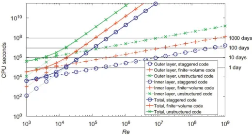
Today, three main methods are available to compute such industrial turbulent flows: Reynolds-Averaged-Navier-Stokes (RANS), Large Eddy Simulation (LES) and Direct Numerical Simulation (DNS) (see Pope’s description [102]). They are presented here in terms of increasing predictive capability, but also of increasing computational cost. Because of its low computational cost RANS remains the most frequently used CFD model by industry, while LES and DNS are essentially re-served to academic research. But thanks to the exponential development of the High Performance Computing (HPC), see Fig.1.6, LES becomes more affordable to the industry and its contributions on flow comprehension can be now assessed, as detailed by Tucker [132].
Objectives
In this specific framework of aeronautical demand for engine improvements and tremendous development of HPC abilities, Safran Turbomeca has launched several research and development projects [137,26] to analyze and quantify the impact of a wider use of LES modeling for engine flow predictions. Indeed, while LES has al-ready proved its potential for highly unsteady combustion flow computations in real gas turbine combustion chambers [85,123], its application to turbine flows is only beginning. This thesis focuses more specifically on the prediction and understanding of the aerothermal modeling of turbine blade internal cooling systems. The study is thus devised in multiple steps linked to the modeling and flow characteristics of such systems. These are summarized in the three following points:
1992 1994 1996 1998 2000 2002 2004 2006 2008 2010 2012Year 1010-1 0 101 102 103 104 105 106 107 108 109 Pe rfor ma nc e [G Flop /s]
#1
#500
Sum
Figure 1.6: Exponential performance development of the supercomputer top500 ranking [130].
• Characterization, validation and analysis of a numerical strategy to realize aerothermal LES of highly turbulent wall bounded rotating flows through the assessment of LES in simplified typical cooling channel configurations. • Application of this methodology to a realistic turbine blade cooling system in
engine operating conditions.
• Compare LES predictions of academical and industrial configurations with the regular tool used in the research department of Safran Turbomeca,i.e. the RANS modeling approach.
Organization of the manuscript
To achieve the previously defined objectives of this PhD dissertation, multiple sub-jects and developments have been investigated. This manuscript recapitulates these steps and is organized as follows:
• In Chapter 2, a state-of-the-art of turbine cooling systems is presented and
previous reference works on the typical configurations studied in this thesis are recalled.
• In Chapter3, physics of turbine blade cooling, fundamentals of fluid
mechan-ics and turbulence modeling are first recalled. Two stationary static flow con-figurations, a straight ribbed channel and a smooth U-bend, are then computed with LES. Descriptions, validations and comparisons with measurements and RANS results are proposed. LES numerical parameters such as mesh resolu-tion, cell topology or inflow specifications (turbulence injection) are evaluated. Detailed aerodynamical and thermal analyses of these unsteady predictions are finally performed.
• In Chapter 4, the ribbed channel is set in rotation: physics changes and the
corresponding modeling are presented and discussed. Results of clock-wise and anticlock-wise wall-normal rotating computations are detailed and a numerical sensitivity assessment is proposed. Note that a validation of these LES results is also provided thanks to measurements obtained on an experimental test bench using time resolved Particle Image Velocimetry (PIV). Change of heat transfer performances caused by the flow modifications are analyzed.
• In Chapter 5, not present in this manuscript version, the industrial cooling channel is investigated with LES based on the previous physical analy-sis and developed methodologies. Flow descriptions and conjugate heat trans-fer computations are given with comparison of predictions obtained with the Safran Turbomeca in-house tools.
• Finally, conclusions are drawn on the introduced methodology and on the assessment of the LES for internal cooling flow simulation. Perspectives are also proposed in the form of areas for improvement and further investigations.
Turbine blade cooling:
state-of-the-art and technology
Contents
2.1 Turbine cooling requirements . . . 7
2.2 Turbine cooling technology . . . 9
2.2.1 External cooling . . . 9
2.2.2 Internal cooling . . . 11
2.2.3 Cooling technology combination . . . 12
2.3 Ribbed Channels based internal cooling. . . 13
2.3.1 Ribbed channel controlling parameters . . . 13
2.3.2 Ribbed channels in rotation . . . 15
2.3.3 Realistic ribbed channels . . . 16
2.4 CFD of cooling channel . . . 16
2.4.1 Aerothermal computations. . . 17
2.4.2 Conjugate heat transfer . . . 19
2.5 Conclusions . . . 22
The introduction has pointed the interest and need of the industrial LES model-ing for turbine blade internal coolmodel-ing design and validation. To fully understand the possible issues raised in the introduction, it is necessary to understand the indus-trial requirements and what are the current technologies present today. Therefore, this chapter provides first an overview of the turbine cooling technology through its needs and the currently available answers. CFD modeling of such devices is then addressed giving the current state-of-the-art of internal cooling flow simulations as well as the Conjugate Heat Transfer (CHT) approach proposed today.
2.1
Turbine cooling requirements
As presented in the introduction, internal cooling of turbine blade has become an indispensable requirement for modern gas turbines to meet the increasing power demand, also synonym of higher gas temperature in the turbine which may surpass the material melting point. Cooling systems are already present in gas turbines for all static parts but its extension to rotating turbine blades is a task which has
Figure 2.1: Physical environment of a working turbine blade with major physical phenomenon.
to fit in the entire turbine design process in a more complex equilibrium than for the static parts. Figure 2.1 summaries the environment of a cooled turbine blade with high temperature coming from the combustor and the strong mechanical stress induced by the rotation. To guarantee the blade resistance to this medium, turbine blade internal cooling design is mandatory although a tricky process in which a compromise has to be found between multiple physical parameters. Figure 2.2
illustrates this problematic comparing the designer to a juggler who has to care about all the aforementioned constraints.
Figure 2.2: The technical "juggling" problem of the turbine blade cooling system designer [60].
The determining consequence of all this parametric choice is finally the blade life duration, and bad parameters may lead to premature failures. Table 2.1 describes the four main blade turbine failures and their temperature dependency following Ireland [60]. The result shows actually the influence of small metal temperature
differences on the blade lifetime which may be halved with some dozen degrees higher temperatures. However, Ireland also notes, using an uncertainty analysis, that the state-of-the art industrial tools is not able today to achieve the required accuracy for proper lifetime prediction (his computation leads to a temperature uncertainty of 35○C to 80○C). If prediction improvements are of great interest, Ireland also
concludes that internal heat transfer predictions would require an accuracy of about ±2%when current CFD solution typically reaches ±20%.
Table 2.1: Four main turbine blade failures and their temperature dependency [60].
Mechanism Metal temperature change todouble/halve life
Creep 15○C
Corrosion 20○
C
Low cycle fatigue 30○C
High cycle fatigue (vibrations) Not primarily temperature driven
2.2
Turbine cooling technology
The lack of blade metal temperature prediction accuracy pointed out in the pre-vious section has not prevented the blade technology development and a increased resistance to the always increasing turbine inlet temperature. Turbine blade im-provements have relied on two main strategies: enhancements in material charac-teristics and cooling systems. The former was the first to be developed, while the latter has appeared in the 1960’s [42]. Figure 2.3 presents the performance gain (linked to the turbine inlet temperature) evolution thanks to the combined use of both improved technologies. As already presented, the present study only focuses on cooling systems, but the reader interested in the mechanical aspects may look at other recent Safran Turbomeca modeling works by Ghighi [48]. Note also that Fig.2.3gives an idea of the potential room for improvement indicating the approxi-mative stoichiometric temperature of the fuel in comparison to the operating turbine inlet temperature.
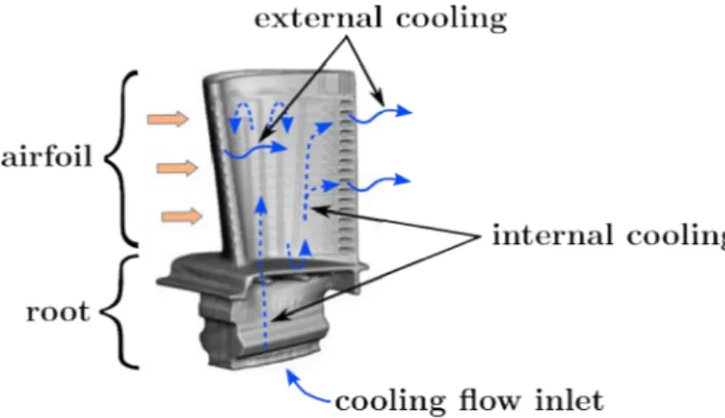
To describe now the different cooling systems available today on most engines, we consider the common blade construction pattern, Fig. 2.4. The starting point consists in a blade root with an inlet channel feeding the blade airfoil cooling sys-tem(s) with a relatively cold air extracted from the compressor. This cold air then flows through one or several cooling channels, to finally exhausts in the turbine main vein. Two types of cooling can be used depending on whether the coolant air flow interacts primarily with the external or internal faces of the blade.
Figure 2.3: History of the turbine inlet temperature [42].
Figure 2.4: Cooling flow in a turbine blade. Internal serpentine channels are visible by transparency.
2.2.1 External cooling
The aim of external cooling is the protection of the external blade surfaces exposed to hot combustion gases [54]. Two techniques may be used: film cooling and tran-spiration cooling, which is actually a generalized form of the former. Following the general description of Goldstein [50], film cooling is the introduction of a secondary fluid (coolant or injected fluid) at one or more discrete locations along a surface exposed to a high temperature environment to protect that surface not only in the immediate region of injection, but also in the downstream region. In the application, film cooling consists in ejecting cold air from the internal cooling system through small holes on the blade airfoil. Despite the principle simplicity, the technology faces a large amount of parameters which may depend for example on the flow properties, the injection geometry, the wall properties... Details on these effects can be found in Han [54].
As already pointed out, transpiration cooling may be considered as a generalized film cooling: instead of discrete cold air release locations, the entire blade walls (or only areas) releases cold air continuously through the surface. This can be made
possible thanks to naturally porous material, or using an in-wall small channel network, as presented for example in Fig.2.5. Transpiration offers a more uniform blade protection coverage than film cooling. It also yields additional cooling in the course of the fluid passing through the wall of the body thereby absorbing a part of its internal energy.
(a) Film cooling principle (b) Tansply Rolls-Royce system [60] Figure 2.5: External cooling example
2.2.2 Internal cooling
Internal cooling consists mainly in using convective heat transfer in internal channels to extract heat from the blade metallic wall to cool it down. To do so, more or less complex channels are hollowed out of the blade metal. Internal designs may therefore go from simple radial straight smooth channels extending from the hub to the tip, to long serpentine channels with turbulence promoters. A large panel of internal convective cooling systems has been developed since the first smooth channels in the 1960’s to improve heat exchanges. A list of the available designs may be the following: surface roughness, rib arrays, jet impingement, dimples, pin fins and swirl chambers (listed with corresponding references in Table 2.2).
The main principles on which these systems are based are the augmentation of exchange surface through flow turbulence increase. A lot of different arrangements are possible and they may be classified following the heat transfer increase in com-parison to a similar smooth channel without any cooling enhancement system. To be able to take into account any geometry, this parameter is commonly define as the ratio of the cooling system Nusselt number Nu to the smooth channel Nusselt number Nu0. As the main objective of blade cooling, heat transfer maximization
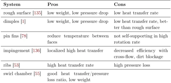
Table 2.2: Advantages and drawbacks of the common blade internal cooling systems
System Pros Cons
rough surface [135] low weight, low pressure drop low heat transfer rate dimples [1] low weight, low pressure drop low heat transfer rate,
bet-ter than rough surface pin fins [78] reduce temperature between
faces
not self-supporting in high rotation rate
impingement [136] localized high heat transfer decreased efficiency with cross-flow, dirt blockage
ribs [53] high heat transfer rate high pressure loss
swirl chamber [55] good heat transfer/pressure loss ratio, low weight
while minimizing the pressure drop penalties, the cooling systems may also be classi-fied following ratio comparing modiclassi-fied channel friction factors f to smooth channel friction factors f0. Very early on Webb [135] has for example proposed a parameter
to quantify the efficiency of roughness elements taking into account both pressure drop and heat transfer and know as thermal performance η:
η = N u/N u0
(f /f0)1/3 (2.1)
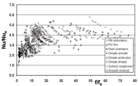
Figure2.6 proposed by Ligrani [83] presents the thermal performances showing the wide disparity between all the different cooling systems. A short review of the advantages and the drawbacks of each of solutions taken from [60, 83, 54] is also provided in Table2.2. Naturally the perfect cooling design offering the best thermal performance does not exist yet and blade designers have to adapt their choices following the specific engine characteristics and geometrical requirements.
2.2.3 Cooling technology combination
All the above internal and external cooling technologies are usually mixed together to improve the heat transfer efficiency. A lot of examples are available as patented arrangement. An actual example may be the blade of Kercher [68] using an internal serpentine smooth channel with transpiration stripes. One can also present the overall cooling effectiveness ϕ of a cooling system. By definition, this parameter is a dimensionless temperature ratio of gas-to-metal temperature difference over the gas-to-inlet-coolant temperature difference:
ϕ =Tgas−Tmetal
Figure 2.6: Comparison of relative performance of different internal cooling systems. Globally-averaged Nusselt number ratios are presented as in function of channel friction factor ratios [83].
with ϕ = 0 being the worst case when the metal has the same temperature as the hot gases, and ϕ = 1 the ideal case when the metal has the same temperature as the coolant. Figure 2.7 gives a summary in a graph by comparing some technological arrangements from the low efficiency radial convective internal cooling to the highly efficient transpiration cooling approach.
2.3
Ribbed Channels based internal cooling
In the application case of this thesis, only internal cooling is studied. Works of Collado [26] may provide more information on external heat transfer predictions. Focusing on the internal cooling system of the studied turbine blade shows that it has been designed mainly with ribbed cooling channels. There have been a lot of studies addressing the heat transfer performance of ribbed channels. This first subsection presents therefore a general description of the main influent heat transfer parameters for static cases, while the second extends it for rotating cases. For a complete review of this specific cooling system (among the others), Han [54] may be greatly recommended.
2.3.1 Ribbed channel controlling parameters
For heat transfer efficiency, Han [54] has identified major dependencies from the following three parameters of ribbed channels: the channel Aspect Ratio (AR, width to height ratio), the rib configuration and the flow Reynolds number Re. Mainly
Figure 2.7: Cooling effectiveness illustration for different modes of cooling [91].
geometrical parameters are detailed here, but flow dependency may be summarized by a slightly decreasing heat transfer with increasing Re (with 104 <Re < 105 for
typical applications).
The main physical phenomenon desired using ribs is the turbulence generation thanks to the creation of a separated flow. Figure 2.8 depicts this behavior with the commonly studied main features characterizing a rib arrangement: rib height e, pitch p and angle of attack α. Additional parameters are the rib cross-section (may be square, triangular, semicircular, trapezoidal; with sharp or round corners) and whether the ribs are continuous or broken for example. Concerning the channel where the ribs are placed, some parameters of importance are the cross section (often rectangular but may be triangular considering the blade leading edge cooling channel), the AR (square or rectangular with very flattened forms/shapes), the number of ribbed walls and the relative rib pattern along the wall (symmetric or staggered).
Among all these characteristics, the most commonly accepted for good heat transfer performance referring to a simple static channels is a rib height to channel hydraulic diameter ratio of around 0.1 and a pitch around 10. Angled ribs with α = 45○
∼ 60○ have also shown good heat transfer efficiency with relatively lower pressure losses if compared to α = 90○ ribs. Performance of the 60○ arrangement
may reach an averaged Nu/Nu0 up to 3 with a f/f0 ratio equal to 5 [97]
2.3.2 Ribbed channels in rotation
The study of rotor blade cooling introduces additional physical effects that need to be considered and in comparison to the stator blades for which previous observa-tions were more dedicated. The primary changes caused by rotation can significantly modify the coolant flow in internal channels. Rotating channel experimental obser-vations have been early obtained (see for example the work of Johnston [65] in 1972 on developed 2D rotating channel flow) and more recently with the study of
Figure 2.8: Schematic of flow separation from ribs and secondary flow between angled ribs in a rib-turbulated cooling channel [53].
Chang [18] in 2012 with 2D heat transfer detailed measurements in rotating ribbed channels. Following the nomenclature proposed by Wu [138] rotation will mostly refer in this document to a wall-normal rotation. Streamwise channel rotation will not be addressed here, while spanwise rotation may be similar to the wall-normal rotation considering finite AR channels. Therefore, in the considered rotation frame-work, non-inertial forces will redistribute the velocity, altering its fluctuations and generating streamwise large secondary flows. It results a channel flow with a sym-metry loss and the appearance of a destabilized side and a stabilized side, where turbulence levels is increased and decreased respectively. These effects depend on the rotation rate, which is characterized by the rotation number Ro: Ro = 0 for no rotation and increases with the rotation speed (further details are given in the next chapter).
Influence of the rotation induced forces may first be observed in smooth channels to understand how they affect the flow. Figure2.9ashows velocity profiles in rotating channels with radially outwards and inwards flows to be compared to a non rotating channels. First, Coriolis forces alone induce asymmetric velocity profiles depending on the radial flow direction. Then, buoyancy forces being always radially outward reinforce or damp the asymmetry when the flow has the same or opposite direction respectively. Figure 2.9b gives an example of the streamwise secondary flow which may be observed in a curved turbine blade and for which different channel orientation β with respect to the rotation axis appear. In this square cross section channel configuration, two counter rotating cells are detected with their center being aligned and parallel to the rotation axis. When β is modified, both vortices may not be heated by the same walls: in addition to one side wall, both leading and trailing walls for β = 0○ and either leading or trailing for β = 45○ for example. Such changes
may hence generate higher temperature differences when the walls are not uniformly heated [98].
All the cooling parameters presented for the static cases can be extended to the rotating context. In the specific case of ribbed channels and following the recent work of Coletti [24], rotation visibly alters the turbulence generation following the stabilized / destabilized principle. Moreover, the flow topology may also be strongly impacted by the buoyancy forces. The main effect is visible on a stabilized heated
(a) Conceptual view of effects of Coriolis and rotational buoyancy on radially outward and inwards flows [54]
(b) Schematic of cooling channel orientation in an airfoil [98]
Figure 2.9: Influence of rotation on turbine blade internal cooling channel flows.
ribbed wall where the recirculation bubbles generated behind the ribs can grow until taking all the space between two consecutive ribs. Since the core flow does not more reattach, heat transfer is reduced compared to the corresponding static case. One can also note that when buoyancy is further increased, heat transfer surprisingly re-increases, while the recirculation bubble thickness becomes larger than the rib height. An explanation for this phenomenon provided computationally by Sewall [116] will be detailed in the next section.
2.3.3 Realistic ribbed channels
The aforementioned works and the majority of the studies addressing ribbed chan-nels investigates simple geometries with often fully developed flow. However, in realistic turbine blades the cooling channels have to be adapted to the airfoil profile leading to non uniform channel shapes where the flow may never really reach a de-veloped state. A recent study by Leblanc [81] has presented detailed heat transfer measurements in a realistic cooling serpentine passage. It is shown that thermal correlations obtained in simple geometries over-predict the cooling performance in comparison to the experimental observations in the complex channel. This result provides insight into using correlations developed for simplified geometries and ide-alistic flow conditions to predict heat transfer for more reide-alistic geometries.
2.4
CFD of cooling channel
Convective heat transfer in channel flows has been widely studied and offers a large amount of theories and computation. In this section and following the focus of this chapter, we only address the presentation of turbine blade internal cooling results and more specifically ribbed channels. Aerothermal investigations are first presented comparing turbulence modeling and numerical approaches. Then, extensions to CHT computation are addressed.
2.4.1 Aerothermal computations
In industrial applications, RANS is the dominant form of turbulence modeling. Many industrial applications however evidence the limitation of the RANS approach, and DES as well as LES computations provide viable alternatives [28]. The two following subsections give examples of computations using RANS, LES and DNS along with the conclusions issued by these works.
RANS
RANS of cooling channels are numerous and some recent studies describe differ-ent behaviors depending on the RANS model. For eddy viscosity modeling, Ia-covides [58] concludes in his study of a ribbed channel with a U-bend that it is necessary to use low-Re closures for heat transfer. Ooi [95] compares three eddy viscosity models (k − ε, v2 − f, Spalart-Allmaras ) and finds that even if in a 2D ribbed channel v2 − f yields results in good agreement with experimental data, in a 3D case none of the tested models is able to predict the secondary flows leading to inaccurate heat transfer results (especially on the side walls). The same kind of conclusions is drawn by Phibel [99] for cooling channels with high blockage ra-tios. For modeling, the last authors point out the anisotropy assumption that is no more valid in ribbed channels and the unsteady nature of the large separated flow generated by the ribs.
Following these remarks, the use of more advanced RANS modeling like Reynolds Stress Model (RSM) [77] yields satisfactory results. Sleiti [117] performs a RANS computation with a RSM model providing good thermal predictions in a rotating two-pass ribbed channel with a U-bend. To capture the unsteadiness, one can note the work of Saha [111] who compares ribbed channels with different AR (1:4, 1:1, 4:1) in rotating cases using an unsteady RANS approach. He reports that AR has a strong influence on Coriolis induced secondary flows, leading to a high heat transfer difference between the trailing and the leading walls, while almost no significant difference in the 4:1 case. However neither experimental data nor more accurate modeling is available to assess his conclusions.
LES
As reported by Corson [28], the universality qualities of LES over RANS are becom-ing affordable thanks to the increasbecom-ing computational power. This has of course not prevented early cooling channel studies to be performed.
One of the first LES on a ribbed channel geometry was performed by Murata [92]. He investigated the heat transfer in a periodic ribbed channel and described several features as the high correlations between the wall shear stress and the wall heat transfer. Locations of the high heat transfer regions were also predicted by LES in good agreement with the measurements in the front of the rib and near the rib on the smooth side walls. He reported a dissimilarity between the velocity and the temperature field in the channel cross-section when the channel rotates.
The latter observation was also observed by Ahn [2] in a LES of a rotating ribbed channel with a similar geometry. Using vortex identification in the unsteady LES data, Ahn enlightened that the ribs created vortices inducing high wall-normal fluctuations and leading to heat transfer enhancement on the ribbed wall. In com-parison to a non-rotating channel, this heat transfer was increased and decreased on the trailing (destabilized) and leading (stabilized) ribbed wall respectively. Fig-ure 2.10 presents the time averaged Nu computed by Ahn compared to a similar (but not identical) experiment to describe this trend.
(a) (b)
Figure 2.10: Effect of the rotation on the time averaged Nusselt number between two ribs computed by LES on a destabilized (a) and a stabilized wall (b) of a ribbed channel [2]. LES (lines) are compared to measurements (symbols): − − − and square: Ro = 0; − · − and circle: Ro = 0.1; —: Ro = 0.3.
The same author also used LES to recently compare thermal efficiency of chan-nels with a more exotic rib configuration based on detached ribs [3]. Again, good agreement with experiment allowed Ahn to explore the 3D topology of the complex flow. He concluded finally in this case that detached ribs do not provide higher thermal performance than ribs on the wall due to higher pressure losses.
Cui [29] also relied on good LES validations against measurements to analyze different rib spacings. He showed that LES was able to predict correctly roughness
function at the wall and suggested the use of this approach to explore parametric variations in rib roughness.
If previous works addressed periodic flows, an interesting LES study on develop-ing flow is the investigations of Sewall [116]. He made a LES of a rotating straight cooling channel with 90○ribs and performed comparisons of Nu at different buoyancy
number (Bo). Sewall’s analysis gave an explanation for a particular evolution of the N uon a stabilized ribbed wall observed in several experiments. Namely, it has been observed that with increasing Bo, mean Nu first decreases (below Bo = 0.25) and then re-increases for higher Bo. Thanks to the LES, he proposed an explanation for this behavior as being due to the competition of first the growth of the sepa-rated flow behind the rib, and then an stronger entrainment of the fresh air in the core flow. The corresponding flow field and heat transfer results are presented in Fig.2.11.
(a) (b)
Figure 2.11: Recirculation bubble size between the ribs with increasing buoyancy (a) and corresponding Nu/Nu0 ratios (b) [116].
DNS
Finally, one can note several DNS confirming the experimental data and providing deeper flow comprehension. A DNS of a infinite AR channel provided with two ribs on a wall is performed by Labbé [73] with thermal analysis. Three dimensional vortical structures are highlighted and found to be responsible of increased heat transfer when they splash on the hot wall. The DNS of Nagano [93] investigates a finite-ratio channel with different transverse-rib roughness with varied spacing, width and height. It results that these parameters show signifiant influences on the heat transfer and pressure losses. Finally, one may mentioned the first DNS of a rotating channel by Kristoferssen [72] which issues numerous statistical data in a
wide range of rotation rates.
A non exhausting list of numerical studies performed on cooling channel con-figurations and addressed here are summarized in Table 2.4, while significations of abbreviation used to characterize them are given in Table. 2.3.
2.4.2 Conjugate heat transfer
In addition to the fundamental knowledge of the convective process in fluid flow, accurate heat transfer predictions in turbine blade cooling channel are basically also desired by the designers to estimate the blade lifetime. Toward this objective, cou-pled thermal computations between a fluid flow and a solid body also known as CHT computations have been already studied and used in the industry. But following the industrial state-of-the-art, CHT computations have been until now most widely per-formed with 1D networks or RANS modeling for the fluid part [104, 8,84,66]. In this way, the exchange methodology is simplified since only mean information are used. But looking at the advances in LES, it may be interesting to consider this tur-bulent flow modeling for CHT computations. This approach introducing unsteady computations with a wide frequency spectrum raises new coupling strategy ques-tions (computational cost optimization and numerical stability for instance [34]). Investigations of such issues have been the subject of several studies, as for example the works of Chatelain [20] and Jauré [63]. Chatelain has studied the tempera-ture fluctuations near the wall to propose the One Dimensional Variance Model (ODVM). This approach may be applied in the near wall region and reduce the LES computational time by transporting statistical information to the wall. Re-cently, Jauré [63] has more specifically performed a stability analysis studying the setup and the convergence of asynchronous fluid and solid coupled computations for massively parallel environments.
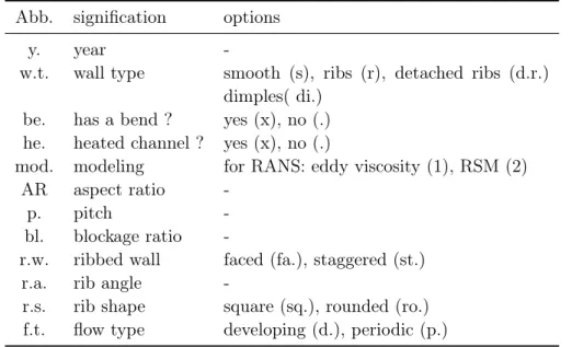
Table 2.3: Legend of abbreviations used to characterize the numerical studies pre-sented in Table2.4
Abb. signification options
y. year
-w.t. wall type smooth (s), ribs (r), detached ribs (d.r.) dimples( di.)
be. has a bend ? yes (x), no (.) he. heated channel ? yes (x), no (.)
mod. modeling for RANS: eddy viscosity (1), RSM (2)
AR aspect ratio
-p. pitch
-bl. blockage ratio
-r.w. ribbed wall faced (fa.), staggered (st.)
r.a. rib angle
-r.s. rib shape square (sq.), rounded (ro.) f.t. flow type developing (d.), periodic (p.)
Table 2.4: Description of some numerical studies of co oling channel. Significatio ns of abbreviation ar e giv en in Tab. 2.3 . Author y. w.t. be. R e [10 3 ] AR Ro he. p. bl. r.w. r.a. r.s. mo d. t.f. Iaco vides [ 58 ] 1999 r x 64 ∞ – x 10 0.1 2 st. 90 ○ sq. RANS (1,2) d. Jang [ 62 ] 2001 s,r . 25 1 0.0, 0.24 x 10 0.1 2 st . 45 ○ ro. RANS d. Al-Qah tani [ 4 ] 2002 s x 10 2:1 0 to 0.22 x – – – – – RANS Ooi [ 95 ] 2002 r . 30 1 – x 6,9,12 0.1 1, 2 fa. 90 ○ sq. RANS (1) p. Al-Qah tani [ 5 ] 2005 s . 10 4:1 0 to 0.28 x – – – – – RANS Sleiti [ 117 ] 2008 r x 25 1 0 to 1 x 10 0.1 2 st . 90 ○ ro. RANS (2) d. Saha [ 111 ] 2005 r . 25 0.25,1,4 0.12 to 0.5 x 10 0.1 2 st. 90 ○ sq. URANS (1) p. Murata [ 92 ] 2000 r . 4.1,9.2 1,4 1.0 x 10 0.1 2 fa. 90 ○ sq. LES p. Cui [ 29 ] 2003 r . 10 ∞ – . 1,4,9 0.1 1 90 ○ sq. LES p. Tafti [ 12 6 ] 2004 r . 20 1 – . 10 0.1 2 fa. 90 ○ sq. LES p. Qin [ 103 ] 2006 s . 4.5,5 ,10 1 0.01 to 0.09 . – – – – – LES p. Ahn [ 2 ] 2007 r . 30 ∞ 0.0 to 0.3 x 10 0.1 2 fa. 90 ○ sq. LES p. Sew all [ 116 ] 2008 r . 20 1 0.3 x 10 0.1 2 fa. 90 ○ sq. LES d. Ahn [ 3 ] 2010 d.r. . 30 ∞ – x 10 0.1 2 fa. 90 ○ sq. LES p. Elyy an [ 39 ] 2012 di. . 12.5 ∞ 0.0, 0.7 . – – – – – LES p. Kristoferssen [ 72 ] 1993 r . 25 0.25,1,4 0.12 to 0.5 x – – – – – DNS p. Nagano [ 93 ] 2004 r . 25 0.25,1,4 0.12 to 0.5 x 10 0.1 2 st. 90 ○ sq. DNS p.
2.5
Conclusions
A review of the state-of-the-art turbine blade cooling has been presented in this chapter. Addressing first the industrial requirements and the current technologies, second the CFD approaches for modeling the cooling systems, the following conclu-sions may be reported:
• The turbine blade cooling channel design is at the meeting point of several physical constraints requiring therefore to satisfy multiple criteria. In this scope, the blade metal temperature is the parameter of primary importance driving the blade lifetime. However, current industrial tools do not provide sufficient accuracy for this critical data. As a consequence, all areas require improvements, including CFD methods.
• Rib setups on channel walls are one of the most efficient turbulence promoter system. Numerous designs exist providing a large range of thermal perfor-mances which may also induce strong pressure penalties.
• Ribbed channels have been widely studied computationally with the common RANS and LES modeling. RANS with isotropy assumption is shown to be strongly dependent on the model used and leading to results with poor ac-curacy in 3D especially in regions where the flow is highly separated. More complex models such as RSM have shown satisfactory estimations for this specific issue. LES computations have proven a real gain over the RANS predictions in ribbed channels.
• Considering the methods for a potential industrial application, on can note that most of the LES studies have been performed on periodic structured meshes. Some of them have addressed developing channel flows but none have been found to investigate developing flow with unstructured meshes.
• CHT computations are well studied in RANS. The use of LES for CHT raises new issues due to unsteady flow solution which may cause physical data ex-change and stability problems [63].
Internal cooling LES in
non-rotating configurations
Contents
3.1 Internal cooling flow physics . . . 24
3.1.1 Non-dimensional approach. . . 24
3.1.2 General description of turbulent flows . . . 28
3.1.3 Turbulence Modeling . . . 31
3.1.4 Modeling cost . . . 33
3.2 Turbulent flows in a realistic cooling channels. . . 37
3.2.1 Smooth U-bend . . . 38
3.2.2 Ribbed channel . . . 39
3.2.3 Objectives of the following LES test . . . 42
3.3 LES numerical requirements for the VKI static cases . . . . 43
3.3.1 U-bend computational domain . . . 43
3.3.2 Ribbed channel computational domain . . . 44
3.3.3 Periodic case numerical procedure . . . 45
3.3.4 Spatial case boundary conditions . . . 46
3.3.5 Domain discretization. . . 46
3.4 U-bend case. . . 47
3.4.1 Sensitivity to the upstream flow conditions . . . 48
3.4.2 Comparison with the state of the art . . . 49
3.4.3 Conclusion on the U-bend analysis . . . 51
3.5 Ribbed channel case . . . 52
3.5.1 Parametric analysis of the periodic LES. . . 52
3.5.2 Comparison with the industrial state of the art . . . 63
3.5.3 Spatial LES. . . 65
3.5.4 Heat transfer in the ribbed channel . . . 67
3.6 Conclusions . . . 71
The great majority of the previous numerical studies has already yield a large amount of data for flows in academical cooling channel. To perform the desired computation of an industrial configuration, these results although of great value,
are however not applicable directly since not fully representative of a real cooling system. The objectives of this chapter are to present and evaluate preliminary numerical requirements and developments needed for LES of such flows which will be then used in the final application of this work.
The first section provides a non-dimensional analysis of the cooling channel issue in order to categorize all the physical phenomena at play. A general description of turbulent flows in an inertial reference frame, out of which static channel flow is a particular case is then provided. Physical and classical modeling approaches of such a flow are also presented at this occasion. Computational requirements for the particular case of wall bounded flows is detailed to propose alternative LES wall treatment based on a hybrid mesh. To focus on the concrete case of turbine blade cooling channels, the second section introduces two experimental academic cooling configurations drawn from industrial realistic channels. These experimental geometries for which preliminary tests will be detailed afterwards are a U-bend and a ribbed channel. The third section describes the different numerical domains of interest chosen for simulating the both experimental test channels with LES. The fourth and fifth sections present results of LES flow analysis in the U-bend and the ribbed channel respectively. In the bend, the sensitivity of the flow topology to the turbulent state is first investigated and validated with the experimental mea-surements. Then, the turbulence generation is directly addressed with the ribbed channel study. The latter examines the turbulent flow predicted by LES and assess the adaptation proposed based on hybrid meshes. In this scope, several meshes, wall treatments and LES model are tested. For both channel type analyzes, comparison of LES with RANS is also given to quantify the potential contribution of LES mod-eling for turbine cooling channel flows. Finally, the sixth section gives a summary of the results and conclude on the computational method recommendations.
3.1
Internal cooling flow physics
The internal cooling in turbine blades involves fluid dynamics and heat transfer in rotating systems. In this section, a non-dimensional analysis is first provided to describe all the physical phenomena at play and their respective importance. Then physics and modeling of turbulence, which link all of them in the present study, are introduced.
3.1.1 Non-dimensional approach
The combination of flow dynamics, thermal conduction and rotation may have dif-ferent relative influences on the flow behavior. Such effects can be quantified thanks to the use of classical dimensionless numbers.
Flow dynamics
The initial and preponderant physical mechanism used for internal blade cooling involves a fluid flow. To characterize such a flow, the common approach is to evaluate the ratio of inertial forces to viscous forces through the Reynolds number:
Re = DhUb
ν (3.1)
Dh is the hydraulic diameter of the channel, Ub the bulk velocity of the flow,
and ν is the kinematic viscosity of the fluid. A low value of Re characterizes a flow dominated by viscosity forces (laminar flow), while high values of Re give a flow with predominant inertial forces (turbulent flow). The choice of this flow regime has a strong influence on the fluid mixing, and therefore on the heat transfer.
Convective heat transfer
The desired main heat transfer mode in a cooling channel is the convective heat transfer. Convection characterizes heat transfer between a fluid and a surface or a solid. It is usually described by the Newton’s Law of Cooling which introduces the heat transfer coefficient h quantifying the proportionality between the wall heat flux qw and a temperature difference between Tw the wall temperature and Tref a
reference temperature to choose:
hc= qw
Tw−Tref (3.2)
Note that for convection dominated problems, the determination of a good ref-erence temperature to compute the convective heat transfer coefficient is an often raised problem [108]. But two other heat transfer modes exist and remain potential importance in our study: conductive and radiative heat transfer. The following paragraphs give methods to compare both of them against convection.
Convection and conduction The first heat transfer mode to be compared with convection is conduction. Conduction generates a heat flux qj which comes from
the Fourier’s law [59] involving the fluid thermal conductivity λ:
qj= −λ∂T ∂xj
(3.3)
For a problem involving a fluid/solid interface, one can consider that temperature and heat flux have to be equal at any time at the wall surface in the fluid and the solid. The convective coefficient h can hence be re-written with the Fourier law at the wall of normal n:
hc=
−λ (∂T ∂n)w
Equation (3.4) can then be non-dimensionalized, leading to Nusselt number Nu, which compares the relative importance between the convection and the conduction:
N u = Dhhc λf
(3.5)
Dh being the hydraulic diameter, λf the fluid thermal conductivity and h the
convective heat transfer coefficient. Note that Eq. (3.4) also shows that Nu repre-sents the dimensionless temperature gradient at the wall.
Convection and radiation Heat transfer through radiation takes place in the form of electromagnetic waves. Therefore, in our wall bounded flows, radiation due to hot walls can heat all the gas flowing in the channel. The hot wall emissivity and the fluid absorptivity need therefore to be evaluated to be compared to con-vection. To do so, a radiative heat transfer coefficient of the wall may be built and approximated with the following expression using the black body assumption [59]:
hr≈4σT3
Therefore, one can compare hr with the convective heat transfer coefficients hc to
evaluate their relative importance.
Heated fluid
Cooling issues involve necessarily a thermal changes in the fluid flow so that any fluid with a non uniform temperature distributions may be subjected to buoyancy effects. To evaluate the gravitational buoyancy influence on the fluid motion, one can use the Richardson number:
Ri = gDhβ(Tw−Tb) U2 b ≈g Dh U2 b Tw−Tb Tb (3.6)
where g is the gravitational acceleration and β ≈ 1/T is the thermal expansion coefficient. Ri quantifies therefore the importance of gravity in thermal flow studies.
Rotating fluid
Another characteristic of the flow inside a working turbine blade is that the fluid is subjected to rotation. Following the flow in the corresponding rotating frame of ref-erence may show an influence in comparison to the same non-rotating configuration because of the rotation induced inertial forces. The importance of one of them, the Coriolis force, is characterized by the rotation number:
Ro = ΩDh Ub
(3.7)
Rotating heated fluid
The second inertial force due to the rotation is the centrifugal force. This force may have the same influence as the gravity on fluids with a non-uniform temperature distribution. As a consequence and similarly to the Ri, the importance of rotation on such a flow is characterized by the Buoyancy number Bo, exchanging the gravity by the centrifugal force rΩ2 in the expression of Ri:
Bo = rΩ2Dh U2 b
Tw−Tb
Tb (3.8)
r is the mean radius of the rotating system. One can note that Bo/Ri = rΩ2/g showing that when the rotation increases, natural buoyancy becomes negligible in comparison to the rotating buoyancy.
Summary of the non-dimensional approach
All potential physical effects in turbine blade cooling channel flows have been in-troduced in the previous section. The appearance of the associated characteristic number for all cases addressed in this thesis is summarized in Table 3.1:
Table 3.1: Potential physical phenomenon in turbine blade cooling channel flows.
study case Re N u hr Ri Ro Bo
stationary & isothermal × – – – – –
stationary & heating × × × × – –
rotating & isothermal × – – – × –
rotating & heating × × × × × ×
First simplification assumptions
Gravity buoyancy It has been shown above that in a moderately to strongly rotating configurations, gravity buoyancy becomes negligible in comparison to the rotating buoyancy. Therefore, for the target rotating academic and industrial cases with a rotation rate of ∼ 10 rad/s and ∼ 1000 rad/s respectively, the gravity can be neglected. Note that in the intermediate non-rotating heated case, the temperature differences in the fluid will be low in comparison to the turbulent flow induced by the velocity addressed in this work. Gravity will therefore not be taken into account.
Radiation In view of the working temperatures of the academic and industrial configurations studied in this thesis, it can be expected that radiation may be neg-ligible in comparison to convection. A posteriori computed convective coefficients hc are compared to hr in Table 3.2confirming the hypothesis:
Table 3.2: Comparison of radiative and convective heat transfer coefficient orders of magnitude for the typical academic and industrial configurations.
study case hr hc
academical ∼10 ∼80/100
industrial ∼150 ∼1500/2000
The maximum radiative flux will therefore always be under 10% of the convective flux. Noting finally that the gas used in the cooling channels is always fresh air without highly absorbing molecules (such as H2O and CO2), one can reasonably
consider that radiative heat transfer can always be neglected in the framework of this thesis.
Conclusion of the non-dimensional analysis
Following the Table3.1and the above simplifications, the main physical effects that require to be taken into account in this thesis are turbulent flows, convective heat transfer, rotating flows and rotating buoyancy. This leads to the final Table 3.3
presenting the remaining main physical phenomenon of the cooling configurations studied in this thesis and the corresponding chapters where they are addressed.
Table 3.3: Dominant physical phenomenon in turbine blade cooling channel flows.
study case Re N u Ro Bo Chapter
stationary & isothermal × – – – 3
stationary & heating × × – – 3
rotating & isothermal × – × – 4
rotating & heating × × × × 4
3.1.2 General description of turbulent flows
The previous discussion has suggested that convective heat transfer is the key mech-anism for blade cooling system. To increase its effects, turbulence is the best flow regime found, as presented in Fig. 3.1 where experimental data and conventional correlations show that Nu is strongly increased with increase of turbulent Re.
Figure3.2portrays two views of the turbulent flow regimes that one encounters in everyday life for both main fluids present on Earth, air and water. Already studied by Leonardo da Vinci in the sixteenth century [107], and more recently characterized by Osborne Reynolds in the end of the nineteenth century [105,61], turbulence still keeps today a part of its secrets.
Before entering into a more mathematical and physical description of turbulence, one can describe how this phenomenon appears and identify the accepted underly-ing mechanism from the works of Reynolds [105] and Kolmogorov [69]. Using the
Figure 3.1: Nusselt number in pipe flows versus Reynolds number: example of Yang’s experiment [139] with conventional correlations.
previously presented dimensionless number introduced by the former, one can char-acterize a fluid flow state by measuring the ratio of inertial forces to viscous forces: that is the Reynolds number Re = UL/ν where U and L are respectively a charac-teristic velocity in m/s and length in m of the flow, while ν is the kinematic viscosity in m2/s of the fluid. Three main regimes are usually identified based on Re: the
laminar regime for low Re for which viscous forces dominate; the turbulent regime for high Re where inertial forces become the major contributors to the fluid motion; and in-between a narrow range of Re which is still today not fully mastered. The latter is usually qualified as the transitional regime where the laminar flow becomes intermittent before to become fully turbulent. In most aerothermal problems, like the one addressed in this thesis, the turbulent regime is of primary interest because its agitation creates more fluid mixing, which always enhances heat exchanges in air cooling systems, Fig3.1.
To describe the turbulent regime, Chassaing [19] proposes among others the following terms: random behavior, tri-dimensional geometry and non linear dynam-ics. These characteristics explain the difficulties in understanding and handling this common physical phenomenon. A proposition — because the issue is still an open problem — of definition is also given by the latter:
Turbulence is a natural mode of a viscous fluid flow where internal mechanisms of energy exchange carry out creation and conservation of continuously distributed chaotic motions hierarchy on a wide macroscopic scale range.
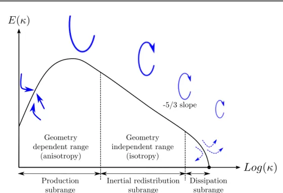
In the 1940s, Kolmogorov [69] proposed a mechanism to describe this contin-uously chaotic hierarchy and associated internal energy exchange, presented in a turbulent flow energy spectrum of Fig. 3.3. The spectrum shows the amount of energy carried by all the different scales in a turbulent flow. The largest structures,
(a) Sketch of Leonardo Da Vinci [107].
(b) Plume of smoke (Bohunice nuclear power plant, Slovakia)
Figure 3.2: Historical and modern observations of turbulent flows.
typically comparable in size to the characteristic length of the mean flow, bear most of the energy of the turbulent flow. In contrast the smallest scales, limited in size by the existence condition of Re = 1 where the flow becomes entirely viscous, con-tain low energy. The concept of an energy cascade between these scales has thus been introduced by Kolmogorov and assumes that the turbulent energy produced by the largest turbulent structures is transferred toward the smallest scales. The latter, also called Kolmogorov scale η = κ−1
η in Fig.3.3, finally dissipates flow kinetic
energy by viscous effects. This cascade is assumed to be the consequence of vortex stretching of intermediate eddies, with a −5/3 energy decrease characteristic law. In this theory, the major hypothesis which is the foundation of the different main flow modeling presented in the following section, concerns the separation between the large and the small scales. Whereas the former are always geometrically dependent and so always considered anistropic, the latter tend to become completely isotropic when the Reynolds number becomes high enough [19]. This assumption is at the root of the classification of the continuous range of turbulent motions in flows and is often applied in specific modeling concepts as detailed hereafter.
Governing equations
Instantaneous governing equations for a compressible Newtonian turbulent flow as studied in this thesis are written in Cartesian coordinates and using the Einstein notations (indices ranging over the set {1, 2, 3} for the three space coordinates):
∂
∂t(ρui) + ∂ ∂xj
Figure 3.3: Energy spectrum as a function of the wave number κ, and schematic energetic cascade (blue arrows)
In Eq3.9uiis the ith velocity component of the fluid, ρ its density, p the pressure,
τij the viscous stress tensor and fi the body forces. In order to fully describe fluid
flows, one must add to the previous equations the following conservation laws for mass, Eq.3.10, and energy, Eq.3.11:
∂ρ ∂t+ ∂ ∂xj (ρuj) =0 (3.10) ∂ ∂t(ρE) + ∂ ∂xj (ρujE + uipδij+qj−uiτij) =ρujfj (3.11) E is here the total energy per volume unit, which depends in addition to pressure on the viscous dissipation and the body forces already present in the momentum equations, as well as on the heat flux vector qj.
In the following, the entire set of these conservation equations will be called the Navier-Stokes (NS) equations and is the starting point of all the works presented in this document.
3.1.3 Turbulence Modeling
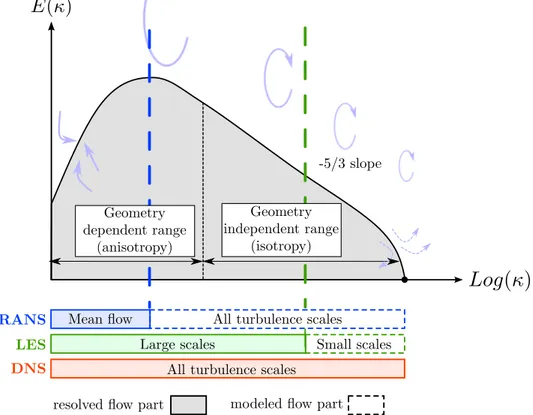
With the previous NS equations, we are now able to look into turbulence modeling to perform the computational resolution of a flows. In CFD, three main types of resolutions are present. These three methods, Direct Numerical Simulation (DNS), Large Eddy Simulation (LES) and Reynolds Averaged Navier Stokes (RANS), allow to solve the NS equations with different proportions of resolved / modeled fluid
scales and different associated computational costs. Figure 3.4 presents a scheme based on the energy spectrum and compares RANS, LES and DNS modeling, each method and its specifities being given in the following paragraphs and details in App. A.
Figure 3.4: Presentation of the three main methodologies to compute turbulent flows.
DNS
In DNS, a direct resolution of the NS equations is computed, which means that no turbulence modeling is needed. To resolve all the scales of turbulence, a very fine mesh is required since the spatial discretization needs to properly simulate the effect of the Kolmogorov dissipation scale on the spectrum evolution as well as the large scales of the flow. Considering that the ratio of the smallest turbulent eddies to the largest scales in a flow is inversely proportional to Re3/4, Pope [102] determines the
total computational requirement to perform a DNS of a 3D homogeneous isotropic turbulence. This results for the predictions of one large scale characteristic time into a number of floating point operations scaling as Re3.Since the objective of this
thesis is to evaluate available turbulence modeling in an industrial context with flow Reynolds number of the order from 105 to 107, DNS still and for a long time will
![Table 2.1: Four main turbine blade failures and their temperature dependency [60].](https://thumb-eu.123doks.com/thumbv2/123doknet/3563452.104392/20.892.199.708.385.526/table-main-turbine-blade-failures-temperature-dependency.webp)
![Figure 2.11: Recirculation bubble size between the ribs with increasing buoyancy (a) and corresponding Nu/Nu 0 ratios (b) [116].](https://thumb-eu.123doks.com/thumbv2/123doknet/3563452.104392/30.892.186.718.477.764/figure-recirculation-bubble-size-increasing-buoyancy-corresponding-ratios.webp)
![Figure 3.10: Experimental test bench from [16] used for validation of stationary numerical simulations](https://thumb-eu.123doks.com/thumbv2/123doknet/3563452.104392/53.892.177.699.535.709/figure-experimental-test-bench-validation-stationary-numerical-simulations.webp)