UML as a schema candidate for graph databases
V. DELFOSSE, R.BILLEN, P. LECLERCQ
University of Liège, Liège, Belgium
vincent.delfosse @ ulg.ac.be, rbillen @ ulg.ac.be, pierre.leclercq @ ulg.ac.be
Introduction
During the lifetime of a building, a huge quantity of information will be captured by multiple actors: owners, managers, users, architects, electricians, plumbers, etc. Because most of this information is not shared amongst these persons, the same analysis,
verifications or measurements have to be done multiple times. SpatioData is a research project aiming at the development of a collaborative platform to support the effective sharing of such diverse data.
In order to reach this ambitious goal, it is important to provide the users with devices suiting their needs (mobile or station) and interfaces adapted to their specific activities. These various client applications will communicate to a centralized database through web services exhibiting a common data model.
The data model of such an application has to address many problems. Among those: • The complexity of the data model to represent the different aspects of the
buildings, their actors, and the activities of these actors;
• The communicability, to ensure that developers willing to build client applications will understand and use the provided model in the same way; • The extensibility, to provide client-‐side developers with a mechanism to add
their own data schemes in the database;
• The flexibility, required in a research environment, where multiple questions are being co-‐resolved in parallel.
UML has been chosen for the representation of our data model, as it is a formalized and well-‐known format in the developers’ community.
But instead of fully developing the data model, then implementing it and providing dedicated services to it, an original approach has been adopted, in the form of UML-‐ oriented Web Services independent of any specific model. This solution has been built on top of a graph database (Neo4J) in a simple but powerful way, providing answers to the given problems above.
This paper details this solution and the process we have designed on top of it to make sure third-‐party developers can take full advantage of our platform.
Mapping UML to a graph database
Data modeling is arguably one of the most difficult tasks in the development process, especially when tackling complex domains. It can’t be done by I.T. specialists only, but instead, must implicate domain specialists. It takes the form of a multi-‐disciplinary dialog where IT specialists must learn enough of their interlocutor’s domain to propose models of it, to be validated or invalidated, in an iterative process.
When initially looking at the Neo4J technology, the first question we tried to answer was the mapping of a complex formalized data model into this new kind of database.
Surprisingly, we didn’t find any clear documentation for this necessary task. The tutorials that are provided seem to go against this idea, with each node having its own personal set of properties. After acquiring a better understanding of the technology, it became clear that graph databases were very flexible and able to support the many modeling formalisms. Still the tutorials introducing the technology were missing a clear and reassuring statement on schema mapping for curious developers coming from a ‘classical’ SQL background.
We have explored two ways of mapping UML to a graph-‐database, called “implicit” and “explicit” mappings. Each of them comes with its own set of advantages.
Implicit UML mapping
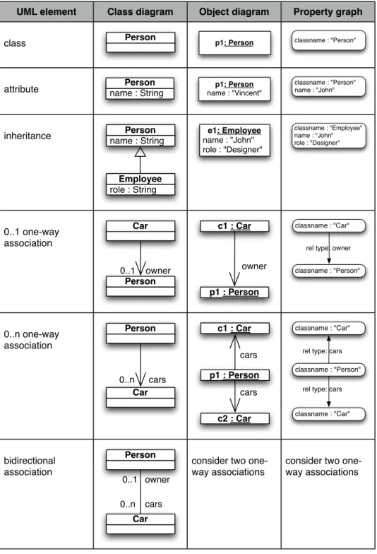
In the implicit mapping, the schema itself is not stored in the database. The objects to be stored are encoded in a systematic way derived from the UML class diagrams. It is the responsibility of the developers to comply to this mapping. Here is the mapping
implemented in our research project:
• An object of a given UML class is represented as a node with a specific reserved attribute ‘classname’ storing the class name as a string.
• Every UML attribute of a class is mapped to a node property. We are supporting a set of primitive types (string, int, double, date) all mapped to a string
representation in the database (numbers as human-‐readable strings and dates as the number of milliseconds since 01/01/1970, 00h00).
• A one-‐way association of cardinality 0..1 is mapped to a graph relationship. The type of the relationship is the UML role of the given association.
• Similarly, a one-‐way association of cardinality 0..n is mapped to a number of graph relationships. The type of these relationships is the UML role of the given association. We will distinguish between the two types of cardinality in the “UML API” section.
• Two-‐ways associations are represented as two one-‐way relationships. This is consistent with the way object-‐oriented languages like Java or C++ manipulates them.
• For inheritance in the class diagram, all the attributes and associations of the chain of parents are elements of the concrete objects and so are stored in the single graph node representing this object.
Figure 1 : mapping between UML class diagrams and property graphs
UML element Class diagram Object diagram Property graph
class Person p1: Person classname : "Person"
attribute name : StringPerson name : "Vincent"p1: Person classname : "Person"name : "John"
inheritance name : StringPerson
role : String Employee e1: Employee name : "John" role : "Designer" classname : "Employee" name : "John" role : "Designer" 0..1 one-way association Person Car 0..1 owner p1 : Person c1 : Car owner classname : "Car" classname : "Person" rel type: owner
0..n one-way association Person Car 0..n cars cars p1 : Person c2 : Car c1 : Car cars classname : "Person" classname : "Car" rel type: cars classname : "Car"
rel type: cars
bidirectional association Person Car 0..n cars 0..1 owner
consider two one-way associations
consider two one-way associations
Explicit UML mapping
In the explicit mapping, the schema itself is stored in the graph database. Every class is represented as a node describing its UML properties, associations and inheritance. This is useful for providing “refection” or “validation” functionalities over the data.
The objects mapping is the same than in the “implicit” mapping, except for the
“classname” properties, which now becomes an outgoing relationship of type ‘instanceof’ to the node describing the class of the object. To propose a mapping for the class
descriptions, let’s consider the simplified UML meta-‐model shown in the following Figure 2:
Figure 2 : Simplified metamodel of UML in UML
Being able to represent UML in UML itself is a powerful feature, allowing for a unified way of manipulating the models (classes) and the data (objects). We now have a system with three layers of abstractions, as shown in the following Figure 3:
In our system, we have two ways of generating the metamodel in the database: through a dedicated API (see next section), or by drawing the UML class diagram ina UML tool, then generating and processing the corresponding XMI file (XMI being an XML standard for representing UML documents).
In the implicit mapping section, we have shown how to manipulate objects (level M0) from a model schema (level M1). In the explicit mapping, we can access the class
description of an object (level M1) through the “instanceof” relationship, and manipulate it thanks to the meta-‐model of UML (level M2).
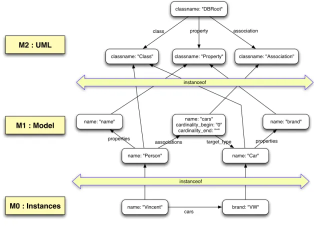
Figure 4 shows the complete database for the Person-‐Car schema and the two instances shown in Figure 3. All the relationships crossing an « instanceof » seperator is of type « instanceof ». The nodes are organized in 3 layers, matching the structure of Figure 3:
• M2 is composed of 4 static nodes : the root node of the database and 3 nodes representing the UML elements (class, property and association).
• M1 shows the model description for the Person-‐Car example. It is composed of 5 elements : the 2 classes, the association linking them and 2 of their properties. • M0 shows the graph representation of 2 objects, the association relating them
and the link to their class description.
Figure 4: Full database content for the Person-‐Car example of model and instances of Figure 3.
classname: "DBRoot"
classname: "Class" classname: "Property" classname: "Association"
name: "Person" name: "Car"
name: "name" name: "cars" name: "brand" cardinality_begin: "0"
cardinality_end: "*"
name: "Vincent" brand: "VW" properties properties
associations target_type
cars
class property association
instanceof instanceof
M0 : Instances M1 : Model
For querying the database, we rely on the Gremlin language (Gremlin). It enables us to follow the graph of UML objects with query expression derived from the class diagrams. We also made a slight syntactical rewriting of the Gremlin language, so that it matches the class diagram notation even more. This also prevents some code injection issues. Still, the main credit to our query system goes to the powerful Gremlin query language.
When considering the explicit schema representation into the database, it also adds querying capabilities based on class types, thanks to the queriable “instanceof” relationships linking objects to their class descriptions.
API on top of UML mapping
We now have a systematic way of mapping UML into a graph database. When the “object” view and the “graph” view are close to each other, it still would be more convenient for developers to consider the object view only. For instance, and for pure Java development only, there already exist an API based on Java annotations. See the “Frames” library from tinkerpop (Frames).
There are many motivations for providing an API on top of the UML mapping:
• An API encapsulates the mapping, and so provides a uniformed mapping for all developers.
• An API can add schema validation if needed.
• An API removes the database concerns from the developers, so that they only have to focus on the object-‐oriented side.
• An API can be ported to web services, in order to provide a distributed and language-‐agnostic UML store.
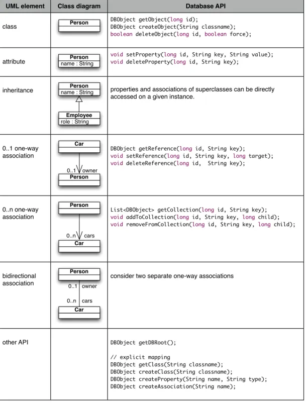
Our API has been implemented both in Java and as web services (Web Services). Figure 5 shows the proposed API in the Java form. A reference to an object in the database is represented as an id of type ‘long’. A DBObject is a structure with its id (long), its classname (String) and a collection of DBProperty. Currently, a DBProperty is just a key/value pair, both being strings.
Figure 5 : UML API for class diagrams Discussion
In the SpatioData project, we are currently using the “implicit” mapping described above. The combination of a graph-‐database with web services on top of our UML-‐oriented API leads to a very dynamic framework providing answers to the initial problems we are facing in SpatioData. It provides a distributed object-‐oriented database, with zero administration to be done once a client has decided upon his schema. Indeed, a client-‐ side developer just has to design and to draw his UML diagrams. He then has everything
UML element Class diagram Database API
class Person
DBObject getObject(long id);
DBObject createObject(String classname);
boolean deleteObject(long id, boolean force);
attribute name : StringPerson
void setProperty(long id, String key, String value);
void deleteProperty(long id, String key);
inheritance name : StringPerson
role : String
Employee
properties and associations of superclasses can be directly accessed on a given instance.
0..1 one-way association
Person Car
0..1 owner
DBObject getReference(long id, String key);
void setReference(long id, String key, long target);
void deleteReference(long id, String key);
0..n one-way association
Person
Car
0..n cars
List<DBObject> getCollection(long id, String key);
void addToCollection(long id, String key, long child);
void removeFromCollection(long id, String key, long child);
bidirectional association Person Car 0..n cars 0..1 owner
consider two separate one-way associations
other API DBObject getDBRoot();
// explicit mapping
DBObject getClass(String classname); DBObject createClass(String classname);
DBObject createProperty(String name, String type); DBObject createAssociation(String name);
he needs to create and manipulate his data directly. Basically, he draws it, he has it! If he wants his data to be known and used by a third-‐party application, he only has to communicate his schema to his partners to make this work. The only precaution he may want to take is to prefix his UML element names in order to avoid name-‐clashing with other UML elements in the database.
For the SpatioData project, this brings an interesting modeling process. The system provides a common “core” data model, acting like the central index or central common vocabulary for all the modules developed around this project. At the same time, they can easily extend this central model by adding their own schema on-‐the-‐fly. They can then communicate these model extensions to each other in order to share these extended data. Finally, if a model extension becomes mature enough so that it serves well a specific activity, it becomes a good candidate for being integrated in the official core. Somehow, we reach a sort of “standardization” process based on the pragmatic use of proposed model-‐extensions.
Acknowledgments
This article has been written in the context of the SpatioData project funded by the Walloon Region (WIST3 N° 1017094).
References Frames, https://github.com/tinkerpop/frames/wiki Gremlin, https://github.com/tinkerpop/gremlin/wiki Neo4J, http://neo4j.org/
OMG Unified Modeling Language (OMG UML), Infrastructure, OMG Document Number:
formal/2011-‐08-‐05, Standard document URL:
http://www.omg.org/spec/UML/2.4.1/Infrastructure
XMI, http://en.wikipedia.org/wiki/XML_Metadata_Interchange
Web Services, http://en.wikipedia.org/wiki/Web_service