ARGOS wavefront sensing :
from detection to correction
Gilles Orban de Xivry
a, M. Bonaglia
b, J. Borelli
c, L. Busoni
b, C. Connot
e, S. Esposito
b, W.
Gaessler
c, M. Kulas
c, T. Mazzoni
b, A. Puglisi
b, S. Rabien
a, J. Storm
d, J. Ziegleder
aa
Max-Planck-Institut f¨
ur extraterrestrische Physik, Garching, Germany
bOsservatorio Astrofisico di Arcetri, Firenze, Italy
c
Max-Planck-Institut f¨
ur Astronomie, Heidelberg, Germany
dLeibniz-Institut f¨
ur Astrophysik Potsdam, Postdam, Germany
e
Max-Planck-Institut f¨
ur Radioastronomie, Bonn, Germany
ABSTRACT
Argos is the ground-layer adaptive optics system for the Large Binocular Telescope. In order to perform its wide-field correction, Argos uses three laser guide stars which sample the atmospheric turbulence. To perform the correction, Argos has at disposal three different wavefront sensing measurements : its three laser guide stars, a NGS tip-tilt, and a third wavefront sensor. We present the wavefront sensing architecture and its individual components, in particular : the finalized Argos pnCCD camera detecting the 3 laser guide stars at 1kHz, high quantum efficiency and 4e− noise; the Argos tip-tilt sensor based on a quad-cell avalanche photo-diodes; and the Argos wavefront computer. Being in the middle of the commissioning, we present the first wavefront sensing configurations and operations performed at LBT, and discuss further improvements in the measurements of the 3 laser guide star slopes as detected by the pnCCD.
Keywords: Large Binocular Telescope, Ground Layer Adaptive Optics, Shack-Hartmann wavefront sensing, pnCCD, tip-tilt
1. INTRODUCTION
Argos is the Rayleigh laser guide stars and wavefront sensing facility at the LBT. Its prime driver is to be a “seeing enhancer” for Luci [1], the two near-infrared imagers and multi-object spectrographs, taking advantage of the LBT instrument and enhancing the FWHM by a factor 2-3 over the 40×40
Luci field of view. The key to success is to develop a reliable and robust system that greatly enhances the science “throughput” of the instrument by allowing faster observations and transforming good nights into excellent seeing conditions, whence demanding observing programmes could therefore be carried out most of the nights.
The Argos system is thus as follows : for each LBT eye, three Nd:YAG pulsed lasers form a constellation on a circle of 20 radius at 12km above the telescope. The backscattered light is directed in front of the Luci rotator stucture and a dichroic setup reflects the laser beams towards the Argos wavefront sensor system (WFS). The latter brings the beam closer together, stabilizes them, centers the pupil, and gates the light over an appropriate height of around 300m. The light then falls on a lenslet array forming three Shack-Hartmann (SH), with 15×15 subapertures each, on a single pnCCD detector. The sensor is then read at 1kHz, at which speeds it collects approximately 1500 photons per subaperture. In parallel, the 600-1000nm range is used for natural guide star tip-tilt and thruth sensing. The tip-tilt sensing will be performed by a quad-cell based on four Avalanche Photo-Diodes (APDs), while the truth sensing rely on the existing pyramid WFS. After collection of the different wavefront measurements, the Argos slope computer transmits the local wavefront gradients to the Adaptive Secondary Mirror (ASM) computer, reconstructing the wavefront and projecting it on the ASM actuators. Argos is currently in the middle of the commissioning process. The status of the project is reported in [2].
Further author information: (Send correspondence to G. Orban de Xivry) E-mail: [email protected]
In this contribution, we describe the wavefront sensing capabilities of Argos: its three LGS wavefront sensors, its NGS tiptilt, and the NGS wavefront sensing (FLAO, i.e. the First Light Adaptive Optics [3]) at LBT. The key element of this large amount of measurements is the Argos wavefront sensor computer that computes the LGS slopes, collects the tip-tilt and the FLAO measurements, and sends the full set of informations to the LBT ASM computer. We first present the Argos wavefront sensing architecture and its interfaces. We then take a closer look to the three wavefront sensing capabilities : the three LGS sensing, the NGS tip-tilt, and the NGS FLAO. We focus more specifically on the Argos wavefront sensor detector, the tip-tilt, and the capabilities of the Argos wavefront sensor computer itself. Finally, we present the first operations at LBT highlighting the flexibility of our wavefront sensing architecture, and discuss furture improvements in the centroiding computation with the Argos pnCCD.
2. ARGOS WAVEFRONT SENSING ARCHITECTURE
The LBT possesses an adaptive secondary mirror (ASM) by design. As such Argos does not need to implement a deformable mirror and its related wavefront reconstructor, but needs to take benefit of the existing facility.
Thus the central element of the Argos wavefront sensing architecture is its wavefront sensor computer. We sketch in Fig. 1 the nerve center of the Argos wavefront sensing, whose tasks are the following :
• It digitizes the analog signal from the Argos LGS wavefront sensor camera, described hereafter in sec-tion 3.1.
• It computes the x and y local wavefront gradients for three SH pupils, each containing about 176 subaper-tures, hence 1056 displacements.
• It does so at 1kHz based on pnCCD images of 264 × 264 pixels. This includes a custom data format and an appropriate data calibration.
• Minimum time delays in term of latency and jitter are ensured by this DSP-FPGA based computer, see below in section 3.4.
• As the nerve center of the Argos wavefront sensing, it provides the interfaces to the other wavefront measurements, in particular the NGS tip-tilt mandatory for the AO operation, and the measurements of a third WFS (from the natural guide star wavefront sensing unit or from a future possible Sodium laser guide star wavefront sensor). In addition it shall compute the LGS tip-tilt signals, to be corrected by piezo mirrors in the WFS optics.
• Finally, the computer must transmit the wavefront measurements to the LBT real time reconstructor and deformable mirror controller.
Argos has thus three different wavefront sensing measurements : its three LGS-GLAO, the needed NGS tip-tilt to cope with the laser sensing limitation, and possibly a third wavefront sensor, currently being the NGS pyramid FLAO. Those measurements are collected to form a final vector sf= [s3LGS, sTT, sFLAO], for a total of 1600 slopes measurements, and are sent to the ASM.
The ASM reconstructor converts the slopes into the mirror Karhunen-Lo`eve modal basis, using a propotional integrator. Once computed, the modes are then projected on the command space of the ASM by matrix multi-plication, which is then directly used by the internal control of the ASM. An additional disturbance vector can be added to this command vector, which is typically used for calibration.
The main elements to be calibrated from the Argos point of view is the reconstruction matrix to perform the mapping between the several wavefront measurements to the modal amplitudes. The matrix is obtained by pseudo-inversion of the interaction matrix. The latter is part of the calibration of the Argos AO loop and, crudely, is obtained as follows. Following a push-pull sequence, modes are successively applied to the ASM (i.e. by using the disturbance vector mentioned above) and for each of them the wavefront measurements are recorded thus constructing the matrix IM of dimension (Nslopes× Nmodes). The amplitudes of the push-pull of each modes is optimized to provide a uniform signal-to-noise by rescaling the applied amplitudes to have the same slope standard deviations.
Figure 1. Sketch of the Argos WFS computer. First, the computer receives the analog signal through 8 channels from the Argos pnCCD camera. It digitizes the data and send the pixel values to the DSP part of the board for LGS slope computation. In parallel, the computer can also receives the NGS tip-tilt slopes and the slopes from a third WFS (currently from the First Light AO (FLAO)). Finally, a slope vector is assembled and send to the LBT WFS switch, selecting the working wavefront sensor, and then the ASM control. We provide more details on the computer below in section 3.4.
The final Argos interaction matrix is assembled and essentially made of three blocks : the three LGS Shack-Hartmann sensors IMLGS;1−3, the natural tip-tilt sensor IMTT, and an optional third wavefront sensor IMNa/FLAOand can thus be written as follows,
IM = 0 0 IMLGS;1 0 0 IMLGS;2 0 0 IMLGS;3 IMTT 0 0 0 IMNa/FLAO 0 , (1)
This construction provides great flexibility on which wavefront sensor is used, as shown in section 4.
In addition to those wavefront measurements and the modal reconstruction, Argos will use the natural guide star wavefront sensing unit (FLAO) to measure slowly changing non-common path aberrations between the LGS optical beam and the near-infrared light going to Luci. This “truth sensing” will be projected back to the LGS slopes and offloaded as new offsets in the Argos wavefront sensing computer.
3. INSIDE VIEW ON DETECTION AND COMPUTATION
3.1 ARGOS LGS wavefront detection
Wavefront sensor system Coming from a 12km distance, the backscattered light from the laser beacons of Argos are picked up in front of the Luci instrument rotator structure by a dichroic setup and directed to the wavefront sensor optical system. Past the entrance window and the collimating lenses, periscope mirrors bring the light of the three laser beacons closer to the symmetry axis. The second mirrors of these periscopes, located at the pupil planes, are mounted on fast piezo tip-tilt stages. These fast tip-tilt mirrors stabilize the Shack-Hartmann patterns, removing the overall LGS tip-tilt as originating from residual laser beam jitter, and up and down propagation in the atmosphere. This is also controlled by the Argos wavefront computer, see
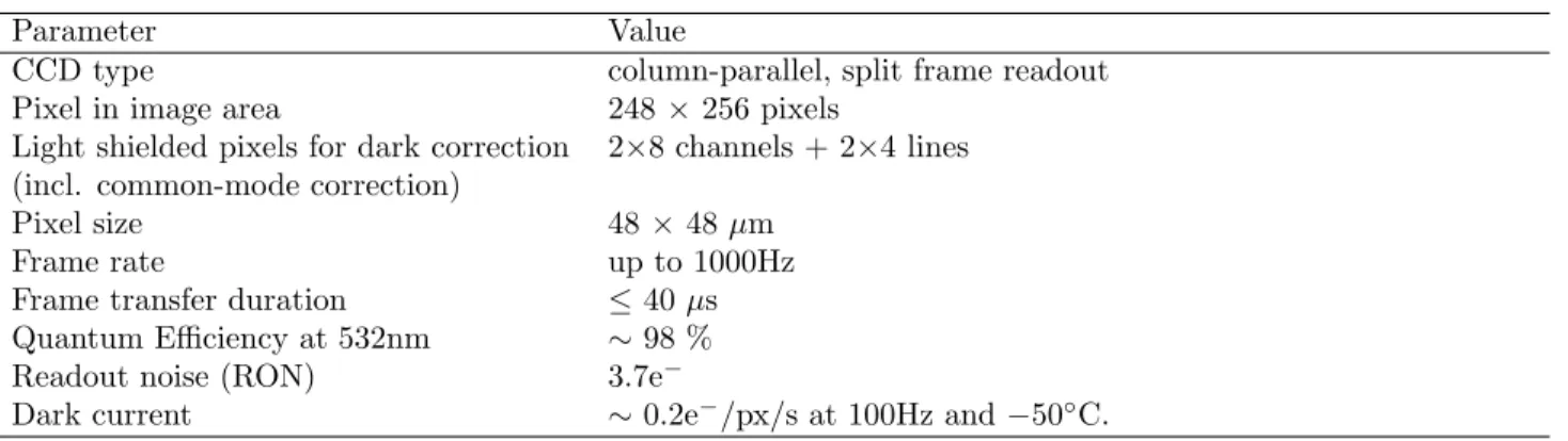
Table 1. Summary of the key pnCCD characterization.
Parameter Value
CCD type column-parallel, split frame readout Pixel in image area 248 × 256 pixels
Light shielded pixels for dark correction 2×8 channels + 2×4 lines (incl. common-mode correction)
Pixel size 48 × 48 µm
Frame rate up to 1000Hz
Frame transfer duration ≤ 40 µs Quantum Efficiency at 532nm ∼ 98 % Readout noise (RON) 3.7e−
Dark current ∼ 0.2e−/px/s at 100Hz and −50◦C.
Fig. 1. Following the periscope mirrors, optical shutters, based on Pockels cells, gate out the desired slice of the atmosphere from the backscattered light, i.e. a 300m range around 12km height. These Pockels cells are therefore synchronized with the laser pulses at ∼10kHz. Finally, re-focussing lenses, field lenses and a common collimator re-images the pupil onto a lenslet array in front of the Argos wavefront detector featuring a pnCCD, thus creating 3 Shack-Hartmann patterns on the pnCCD detector. Additionally, three cameras (called patrol cameras) are used to find the laser spots in their field of view of one arcminute in order to help the acquisition process. The optical gating, i.e. Pockels cell, is essential here to avoid dilution of the 12km guide stars by Rayleigh scattering throughout the laser propagation, or even low altitude faint clouds. Hence, the gating units are synchronized with each laser to the desired time duration, i.e. 2µs for a 300m slice of the atmosphere. This is a compromise between spot elongation and the number of collected photons, both influencing the accuracy of the wavefront gradient measurements. This system and its performances are described in detail in [4, 5].
The Argos wavefront sensor camera The end part being the detector, the camera simultaneously senses the three Shack-Hartmann patterns per LBT eye at 1kHz. Each Shack-Hartmann pattern provides about 175 subapertures leading to 350 slopes and allows Argos to correct for approximately 150 modes. In addition to this large number of subapertures, each of them is 8-by-8 pixels wide allowing large offsets of the spot positions. The pixel scale is 0.5600/px. Because the pnCCD is split in two half frames at the readout, and that those are treated separately at the computational level, the triangular symmetry of the on-sky beams had to be broken by the optical design. Hence, one of the Shack-Hartmann pattern is de-centered by 4 pixels on the pnCCD plane. Originally developed for X-ray detection by HLL/pnSensor, the pnCCD can be used for fast optical ap-plication. Indeed, the pnCCD features split frame transfer, frame store operation and column-parallel readout, and therefore it reaches frame rates up to 1kHz. The specificities of the chip are its combined high QE, low readout noise, excellent cosmetic, and high frame rate for a large image area. As such, it is suited for Argos and could be a technical solution for different AO applications [6]. The Argos pnCCD comes with newly developed camera housing, electronics, and control software, see also [6, 7]. Most recently, eight channel low-noise ADC have been developed and integrated to the Argos computer. The key specifications of the pnCCD, as used for Argos, are summarized in Tab. 1.
On the downside, this kind of parallel readout shows a line-to-line time dependent offset variation, i.e. the common-mode noise, as the detector is read out. To mitigate the impact on our wavefront sensing, we have used both hardware solution (new power supplies development) and software correction implementation in the Argos computer. We illustrate in Fig. 2 the effect of the common-mode before and after software correction on the standard deviation of the modes on open-loop data using one Shack-Hartmann pupil only. Where it increases the overall noises, it also injects some mode variations between approximately mode 15 and 35 of the LBT Karhunen-Lo`eve basis. The effect of residual common-mode has been previously studied through simulation showing a negligible effect [6]. However, we still observe a higher standard deviation in the x slopes versus the y slopes (see also Fig. 6. This can be mitigated by use of different centroiding algorithm, as we discuss below
100 101 102 103 mode number 100 101 102 st d d e v w f [n m ] high flux No common-mode correction Common-mode correction 0 20 40 60 80 100 120 140 160 mode number 0 .8 1 .0 1 .2 1 .4 1 .6 1 .8 2 .0 2 .2 2 .4 2 .6 st d d e v ra ti o w f
ratio – high flux
Figure 2. Open-loop data showing the standard deviation of the wavefront in nm versus the mode number. (Left) Log-log plot of the wavefront standard deviations with and without software common-mode correction. (Right) Ratio of the two standard deviation in linear space. The reconstructor was acquired at LBT. We can clearly see a noise shift and a bump between approximately mode 15 to 35 illustrating the effect on the wavefront.
in section 4. So far no effect has been observed on the first closed-loop data, and we will assess that in future commissioning runs.
At this stage, one Argos wavefront sensor detector is in operation at LBT. The second detector is in Europe for its integration and test of the LBT SX WFS system.
3.2 ARGOS Tip-Tilt sensor
The necessary NGS tilt wavefront sensor is a key element of Argos as the limiting magnitude of the NGS tip-tilt star directly drives the sky coverage and thus the science opportunities offered by Argos. In this perspective, a quad-cell APD-based tip-tilt tracker has been chosen. In this configuration, a 2 by 2 lenslet array is directly glued to optical fibers after a proper positioning adjustment for an optimum coupling. Those four fibers bring the light to four commercial APD units, i.e. four-channel Excelitas SPCM-AQ4C. This concept allows the lowest limiting magnitude down to R ∼ 18.5mag, as shown by early simulation (100mas or less jitter for a 18.5 R-mag star).
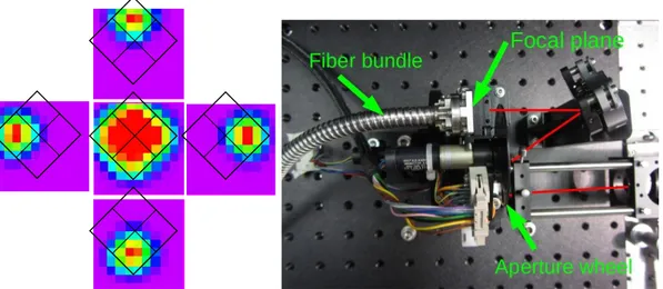
The lenslet array picks the light in the wavefront sensing board (w-board) of the Acquisition Guiding & Wavefront sensing unit in front of Luci. On the w-board, the light is reflected off a tilted beam splitter placed in the technical arm filter wheel. Right in front of the lenslet array, an aperture wheel allows for a trade-off between background level and seeing conditions. The APD sensors themselves are physically located in the wavefront sensing rack on the instrument platform and the light from the lenslet array is conveyed to the detectors with an ∼25m optical fiber bundle routed through the Luci derotator. The tip-tilt system is thus physically divided in two parts, namely the light pick-up system on the w-board system inside the AGW unit providing a ∼20×30patrol field, and the detector system in the WFS rack system. The light pick-up part, as integrated in our laboratory, is shown in Fig. 3.
The collected light from the natural star is in the range 600−870nm and, in the case of Argos, will be split as follows: 10% goes to the natural guide star wavefront sensor (i.e. pyramid WFS) to allow for slow “truth sensing” of low order modes to account for slowly changing non-common path aberrations and focus error, 90% goes to the technical arms. Of these, 95% is directed to the quad-cell for tip-tilt sensing and 5% to the technical camera to be able to quickly center the star on the quad-cell and to monitor the seeing and background conditions. The full FoV of the lenslet array is 2.300 but is adjustable with the aperture wheel, placed in front of the quad-cell. Thus, with this aperture the sky background can be lowered in good seeing conditions, maintaining an optimum response.
Apèrli
et.Figure 3. (Left) Response signal as a function of (x,y) position in a raster scan with step size of 0.2800. The outer four images represent the individual channel response, the central image being the sum. The black square contour represents the lenslet array layout. The spot size corresponds here to 0.900 on sky. Similar tests with an equivalent 0.2300 spot and smaller steps show that the sensitivity is very smooth over the array, with a minimal drop (∼25%) of sensitivity in the center. (Right) Light pick-up part of the Argos NGS tip-tilt sensor featuring a pick-off beam splitter and one mirror, a wheel with several apertures, and the lenslet array in the focal plane, the fiber bundle then direct the signal to the APD sensor in the wavefront sensor rack. Those optical parts will be placed on the w-board of the FLAO system.
After the APD sensors, a dedicated tip-tilt unit counts the APD TTL signals, corrects the data, performs the centroiding, and de-rotates the tip-tilt. The device consists of two components : a PC board running under linux hosting the control software and allowing remote control from the Argos software; a FPGA board counting and computing in real-time the tip-tilt. The unit can run up to 2kHz, and sends asynchronously the tip-tilt signal to the Argos wavefront computer. Effectively, it is limited by the Argos LGS WFS rate to maximum 1kHz.
One unit has been successfully assembled in Europe, and laboratory measurements show an overall photon detection efficiency to approximately 50% (which includes lenslet to fiber coupling, fiber transmission, and APD QE), as well as the good spatial response of the lenslet, as illustrated in Fig. 3.
3.3 A third wavefront sensor
In addition to its GLAO-LGS and tip-tilt sensor, Argos can benefit of the NGS pyramid WFS [3]. Argos can used those measurements in two different ways : as a truth sensor allowing us to update the slope offsets of the 3-LGS at a slow rates, or as high rate by sending data asynchronously to the Argos wavefront computer. The later allow us to use the pyramid WFS either as a tip-tilt sensor, while waiting for the more sensitive Argos APD unit to be ready, or in a hybrid mode using the three LGS to clean up the beam and sense fainter stars with the pyramid, see [8].
Alternatively, foreseeing for a future upgrade, a sodium line laser wavefront sensor could be readily interfaced pushing the system to diffraction limit over a large sky coverage.
3.4 The ARGOS wavefront sensor computer itself
The Argos wavefront computer is a custom device developed by Microgate, and is sketched in Fig. 1. The key elements of this integrated hardware are:
• a first board arbitrating the unit and providing the interfaces to the Argos supervisor (standard ethernet link), the tip-tilt unit (serial link), a third wavefront sensor and the LBT ASM switch BCU (both fiber link).
• a second board equipped with two ADSP-TS201 used for the high computational performances required by Argos. Each DSP processes half of the pnCCD. The board also includes the 16 bits analog to digital converter electronics performing the acquisition of the 8 channel analog inputs of the pnCCD.
...
...
...
...
...
...
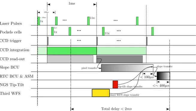
Figure 4. The full Argos sequence from laser pulse launch down to the deformable mirror control. As indicated, the NGS tip-tilt and the truth sensing/third WFS are asynchronous with respect to the 3LGS. The total delay between the wavefront measurement (taken at the middle of the exposure) and its correction is estimated to < 2ms.
• two high voltage controller boards used to drive three piezo tip-tilt mirrors in the Argos WFS to remove the LGS tip-tilt.
The three board are assembled in a mini-crate with one 16bits and one 32bits bus.
The ADC acquisition is controlled by the pnCCD sequencer at a 12.5MHz pixel clock. This also triggers the start of computation by the DSPs. It performs the data reduction (dark, flat, and common-mode corrections), and compute the centroid of the 525 spots. The algorithm for the centroiding allows the following computation [7] : center of gravity (CoG), thresholded CoG, normalized CoG, weighted weighted average pixels (WWPA, the flux is multiplied by its square-root), and weighted center of gravity.
The remaining task concerns essentially the handling of the interfaces with other devices :
1. The average LGS tip and tilt slopes are calculated to correct for field pointing error. This is an independent closed-loop that leads to the control of the already mentioned piezo-mirrors in the WFS.
2. The reception of the NGS tip-tilt from a serial interface, and of the measurement of a third WFS from an optical interface.
After those last operations, a final slope vector is created and sent to the wavefront reconstructor. Diagnostics are also available for download to the “Argos supervisor”. The wavefront computer can provide full rate slopes diagnostics and up to approximately 25Hz pnCCD frames, for live viewing and snapshot acquisition.
We sketch in Fig. 4 the full Argos timing sequence from the laser firing to the reconstruction done by the LBT ASM. The delay from end of exposure to mirror control is estimated to <1.5ms.
4. ARGOS WAVEFRONT SENSING FIRST OPERATION
The Argos WFS detector and the computer have been first successfully integrated to the WFS in Europe in spring 2013 and have undergone system test development in the following year [4, 5]. In March 2014, a first
Figure 5. Test images taken with Luci with short exposure (2.7seconds) of M13 with zoom insets. The FoV is 40×40
. (Left) Seeing limited image ∼0.900 with FeII filter (1.646 µm). (Right) NGS correction using the pyramid WFS on a central star, with the measurements routed to the Argos wavefront computer, and operating the ASM. This is done at 400Hz, 150 modes corrected. We obtain ∼0.300 in the center, ∼0.600 at the edges with the HeI filter (1.088µm).
wavefront sensor system has been installed on the LBT DX side. May 2014 has seen the first calibration and closed-loop test of Argos on a single guide star. The full status of the project is reported in [2]. Here we report the first wavefront sensing configuration used at LBT and discuss future improvements achievable with the centroiding algorithm.
First operations As a prior, communication between the wavefront computer and the LBT ASM switch had to be tested at the LBT, and subsequently debugged. The tip-tilt serial link and the FLAO fiber link to the wavefront computer have been tested at full frame rate (i.e. all at 1kHz). The amount of tip-tilt or FLAO frame skipped is small, maximum ∼2/100 frames.
Calibration has been done on individual LGS at 300Hz by applying push-pull disturbances onto the ASM, using the Argos calibration source and recording the computer diagnostics. From those individual interaction matrices, block-wise reconstructors could be built including the FLAO reconstructor.
The following operations have been realized :
• open-loop data acquisition and wavefront standard deviation computation, • closed-loop on the Argos individual calibration sources,
• closed-loop on the FLAO calibration source and open-loop data acquisition of wavefront rms on the LGS, • closed-loop on a NGS with the FLAO measurements being pipe through Argos,
• closed-loop on one laser guide star, optionally using the FLAO as a tip-tilt sensor.
Those different operational configurations have been very useful during our last commissioning run, e.g., to understand aberrations during calibration, and to cope with our currently missing tip-tilt unit.
Switching from configuration has also proven to be relatively easy where, as a by-product of our commissioning run, we have been able to acquire the first Luci test image corrected with the FLAO NGS. The correction performed was limited to 400Hz and 150 modes but showed significant improvement in the centre of the field and a slow decrease of the correction quality to the border, presumably indicating a strong contribution of the ground layer during that night, see Fig. 5.
CoG x slopes y slopes 0.000 0.005 0.010 0.015 0.020 0.025 0.030 0.035 0.040 0.045 0.050 rm s [p x ]
CoGN x slopes y slopes
0.000 0.005 0.010 0.015 0.020 0.025 0.030 0.035 0.040 0.045 0.050 rm s [p x ]
TCoGN x slopes y slopes
0.000 0.005 0.010 0.015 0.020 0.025 0.030 0.035 0.040 0.045 0.050 rm s [p x ]
WWPA x slopes y slopes
0.000 0.005 0.010 0.015 0.020 0.025 0.030 0.035 0.040 0.045 0.050 rm s [p x ]
Figure 6. x and y slope standard deviations for the 3 LGS on the pnCCD at low flux (∼200ph/subap/frame). We compare here four algorithms : CoG, normalized CoG (CoGN), thresholded normalized CoG (TCoGN, with a 1σ threshold), weighted weighted pixel average (WWPA) which weights each pixel flux by its square root. The normalization reduces the noise at the edge. The thresholding and WWPA improves the uniformity between x & y errors.
Slope errors So far Argos has been using a simple CoG for the slope computation. However several algorithms (see section 3.4) are implemented in the wavefront computer and can provide improvements in term of slope (or wavefront) standard deviation and uniformity of the errors, as we illustrate in the following.
In Fig. 6, we compute the x and y slopes standard deviation from data acquired using the WFS internal sources, and remap the result in 2D. We compare the CoG, normalized CoG, thresholded normalized CoG, and the weighted weighted pixel average (WWPA). From the CoG slope errors, one can observe two limitations : higher x slope errors as already mentioned in section 3.1, due to the common-mode correction; and higher noise at the edge of each SH pupil due to lower flux in those subapertures. We can see that the normalized algorithm decreases the noise at the edge, and, in effect, reduces the weight of those measurements. The thresholded and WWPA methods decrease the errors and the error non-uniformity between x and y.
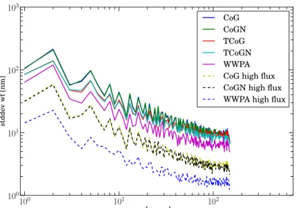
Finally, to get a sense of how much this could affect our wavefront error, we use the reconstructor acquired at LBT during our last commissioning campaign and compute the mode standard deviation of those open-loop data. A clear limitation of this approach is that the IM was acquired with the CoG algorithm only. However since this was acquired at high-flux, we assume that the response would be close to equivalent between the different algorithms, justifying at least qualitatively the approach presented here. In Fig. 7, we thus present the mode standard deviations for different algorithms computed at low flux (∼ 200ph/subap/ms), and high flux ∼1500ph/subap/ms).
We can make the following observations :
• Normalization seems to provide only marginal gain but is nevertheless expected to improve the loop sta-bility,
• TCoG and WWPA improve the uniformity in x and y slope noises (see Fig.3.) and thus reduce the noise propagation,
• WWPA would be the best both at high and low flux, but this need to be confirmed with a corresponding IM acquisition.
100 101 102 mode number 100 101 102 103 st d d e v w f [n m ] CoG CoGN TCoG TCoGN WWPA CoG high flux CoGN high flux WWPA high flux
Figure 7. Wavefront standard deviation in nm for the 150 modes of the K-L LBT basis. Full line are the low fluxes cases (∼200ph/subap/ms), dashed lines the high flux (∼1500ph/subap/ms). Improvements are clearly seen for the TCoG and WWPA. This result is however limited by the usage of a single IM acquired with the CoG algorithm (see also text).
5. SUMMARY
We have presented the general Argos wavefront sensing architecture. The wavefront computer and the pnCCD detector have been successfully put into operation on the LBT DX side. The first NGS tip-tilt sensor has been assembled and tested in Europe and will be installed at LBT in the next commissioning run. The flexible architecture has allowed first loop closure on one laser guide star, and NGS pyramid tip-tilt and wavefront corrections. The latter producing the first test image on Luci with AO correction. The slope computation of the 3 Shack-Hartmann on the pnCCD, and thus the wavefront rms, can be improved within the implemented algorithm. Furthermore, the architecture opens the door to future hybrid or tomographic correction schemes.
References
[1] Buschkamp, P. et al., “LUCI2: binocular and LGS/NGS AO modes of LUCI at LBT,” Proc. SPIE 9147(58) (2014).
[2] Rabien, S. et al., “Status of the ARGOS project,” Proc. SPIE 9148(46) (2014).
[3] Esposito, S. et al., “Natural guide star adaptive optics systems at LBT : FLAO commissioning and science operation status,” Proc. SPIE 8447 (2012).
[4] Busoni, L. et al., “Integration and laboratory characterization of the argos laser guide star wavefront sensors,” AO4ELT3 (2013).
[5] Bonaglia, M. et al., “Pre-shipment test of the ARGOS LGS wavefront sensor,” Proc. SPIE 9148(212) (2014). [6] Orban de Xivry, G. et al., “The ARGOS wavefront sensor pnCCD camera for an ELT: characteristics,
limitation and applications,” AO4ELT2 (2011).
[7] Orban de Xivry, G. et al., “Wide-field AO correction: the large wavefront sensor detector of ARGOS,” Proc. SPIE 7736 (2010).
[8] Bonaglia, M. et al., “Diffraction limited operation with ARGOS: an hybrid AO system,” Proc. SPIE 7736 (2010).