HAL Id: hal-01122245
https://hal.archives-ouvertes.fr/hal-01122245
Submitted on 3 Mar 2015HAL is a multi-disciplinary open access
archive for the deposit and dissemination of sci-entific research documents, whether they are pub-lished or not. The documents may come from teaching and research institutions in France or abroad, or from public or private research centers.
L’archive ouverte pluridisciplinaire HAL, est destinée au dépôt et à la diffusion de documents scientifiques de niveau recherche, publiés ou non, émanant des établissements d’enseignement et de recherche français ou étrangers, des laboratoires publics ou privés.
Human Body Perturbed Antenna Integration In Indoor
Propagation Simulator
Meriem Mhedhbi, Nicolas Amiot, Stéphane Avrillon, Bernard Uguen
To cite this version:
Meriem Mhedhbi, Nicolas Amiot, Stéphane Avrillon, Bernard Uguen. Human Body Perturbed An-tenna Integration In Indoor Propagation Simulator. Journées scientifiques 2014 de l’URSI France, Mar 2014, Paris, France. �hal-01122245�
URSI FRANCE2014: L´ HOMME CONNECTE´
Human Body Perturbed Antenna Integration
In Indoor Propagation Simulator
Meriem Mhedhbi*, Nicolas Amiot*, St´ephane Avrillon*, Bernard Uguen* *IETR, University of Rennes 1, France, [email protected]
Keywords
UWB antenna modeling, Spherical Harmonics, Physical Simulator, WBAN, Motion Capture, Radio Channel Simulation, Site specific modeling.
Abstract
This paper presents first results of simulation of a radio link between 2 antennas mounted on a the body. The body mobility is handled at two levels, the trajectory level and the body mobility level. A perturbed antenna model is used to acknowledge the effect of the body directly in the radiation pattern. Aggregated channel impulse response simulated in an Indoor environment is presented. The presented results validate the interest of the proposed approach for further integration with higher layer simulation.
Introduction
In the context of communication systems conception and design, the knowledge of the channel is always of importance. Especially, Body Area Networks (BAN) channels, since the trans-mission channel depends not only on the environment but it is also strongly affected by the body and its effect on body mounted antennas. In this work, for ease of the exposition, we
focus on a simple single agent, single link. However the presented tool has been designed to handle Body Area network (BAN) for multi-agent and multi-links situations. This require-ment being necessary for addressing the location related scenario defined in CORMORAN project : Large Scale Individual Motion Capture (LSIMC) and Coordinated Group Navigation (CGN) [1].
The BAN channel is manifold as it may consist of different kind of links : On-body and Off-body, the later including body to infrastructure and body to body links. The used simulator implements classical ray tracing techniques [2] and handles the agents mobility in a specific layout, as well as the body mobility using realistic body abstraction obtained from motion capture files. The antennas are fully described in a compact form using spherical harmonics expansions as described in [3].
The chosen approach has two levels. A first level acknowledges the motion of the center of gravity of the body along realistic indoor trajectories using a Discrete Event Simulator (DES) and a second level superimposes the body mobility on the trajectory. All the link of interest for the scenario can be calculated and stored for further post processing. To this end, a perturbed antenna model assessing the pattern behavior when antenna is placed around the human body is presented. This approach assumes that the effect of the body presence is being taken into account in the antenna radiation pattern, avoiding to manage a body description into the ray tracing. The paper is organized as follows: Section 1 describes human body mobility model, based on motion capture files, as well as the dedicated antenna model, Section 2 presents first integration simulations results and a comparison between situations using a body-perturbed and a non body-perturbed antenna.
1 Human Mobility and Antenna Model Integration
In this section, the Body Area Network channels simulation is presented including a descrip-tion of how are handled the human body mobility and the antenna model.
1.1 Modeling of Human Body Mobility
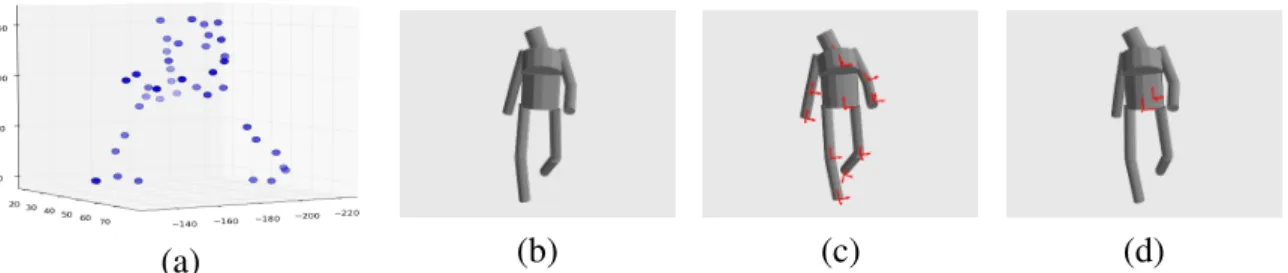
Different ways can be used to model the human body mobility. Traditionally, bio-mechanical models are used to represent the human mobility in a walking situation [4]. An alternative way is to make use of data coming from motion capture. Among the different existing motion capture data file formats, the C3D (Coordinates 3D) format is used here due to its compliance with most of motion capture systems. Among the data stored in C3D files are the whole 3D coordinates of a fixed number of points, representing human body sensors at very specific conventional location on the body at each time stamp. A 3D frame consists of a set of those 3D points. For example Figure 1.1 represents a 41 points’ frame. The main advantage of using motion capture data is that it enables to investigate a large variety of motion situations, not only limited to walking scenario.
The data extracted from C3D files are then used to build a human body cylindric model. The C3D data are filtered and a limited number of points is used 16 instead of 41 for creating
a simplified cylindric model. This model being a good trade off between fidelity of the repre-sentation and simplicity of the implementation. Similar approaches are proposed in [5]. The body trajectory is obtain from DES force based multi agent simulator which can produce an arbitrary number of realistic human trajectories into the Layout. Once the trajectory has been calculated, the body is inserted at the good location in time and space. Once properly posi-tioned it remains to handle the body mounted radiating element positioning and orientation in the global scene. This is done through the introduction of a chain of time dependent (except the global one) coordinates systems relating one to another via specific linear transformations (translation or rotation). The important aspect being to properly ponder the rays with the ap-propriate complex gain from the antenna pattern. The defined chain of coordinate systems is as followed:
GCS→ CCS(t) → DCS(t) → ACS(t) (1)
Where
• GCS refers to the global coordinates system. The Layout and the rays from the ray tracing are expressed in this GCS.
• CCS refers to Cylinder Coordinates System: each cylinder of the body model is asso-ciated with a dedicated CCS. A CCS is obtained from the large scale trajectory and the body frame corresponding to a given time on the body trajectory.
• DCS refers to Device Coordinates System : this CS is a rotated and/or translated version of the CCS. The origin of this coordinate system is the device position. A device is non ambiguously placed on a body cylinder via 3 parameters (l, h, cylId). 0 < l < 1 is a
parameterization of the length of the cylinder,his the height of the device w.r.t to the
cylinder of IdCylId.
• ACS refers to Antenna Coordinate System: it is an arbitrarily rotated version of the DCS that defines the antenna local coordinates system. The radiation pattern of the antenna is known in this ACS. One device could have theoretically several different ACS. This possible feature is not exploited in the following.
The Figure 1.1 shows the C3D frame (a), the body cylindric model built using C3D data (b), the body and all the CCS (c), and the body with the 2 selected DCS (d).
(a) (b) (c) (d)
1.2 Antenna Model
In the context of body area network radio channel simulation and modeling the knowledge of the antenna radiation pattern is fundamental. The human body disturbs in a considerable way the antenna pattern. One rigorous way to introduce the body effect in the physical sim-ulator would be to apply an electromagnetic solver. However, for the purpose of higher level simulation we are addressing, this approach is too computationally intensive. As a compro-mise alternative, we proposed to account for the body effect in the antenna pattern itself in using an equivalent antenna obtained from the unperturbed free space antenna and parameters depending mostly of the distance of the antenna from the body.
To study the effect of a human phantom on a UWB antenna a measurement campaign was carried out to study the effect of the human presence on antenna, where the antenna is mea-sured in free space and placed around a cylindric human phantom at different distances [6].
It is well known that a natural and compact representation of the antenna pattern is based on spherical harmonic (SH) basis expansion. According to [3],[7], the far-field radiation pattern
Fcan be expanded in terms of scalar spherical harmonics with vector coefficients: F (θ , φ , f , d) = L
∑
l=0 l∑
m=−l clm( f , d)Ylm(θ , φ ), (2)whereYlm(θ , φ )are the SH functions andclm are SH coefficients. Using spherical harmonics (SH) expansion the antenna data is reduced to few SH coefficients. Exploiting the above spherical harmonics decomposition we have proposed a model which predicts in the spherical harmonics coefficients domain the perturbation of the complex pattern caused by the human presence. It is obtained from experimental data and consists in a simple linear model relating SH coefficients of a disrupted antenna to free space coefficients and antenna-phantom distance:
˜
C(d) = A(d) Cfs (3)
Where d is the antenna-phantom distance, Cfs are SH coefficients of the antenna in free
space,C(d)˜ denotes the perturbed version of SH coefficients andA(d)is the linear model vector
of parameters representing the perturbation. The Figure 1.2 shows the ”Thomson” antenna patterns in the plane (x, y) at f = 4GHz in free space (green) and around the human phantom
(red) cases. We observe the perturbation brought out by the human phantom presence which is placed at the distanced= 30mmfrom the antenna. This model is described with more details
in [8]:
This model has been integrated in the indoor propagation simulator to simulate and model realistic BAN channel by taking into account the antenna perturbation.
2 Simulation and Results
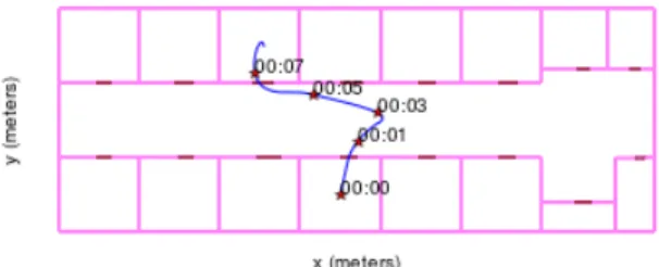
In this section, we consider the link hip to right wrist. Comparisons between using a perturbed antenna and a free space antenna are presented. The simulation is made in a defined layout and for a specific trajectory in a walking scenario shown in figure 2.1. There are 3 different regimes in this trajectory. The agent starts to move in a room, then goes into a long corridor,
0 30 60 90 120 150 180 210 240 300 330 -30 -25 -20 -15 -10 -5 0 5
free space antenna pertubed antenna
Figure 1.2: Perturbed (red) and free space (green) antenna pattern at f = 4GHz in the plane (x, y)
and finally reach an other room on the other side of the corridor. The overall trajectory time is
10sand the sampling period along the trajectory is10ms.
Figure 2.1:Simulation Layout and Agent 10 s trajectory from one room to another
At each instant the rays between the transmitter and the receiver are identified and evaluated. The antennas are applied with their proper orientation and the transmission channel impulse responseh(t, τ)is evaluated. The two pattern which has been used are presented in Figure 1.2.
The pattern used for the perturbed antenna is obtained using a phantom modeling of the antenna in the vicinity of a human arm. This same pattern has also been used for modeling of the antenna mounted on the hip which is of course less justified. However, for the purpose of the illustration of the approach this is not an issue. Any more realistic antenna pattern coming from a rigorous simulation or measurement could be used instead if more realism is needed.
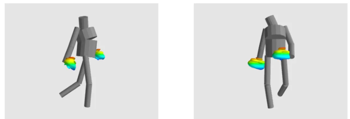
The Figure 2.2 represents the body cylindric model with antenna placed on the body. The chosen pattern radiates mostly toward the half space opposite to the body members (arms in this case). In fact, by using these antennas the human body presence is taken into account without requiring to actually represent the body in the global scene. Notice that this is an approximation which do not capture everything from the propagation phenomena appearing
on the body.
Figure 2.2: Body cylindric model with perturbed antenna
The channel impulse response is evaluated over a bandwith from 3GHz to 6GHz allowing UWB waveform simulation. The time varying channel impulse response is expressed as:
h(t, τ) =
K(t)
∑
k=0
αk(t)δ (τ − τk(t)) (4)
whereK(t)is the number of paths,αk(t)andτk are the amplitude and the arrival time of the
kith path.
The situation we are studying is an on-body channel, in the sense that transmitter and re-ceiver are placed on the body. However the part of the channel we are considering is obtained via off-body interactions. In this example the pure on body contribution is not fully taken into account especially in the delay domain. There exist a delay gap in the delay domain between the direct path and the first path coming to off body contribution (reflection on the environ-ment). In this section the preliminary results obtained for human body mobility and antenna model obtained with the WBAN physical simulator are presented as well as a comparison be-tween aggregated infinite bandwidth CIR obtained using a perturbed antenna and a free space antenna.
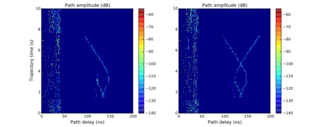
The Figure 2.3 shows the different paths amplitude and delays while the agent is traveling during the trajectory using free space antenna (right) and using a perturbed antenna (left). It shows the different regimes in the trajectory and how the channel structure varies with the environment. We notice that the global channel structure is nearly the same. However, we observe a dissimilarity in terms of paths amplitude since they are weighted differently according to the used antenna.
At the beginning of the trajectory during the 2 first seconds, the agent is walking in a small room the channel structure do not exceed50ns which corresponds to the vertical band on the
left. Then the agent goes out from the room, almost in the middle of the corridor, the two reflection at both end of the corridor are almost superimposed. Then the agent goes on the right until time 3s, then the delay from the reflection from corridor right wall is decreasing
while delay from the left wall is increasing. Finally, the agent reach another room and the multi-path structure observed during the first second is re-established.
The major effect of the body perturbed antenna is observed in to two specific region. The first one is the corridor region where the rays weights difference is clear and it illustrates well the body shadowing of one reflected path coming from the back. Thus, this simple approach is in fact able to capture correctly what would be observed in practice.
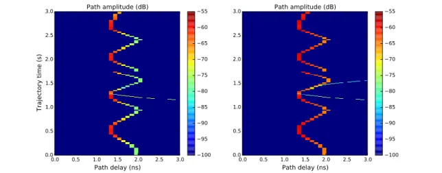
The second region and the most important difference is when zooming and observing the first paths affect by the body presence during 3s which corresponds to approximately to 3
human steps in Figure 2.4. It shows that the first paths amplitude do not vary in considerable manner when using the free space antenna. The observed variation is due to distance variation between the receiver and the transmitter, relative to the arm movement in a walking scenario, not the human body shadowing which is quite well reproduced with the perturbed antenna case where the line of sight, non line of sight and even the transition region are observed.
0 50 100 150 200 Path delay (ns) 0 2 4 6 8 10 Trajectory time (s) Path amplitude (dB) 140 130 120 110 100 90 80 70 60 0 50 100 150 200 Path delay (ns) 0 2 4 6 8 10 Path amplitude (dB) 140 130 120 110 100 90 80 70 60
Figure 2.3:Paths amplitude during trajectory time using perturbed antenna (left) and free space an-tenna (right).
This result might be well observed when representing the total received powerPr at each instant given by:
Pr(t) = K(t)
∑
k=0
|αk(t)|2 (5)
whereK(t)is the number of paths attandαk(t)is thekithpath amplitude.
The Figure 2.5 shows explicitly the human trunk shadowing in hip to right wrist link in a walking scenario and confirms the paths amplitude results. It shows that the total received power variation when using free space antenna is around5dBwhich do not consider the human
body presence, it only a distance variation effect. However, with perturbed antennaPrvariation is around 15dB which is more realistic in BAN channels. This variation in received power
values and even behavior are coherent with measurement results in [9] which confirm that the shadowing variation in almost same condition (hip to right wrist link, walking scenario) but in anechoic chamber is around10dB.
0.0 0.5 1.0 1.5 2.0 2.5 3.0 Path delay (ns) 0.0 0.5 1.0 1.5 2.0 2.5 3.0 Trajectory time (s) Path amplitude (dB) 100 95 90 85 80 75 70 65 60 55 0.0 0.5 1.0 1.5 2.0 2.5 3.0 Path delay (ns) 0.0 0.5 1.0 1.5 2.0 2.5 3.0 Path amplitude (dB) 100 95 90 85 80 75 70 65 60 55
Figure 2.4:First Path amplitude during trajectory time using perturbed antenna (left) and free space antenna (right). 0 1 2 3 4 5 6 7 8 9 time(s) 80 75 70 65 60 55 received power (dB) perturbed antennas free space antennas
3 Conclusion and perspectives
This paper has presented a full simulation of a radio link between two antennas mounted on the body integrating realistic large scale mobility and body mobility. An original technical choice for the integration of perturbed antenna model by a human phantom in the physical simulator PyLayers has been presented. The results show that the proposed approach provides realistic range in terms of received power and provides realistic radio observable variation.These ob-servables can be always produced with ground truth values of the position and orientation of radiating element on the devices.
Further step is to produce improved antenna describing better the trunk perturbation and to introduce the statistic model described in [9] for the on body channel because the current implemented approach cannot give access to the correct CIR delays. An other immediate per-spective is to study the body to body channel in realistic indoor human motion and exploitation of produced t races for evaluating various MAC layer scheme suited for BAN localization sce-nario of the CORMORAN project.
Acknowledgment
This work has been carried out in the frame of the CORMORAN project, which is funded by the French National Research Agency (ANR) under the contract number ANR-11-INFR-010.
References
[1] Raffaele dErrico Pierre Pasquero Claire Goursaud Jimenez Guizar Arturo Mauricio Paul Ferrand Jean-Marie Gorce (INSA) Claude Chaudet Bernard Uguen Stphane Avrillon Meriem Mhedhbi Benoit Denis, Jihad Hamie. D1.1 applications scenarios, system re-quirements and prior models, 2012.
[2] http://pylayers.github.io/pylayers/.
[3] J. Rahola, F. Belloni, and A. Richter. Modelling of radiation patterns using scalar spherical harmonics with vector coefficients. In Antennas and Propagation, 2009. EuCAP 2009. 3rd European Conference on, pages 3361–3365, 2009.
[4] J. Hamie, B. Denis, and C. Richard. Joint motion capture and navigation in heteroge-neous body area networks with distance estimation over neighborhood graph. InPositioning Navigation and Communication (WPNC), 2013 10th Workshop on, pages 1–6, March 2013.
[5] Iswandi, T. Aoyagi, Minseok Kim, and J. Takada. The utilization of body skeleton model for modeling the dynamic ban channels. In Antennas and Propagation (EUCAP), 2012 6th European Conference on, pages 540–543, March 2012.
[6] Troels Pedersen Marios Raspopoulos Ronald Raulefs Julien Stphan Gerhard Steinboeck Bernard Uguen Wei Wang Yoann Corre, Mohamed Laaraiedh. Fp7 where2 deliverable d1.7 http://www.ict-where2.eu/documents/deliverables/deliverable-d1.7.pdf, July 2012.
[7] Yinchao Chen and T. Simpson. Radiation pattern analysis of arbitrary wire antennas using spherical mode expansions with vector coefficients. Antennas and Propagation, IEEE Transactions on, 39(12):1716–1721, 1991.
[8] Meriem Mhedhbi, St´ephane Avrillon, Troels Pedersen, and Bernard Uguen. Modelling of UWB antenna perturbed by human phantom in spherical harmonics space. InThe 8th Euro-pean Conference on Antennas and Propagation (EuCAP 2014) (EuCAP 2014), The Hague, The Netherlands,
April 2014.
[9] R. D’Errico and L. Ouvry. Delay dispersion of the on-body dynamic channel. InAntennas and Propagation (EuCAP), 2010 Proceedings of the Fourth European Conference on, pages 1–5, April 2010.