HAL Id: hal-02265575
https://hal.archives-ouvertes.fr/hal-02265575
Submitted on 10 Aug 2019
HAL is a multi-disciplinary open access archive for the deposit and dissemination of sci-entific research documents, whether they are pub-lished or not. The documents may come from
L’archive ouverte pluridisciplinaire HAL, est destinée au dépôt et à la diffusion de documents scientifiques de niveau recherche, publiés ou non, émanant des établissements d’enseignement et de
On a Tool-Supported Model-Based Approach for
Building Architectures and Roadmaps: The
MegaM@Rt2 Project Experience
Andrey Sadovykh, Wasif Afzal, Dragos Truscan, Pierluigi Pierini, Hugo
Bruneliere, Alessandra Bagnato, Abel Gómez, Jordi Cabot, Orlando
Avila-García
To cite this version:
Andrey Sadovykh, Wasif Afzal, Dragos Truscan, Pierluigi Pierini, Hugo Bruneliere, et al.. On a Tool-Supported Model-Based Approach for Building Architectures and Roadmaps: The MegaM@Rt2 Project Experience. Microprocessors and Microsystems: Embedded Hardware Design (MICPRO), Elsevier, 2019, 71, pp.102848. �10.1016/j.micpro.2019.102848�. �hal-02265575�
On a Tool-Supported Model-Based Approach for
Building Architectures and Roadmaps:
The MegaM@Rt2 Project Experience
Andrey Sadovykha,b, Wasif Afzalc, Dragos Truscand, Pierluigi Pierinie, Hugo Brunelieref, Alessandra Bagnatob, Abel G´omezg, Jordi Caboth,
Orlando Avila-Garc´ıai
aInnopolis University, 420500 Innopolis, Respublika Tatarstan, Russia bSofteam, 21 avenue Victor Hugo, 75016 Paris, France
cM¨alardalen University, Sweden,
d˚Abo Akademi University, 20520, Turku, Finland, eIntecs S.p.A., Via U. Forti 5, 56121 Pisa, Italy,
fIMT Atlantique, LS2N (CNRS) & ARMINES, 44000 Nantes, France, gIN3, Universitat Oberta de Catalunya, Spain,
hICREA, Spain,
iAtos, Subida al Mayorazgo, 24B, 38110 Tenerife, Spain,
Abstract
MegaM@Rt2 is a large European project dedicated to the provisioning of a model-based methodology and supporting tooling for system engineering at a wide scale. It notably targets the continuous development and runtime validation of such complex systems by developing a framework addressing a large set of engineering processes and application domains. This collab-orative project involves 27 partners from 6 different countries, 9 industrial case studies as well as over 30 different software tools from project partners (and others). In the context of the MegaM@Rt2 project, we elaborated on a pragmatic model-driven approach to specify the case study requirements,
Email addresses: [email protected] (Orlando Avila-Garc´ıa), [email protected] (Orlando Avila-Garc´ıa), [email protected] (Orlando Avila-Garc´ıa), [email protected] (Orlando Avila-Garc´ıa), [email protected] (Orlando Avila-Garc´ıa),
[email protected] (Orlando Avila-Garc´ıa), [email protected] (Orlando Avila-Garc´ıa), [email protected] (Orlando Avila-Garc´ıa),
design the high-level architecture of a framework, perform the gap analysis between the industrial needs and current state-of-the-art, and plan a first framework development roadmap accordingly. The present paper describes the generic tool-supported approach that came out as a result. It also de-tails its concrete application in the MegaM@Rt2 project. In particular, we discuss the collaborative modeling process, the requirement definition tool-ing, the approach for components modeltool-ing, as well as the traceability and document generation. In addition, we show how we used the proposed so-lution to specify the MegaM@Rt2 framework’s conceptual tool components centered around three complementary tool sets: the MegaM@Rt2 System Engineering Tool Set, the MegaM@Rt2 Runtime Analysis Tool Set and the MegaM@Rt2 Model & Traceability Management Tool Set. The paper ends with a discussion on the practical lessons we have learned from this work so far.
Keywords: Model-Driven Engineering, Requirement Engineering,
Architecture, Roadmap, UML, SysML, Traceability, Document Generation, Modelio
1. Introduction
MegaM@Rt2 is a three-years project, funded by European Components and Systems for European Leadership Joint Undertaking (ECSEL JU) un-der the H2020 European program, that started in April 2017 [1, 2, 3]. The main goal is to create an integrated framework incorporating methods and tools for continuous system engineering and runtime verification and valida-tion (V&V) [4, 5]. The underlying objective is to develop and apply scalable model-based methods and tools in order to provide improved productivity, quality, and predictability of large and complex industrial systems [6]. As of writing this paper, the project has entered in its final year where the MegaM@Rt2 framework is being validated on industrial use cases to assess the quantified benefits. Up till now, a number of deliverables have been com-pleted and the details of publicly available deliverables are on the project’s website1.
One of the main challenges to overcome in MegaM@Rt2 is to cover re-quirements coming from diverse and heterogeneous industrial domains,
ing from transportation and telecommunications to logistics. Among the partners providing use cases in the project, we can cite Thales, Volvo Con-struction Equipment, Bombardier Transportation and Nokia (among oth-ers). These organizations have different product management and engineer-ing practices, as well as regulations and legal constraints. This resulted in a large and complex catalog of requirements to be realized by architecture building blocks at different levels of abstraction. Thus, the development of the MegaM@Rt2 framework has been based on a feature-intensive architec-ture and a related implementation roadmap.
The MegaM@Rt2 framework plans to integrate more than 30 tools im-plementing the above mentioned methods and satisfying requirements from the case studies. The tool features are grouped in three complementary con-ceptual tool sets:
1. MegaM@Rt2 Systems Engineering Tool Set regroups a variety of cur-rent engineering tools featuring AADL, EAST-ADL, Matlab/Simulink, AUTOSAR, Method B or Modelica, SysML and UML in order to pre-cisely specify both functional and non-functional properties. Moreover, system level V&V and testing practices will also be supported by this tool set.
2. MegaM@Rt2 Runtime Analysis Tool Set seeks to extensively exploit system data obtained at runtime. Different methods for model-based V&V and model-based testing (MBT) will be rethought and/or ex-tended for runtime analysis. Model-based monitoring will allow to ob-serve executions of a system (in its environment) and to compare it against the executions of corresponding model(s). Monitoring will also allow a particular system to be observed under controlled conditions, in order to better understand its performance.
3. MegaM@Rt2 Model & Traceability Management Tool Set is a key part of the framework as it is dedicated to support traceability and integration between models across all layers of the system design and execution (runtime). This can go from highly specialized engineering practices to low-level monitoring. Relying on the unification power of models, it should provide efficient means for describing, handling and keeping traceability/mappings between large-scale heterogeneous software and system artifacts.
Model-based approaches for specification have been developed consistently during almost two decades [7], and automated document generation was one
of the first benefits offered by the Model-driven Architecture (MDA) [8]. Indeed, models as the first-class entities of the engineering process should contain all the necessary information for the design documentation. How-ever, several challenges arise. Firstly, the architect team should decide the right organization for the global architecture model(s). Secondly, it should be carefully planned which level of details is appropriate for the design of the individual contributions. Thirdly, it should be considered that the ar-chitecture model(s) will be used during all the duration of the project for numerous purposes. Thus they need to be prepared to accommodate for changes in methodology. Fourthly, several documents need to be generated by extracting the relevant information from all over the architecture model(s). This article is an extension of our previous paper that introduced the tool supported, model-driven architecture of the MegaM@Rt2 framework [9]. In the present article, we go in further detail to elaborate on MegaM@Rt2 architecture. In particular, we describe both the roadmap for the devel-opment of architecture components throughout the project and the model-driven oriented individual components for the three MegaM@Rt2 tool sets: MegaM@Rt2 Systems Engineering Tool Set, MegaM@Rt2 Runtime Analysis Tool Set and MegaM@Rt2 Model & Traceability Management Tool Set. We also provide details on the functional interfaces as well as the details on the subordinate components.
The rest of the paper is structured as follows. Section 3 presents the model-driven approach we propose for architecture specification. Section 4 describes the tooling we developed in order to support this proposed ap-proach. Section 5 explains the obtained results when applying our model-driven approach to build the MegaM@Rt2 framework architecture. Section 6 presents the gap analysis between the framework requirements derived from industrial needs and the tool purposes provided by different tool providers as well as the roadmap. Section 7 ends the paper with discussions on the practical lessons we have learned from all this work so far.
2. State-of-the-Art
Model-based design (MBD) has proven to be a powerful engineering method for developing highly complex and critical embedded systems [10]. Using models, designers are able to capture the properties of the system. They can also analyse its behaviour to detect errors and subsequently revise the design in a very cost-effective manner [11]. Examples of systems
devel-oped using MBD include aerospace, medical, railway and automotive sys-tems. Nevertheless, in most cases, software code in cyber-physical systems is written directly using low-level programming languages, and without follow-ing a model-driven development process. This makes the design and runtime traceability more difficult. Thus, these various development processes and practices need to be revisited and integrated accordingly, following such a model-based methodology.
Several modelling methods for embedded systems based on UML/MARTE have been proposed. The Co-Fluent methodology [12] captures applica-tion and hardware architecture by means of composite diagrams and SysML blocks. UML activity diagrams are used to specify application execution flows. The MARTE HRM profile is used for capturing the hardware plat-form.
MoPCoM [13] is a design methodology for the design of real-time em-bedded systems which supports UML and the MARTE profile for system modelling. Specifically, MoPCoM uses the NFP MARTE profile for the description of real-time properties, the HRM MARTE profile for platform description, and the Alloc MARTE profile for architectural mapping [14].
In [15], a UML/MARTE-based methodology relying on activity threads is proposed in order to reduce the effort required to capture the set of archi-tectural mappings. An activity thread is a UML activity diagram where each path reflects a design alternative, that is, an architectural mapping. How-ever, the main disadvantage of using UML is that, as a consequence of being a general-purpose language and being initially tacked to an object-oriented paradigm, it introduces what is called accidental complexity: models become large, complex, and far from the domain.
The Aspect Oriented Software Development (AOSD) explores the idea of Separation of Concerns (SoC) to identify concerns in software development and encapsulate them in appropriate modules. This approach has been pro-moted from the implementation phase, at code level, to other prior phases in the software engineering life-cycle, at the model level: Aspect- Oriented modelling (AOM). AOM combines the ideas behind AOSD with those of model-based software development, where the main focus is placed on how different concerns of the system can be modelled independently and combined later on via composition mechanisms (e.g., model transformations). The ben-efits of using AOM in industrial context as an enabler for scalable modelling, reducing modelling complexity and facilitating model evolution have been noted in [10]. In addition, controlled experiments have shown that using
aspect-oriented modelling techniques creates better quality models [16] and significantly improves the readability of specifications [17].
There is a diversity of mature AOM approaches proposed in the litera-ture, which roughly could be classified into i) asymmetric, which support the distinction between cross-cutting and non-crosscutting concerns, ii) symmet-ric, which do not. Due to this diversity of approaches, a conceptual reference model (CRM) it is proposed [18] that provides a common understanding for the basic ingredients of AOM concepts, aiming at supporting the comparison of the different approaches. Different AOSD frameworks have been released in last decade, and some of them have got distinct popularity (i.e. AspectJ). Examples of how to use AOSD to inject support for cross-cutting concerns, including logging are available in the literature [19].
Model driven engineering (MDE) aims at promoting models as the main artefacts for software development, including at runtime. Having models present at runtime is made with several objectives and techniques [20] [21]. Model execution consists in defining a model that is interpreted with a ded-icated engine implementing an execution semantics [22]. With model execu-tion, the ability to run a model prior to its implementation is a timesaving and henceforth cost-saving approach, making possible detecting and fixing problems at design time by simulating the model and directly reusing the model at runtime through its execution. Another way to handle models at runtime is to have models reflecting the system contents and being causally connected with it. Such models (named models@runtime) can be used for managing the system adaptation (QoS aspects, environment changes, etc.). As shown in [23] the increasing maturity and success of models@runtime techniques tends to blur the traditional distinction between design and run-time, creating a long continuum that includes design, runrun-time, maintenance and evolution. Through the application of runtime/real-time analysis (incl. machine learning and data analytics) an increase in both the precision and speed of pinpointing vital information can be expected. Reflecting models can also be used in the fault localisation or verification purposes. Mod-els can help in monitoring and storing the current state of the system by defining, for instance, an execution trace. This trace can be analysed either at runtime, in parallel with the system execution, or afterwards. Runtime Validation consists of validating a design at runtime through additional mon-itoring mechanisms and some kinds of recovery procedures. In general, this does not require understanding the cause of the bug, but only the symptom and the remedy [24].
Figure 1: Overview of the Architecture and Development Process in MegaM@Rt2.
3. Architecture Specification Approach
We adopted a practical approach for the architecture specification that is particularly adapted to collaborative projects such as MegaM@Rt2, integrat-ing tools comintegrat-ing from several parties [3, 25]. As modelintegrat-ing language, we took a Systems Modeling Language (SysML) [26] subset for requirements specifi-cation and a Unified Modeling Language (UML) [27] subset for the high-level architecture specification. The approach to define the MegaM@Rt2 frame-work architecture is depicted in Figure 1. We split the architecture model in several parts, dividing the responsibilities among: the Work Package (WP) leaders, the tool providers and the case study providers.
At the Requirements/Purposes level, the needs of industrial partners have been collected and classified by means of Case Study Requirements, from which we specified (Activity 1) the MegaM@Rt2 Framework Requirements. For the latter, we identify (Activity 2) a set of Tool Component Purposes that will realize the case study requirements. At the architecture level, each Conceptual Tool Set Component and the relevant interfaces are identified (Activity 3) to satisfy framework requirements. Then, for the Conceptual Tool Set we specify (Activity 4) concrete Tool Set Components to realize the desired functionality. Those Tool Set Components expose features (i.e. purposes) that are progressively available, during the project time frame,
based on specific development plan. The roadmap is defined as the set of tools components purposes available at each project milestone.
In addition, to support the integration of each Tool Set Component into the MegaM@Rt2 Framework, the following additional elements have been identified:
• Common Interfaces, specified by tool providers, to support data and model exchange between tools
• Common Deployment Frameworks, specified by tool providers, to high-light possible issues related to hardware and software platforms
4. Tooling Approach
Appropriate tooling support is important for the success of the model-driven engineering process shown in Figure 1. In order to provide tool sup-port for our architecture specification approach, we selected the Modelio and Constellation tools [28] provided by one of the project participants, namely SOFTEAM.
As mentioned in the introduction, there are different types of stakehold-ers collaborating in this approach: case study providstakehold-ers, tool providstakehold-ers, work package leaders, project managers, etc. In total, it resulted in around 50 users editing and reading the model. When collecting inputs from so many stakeholders, it was important to provide guidelines and diagram templates. Otherwise, the integration work would have become extremely challenging. As such, we defined a set of template diagrams both for specifying require-ments and for collecting tool purposes. Users were able to clone these tem-plates inside the model to describe their concrete tools.
In the next subsections we are providing more details on how different features of the tool were used to support our approach.
4.1. Architecture Specification
Modelio is an MDE workbench supporting standard modeling languages such as UML and SysML, among others. All the modeling notations can be stored in the same global model repository which is important, not only for collaborative modeling, but also for model traceability and management.
Figure 2: Requirements Editing with Modelio.
4.1.1. Requirements Modeling
In our approach, requirements originated from 9 case study providers and 22 tool providers. In order to have an uniform approach for require-ment specification that would later on facilitate gap analysis and roadmap identification, we defined requirement templates that were used to define the expected requirements properties to be collected, such as criticality for the case study requirements and planned release date for tool purposes.
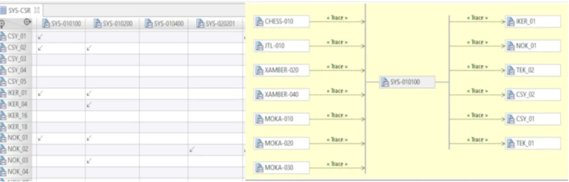
Modelio allowed us to edit requirements in both a diagram view and a tabular view (see Figure 2). The requirements were manually edited or automatically imported from other documents, e.g. MS Excel.
4.1.2. Architecture Modeling
At the architecture level, we used Class and Deployment diagrams. We limited modeling to a subset of UML to enforce the common understanding of the architecture and to simplify editing. In particular, we chose to use UML Components, Interfaces, Associations, Generalizations and Dependencies.
For collecting information about tool components, we defined a template for the architecture specification that included: a class diagram – to specify functional interfaces, tool components subordinates2 and the relation to the
conceptual tool set in the framework, and deployment diagrams – to
Figure 3: Editing Architecture and Documentation with Modelio.
tify the execution environment of the tool component. In addition, Package diagrams were used to define the high-level structure of the MegaM@Rt2 framework architecture.
For instance, Figure 3 shows that the MegaM@Rt2 framework architec-ture is composed of three parts corresponding to the three WPs of the project: System Engineering, Runtime Analysis, and Model and Traceability Manage-ment, respectively.
In Modelio, the documentation can be added in the textual notes (as shown in the lower part of Figure 3) or as separate documents. Both plain text and rich text notes are supported. In our work, we deliberately restricted editing to plain text notes to make sure that the generated documents are formatted correctly.
4.1.3. Requirements Traceability
Once the requirements have been specified, for each tool component we defined a traceability matrix to map case study requirements to framework requirements, and respectively framework requirements to tool purposes as
Figure 4: Example: Traceability Links Among the Tool Set, Framework and Case Study Requirements.
described by Activities 1 and 2 of the modeling approach in Figure 1. This allowed us to use traceability diagrams, as the one in Figure 4, to visualise the whole set of dependencies for a given requirement. This approach proved beneficial not only for the requirement analysis and tool set integration plan-ning, but also for identifying common interfaces for tool components and visualising gaps for the requirements analysis.
4.1.4. Generating Documents
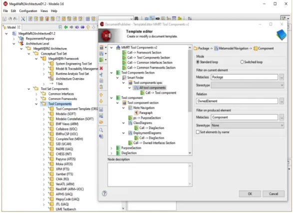
Modelio offers model query and document generation facilities that were used for editing and maintaining specifications in the project. The template editor (Figure 5) was particularly useful to implement custom extraction of model elements in order to create specific sections of the document.
In the example below, the template specifies that the generator will search for a Tool Components package, from which it will extract UML components in order to generate the tool section of the document. This document section will include introductory paragraph, Purpose subsection, subsections for all class and deployment diagrams as well as section on the owned interfaces.
When editing the architecture model, it is quite useful to see the gener-ation result. Thus, along with developing custom document templates, we integrated the document generation to the Modelio interface. That way reg-ular users could call the document generation directly from the tool using a context menu (Figure 6).
4.2. Collaborative Model Editing
Modelio Constellation [28] is the model sharing, collaborative editing, versioning and configuration management facility that allow modellers to
Figure 5: Example: Custom Document Generation Template for Individual Tools Section.
work together on the same common and shared model. Indeed, authoring the architecture deliverables in MegaM@Rt2 project required the contributions of 27 partners. Thus, around 50 users worked together on a single model. On a regular basis, users connected to the Constellation server, synchronized the local model with the central repository, edited the architecture and generated the documents with always updated templates. The version control was enabled by Apache Subversion3. The documentation templates and user
interfaces for document generation were developed continuously and had to be rolled out to the whole large team of modellers without interrupting the work process. It was important to provide versioning and conflict resolution when editing touched the common artifacts. Last but not least, several different deliverable were generated out of the same model. Therefore, the
3
branching facility allowed to fix the state when the deliverable were released.
Figure 6: Example: Architecture Document Generated with Modelio Document Publisher.
5. The MegaM@Rt2 Framework
In this section, we describe the MegaM@Rt2 Framework and its con-stituent parts. This framework is a result of the architecture specification approach described in Section 3. This description follows a common pattern: • We describe the high-level purpose of each component including
possi-ble roadmap for feature implementation;
• We outline the functional interfaces that help to figure out the main features and possible means for integration;
• We shortly detail the subordinates the constituent parts of each com-ponent;
Figure 7: MegaM@Rt2 Architecture Overview.
• For the individual tools, we clarify their relation to the MegaM@Framework conceptual tools.
All in all we intend to provide traceability linking use case requirements to conceptual tools of the framework to individual tools by partners.
The MegaM@Rt2 Framework is the main technical result of the MegaM@Rt2 project. The Framework regroups several interconnected tool sets including tool sets for Holistic System Engineering, Model and Traceability Manage-ment as well as for Runtime Analysis. Those tool sets are highly intercon-nected to achieve the goal of linking system models with the runtime analysis of large scale industrial systems. Figure 7 presents an architectural overview of the MegaM@Rt2 framework.
5.1. MegaM@Rt2 Systems Engineering Tool Set
Model-based design (MBD) has proven to be a powerful engineering method for developing highly complex and critical embedded systems. In most cases, software code in cyber-physical systems (CPSs) is written directly using low-level programming languages, and without following a model-driven development process. This makes the design and runtime traceability more difficult. Thus, these various development processes and practices need to be revisited and integrated accordingly, following such a model-based methodology. MegaM@Rt2 Systems Engineering approach integrates a vari-ety of current engineering practices like AADL, EAST-ADL, but also Mat-lab/Simulink, AUTOSAR and Method B or Modelica as required by the project’s industrial case studies. Artefacts (requirements specifications, de-sign models, software components) produced by each of these heterogeneous practices will be represented and combined in a global system model provid-ing a complete and holistic view of the CPS. Notably, the system model will include a precise specification of the desired functional and non-functional properties on the system level.
5.1.1. Purpose of System Engineering Tool Set Component
The System Engineering Tool Set must integrate, formalize and coordi-nate both general purpose and domain-specific existing languages, method-ologies and tools to support modelling, analysis and validation of complex heterogeneous systems.
5.1.2. Functional Interfaces
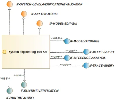
Following Figure 8 presents the functional interfaces (used & realized) of the System Engineering Tool Set.
5.1.3. Subordinates
Figure 9 shows the constituent parts of the MegaM@Rt2 System Engi-neering Tool Set.
The details of the subordinate components of the MegaM@Rt2 System Engineering Tool Set is as following:
• Metamodel and Support: This tool component provide functionality for working with standard and domain-specific metamodels. In addition, it provides the support services such as document generation.
Figure 8: Functional Interfaces (Used & Realized) of the MegaM@Rt2 System Engineering Tool Set.
• Requirement Modelling: Requirements modelling is an important part of the engineering process. This component provide tools for specifying, eliciting and tracing the requirements.
• System Architecture Modelling: MegaM@Rt2 targets bringing the run-time trace information to the system architecture level. This compo-nent deals with the system level of the engineering process.
• Detailed Design Modelling: This component provides capability to specify the detailed design models, which may include specific mod-els for software and hardware.
• Model Verification & Validation: This component provides a set of capabilities for design-time verification and validation.
5.1.4. Interfaces Specific to System Engineering Tool Set Component
The interfaces that are specific to System Engineering Tool Set Compo-nent are described below:
• IF-MODEL-EDIT-GUI: A Graphical User Interface (GUI) that sup-ports the user in all the modelling activities,
Figure 9: Constituent Parts (Subordinates) of the MegaM@Rt2 System Engineering Tool Set.
• IF-SYSTEM-MODEL: Interface to provide model artifacts for manage-ment and traceability purposes and exchange runtime analysis results and feedback,
• IF-SYSTEM-LEVEL-VERIFICATION&VALIDATION: Interface to pro-vide verification and validation technique and results for management and traceability purposes and exchange runtime analysis results and feedback,
• IF-DOC: Document generation facility is dedicated to derivation of various documentation from the models,
• IF-XMI: XML Metadata Interchange, Version 2.5.1, XMI.
Publication Date: June 2015 Link: https://www.omg.org/spec/XMI • IF-REQIF: OMG Requirements Interchange Format, Version 1.2,
Re-qIF Publication Date: July 2016 https://www.omg.org/spec/ReRe-qIF/ • IF-UML2: Object Management Group Unified Modeling Language, Version: 2.5.1 (UML2) Publication Date: December 2017 IPR Mode: RF-Limited Link: https://www.omg.org/spec/UML/
A specification defining a graphical language for visualizing, specify-ing, constructspecify-ing, and documenting the artifacts of distributed object systems.
• IF-SysML: OMG System Modeling Language, Version 1.5, SysML Pub-lication Date: May 2017 Link: https://www.omg.org/spec/SysML/ • IF-MARTE: Object Management Group (OMG): UML Profile for MARTE:
Modeling and Analysis of Real-Time Embedded Systems, Version 1.1 (MARTE) Publication Date: June 2011 Link: https://www.omg.org/ spec/MARTE
• IF-fUML: OMG Semantics of a Foundational Subset for Executable UML Models, Version 1.3, FUML
Publication Date: October 2017 Link: https://www.omg.org/spec/ FUML
• IF-DSL: this interface allows exchanging DSLs artifacts across different system engineering components, i.e. between different tools covering different parts of the system engineering process.
5.2. MegaM@Rt2 Runtime Analysis Tool Set
Model-based design approaches aim to obtain a running application thanks to productive models defined at design time. In the MegaM@Rt2 project, we apply such an approach by using and combining automated code gener-ation, model execution, runtime verificgener-ation, trace analysis [29] and online model-based testing. To achieve these goals, we propose to use executable models, which are related to aspect-oriented modelling (AOM) for models at runtime. Such models specify the behavior of an application and are either interpreted or compiled. The interpreted approach consists in implementing
an execution engine that takes as input a model and interprets its contents. The running system is then the couple formed by the execution engine and the model it interprets. The compiled view consists in generating another model or code for a dedicated execution platform. Executable versions of the system will be obtained at runtime either by automatically generating the code from runtime models or employing models which can be executed at runtime, either standalone or part of a system implementation. Therefore, we will develop specific code generators and model interpreters enabling to manage large-scale models at runtime, as well as model execution tools to per-form monitoring and tracing for analysis, online verification and model-based testing. In this context, traditional methods for analysis, online verification and model-based testing need also to be rethought and/or extended in order to fully tackle the specifics of runtime models and contained information. Verification and testing methods need to target large models that take into account traceability information and modularization (e.g., using AOM). 5.2.1. Purpose of Runtime Analysis Tool Set Component
The Runtime Analysis Tool Set Component realizes the following pur-poses:
• To use AOM techniques to facilitate code generation, runtime verifica-tion and validaverifica-tion.
• To support runtime analysis methods combining model-based develop-ment, validation and verification techniques.
• To use AOM techniques to facilitate code generation, runtime verifica-tion and validaverifica-tion.
• To support runtime analysis methods combining model-based develop-ment, validation and verification techniques.
• To be able to manage complex and large-scale models.
• To take advantage of the relationships between a set of runtime models. • To offer partial verification and validation methods, able to give an answer under strong time constraints but with only a certain confidence level.
Figure 10: Functional Interfaces (Used & Realized) of the MegaM@Rt2 Runtime Analysis Tool Set.
• To improve trace analysis results and localization of faults because of trace monitoring and online testing at runtime.
• To verify functional as well as non-functional properties in a synergic way by combining trace monitoring and online testing at runtime. • To enable the trace analysis tools to collect and analyse information
from different sources and using different techniques.
5.2.2. Functional Interfaces
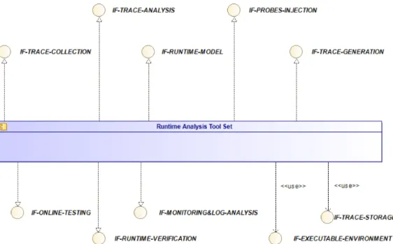
Following Figure 10 presents the functional interfaces (used & realized) of the Runtime Analysis Tool Set.
5.2.3. Subordinates
Figure 11 shows the constituent parts of the MegaM@Rt2 Runtime Anal-ysis Tool Set.
The details of the subordinate components of the MegaM@Rt2 Runtime Analysis Tool Set are as following:
Figure 11: Constituent Parts (Subordinates) of the MegaM@Rt2 Runtime Analysis Tool Set.
• Traces analysis tool set: Tool for reasoning on system properties based on traces analysis.
• Traces collection tool: Tool for capturing and collecting traces in a unified format for further analysis.
• Runtime verification and online testing tools: Algorithms and tools for verification of runtime models as well as model-based test generation and execution in a continuous and simultaneous manner.
Verification and testing/monitoring methods targeted at large models, and which take into account traceability information and modulariza-tion e.g, using AOM will be developed.
• Monitoring and logs analysis tool set: Tools for monitoring system, network events and execution traces to synthesize related runtime mod-els [30]. AIPHS supports the monitoring action on target by distribut-ing sniffer elements into target architecture. It stores logs on internal
buffers to be read at the end of the application execution. In the near future, logs will be stored automatically in memory thanks to a Direct Memory Access (DMA).
• Probes injection tool: Tool for probes injection to runtime artifacts based on the properties defined on the system level.
• Code generation facilities help to translate the various models into the code for specific targets such as Java, C++, C programming languages. 5.2.4. Interfaces Specific to Runtime Analysis Tool Set Component
The interfaces that are specific to Runtime Analysis Tool Set Component are described below:
• IF-EXECUTABLE-ENVIRONMENT: The Runtime and Analysis Tool Set has an interface with the executable environment in order to capture the traces of execution.
• IF-RUNTIME-MODEL: Interface to manage and configure model ex-ecution at runtime.
• IF-TRACE-GENERATION: Interface to manage and parameterize the generation of execution traces during runtime execution.
• IF-TRACE-COLLECTION: Interface to collect execution traces and to arrange/filter the related information into a given format.
• IF-TRACE-ANALYSIS: Interface to manage and execute runtime anal-ysis of collected execution traces.
• IF-PROBES-INJECTION: Interface to inject monitoring capabilities during execution at runtime.
• IF-RUNTIME-VERIFICATION: Interface to define properties to be checked and to configure their verification at runtime.
• IF-ONLINE-TESTING: Interface to configure and perform online test-ing.
• IF-MONITORING&LOG-ANALYSIS: Interface to configure monitor-ing directives and log analysis rules to be applied durmonitor-ing model or system execution.
5.3. MegaM@Rt2 Model & Traceability Management Tool Set
A key ingredient of MegaM@Rt2 is its dedicated support for traceability across all layers of the system design and execution, from highly specialized engineering practices to low-level log entries. This is what enables continuous integration practices at the Systems Engineering level. To make this possible, MegaM@Rt2 combines, in a highly scalable infrastructure, metamodeling and trace impact inference techniques.
Relying on the unification power of models and model-based techniques, megamodelling (also called Global Model Management or modeling in the large) provides efficient means of describing, handling and managing the many different heterogeneous artifacts (models, metamodels, transforma-tions, generators, logs etc.) implied by the large-scale industrial scenarios in MegaM@Rt, including the different kinds of relationships between them (refinement, extension, equality, combination, etc.). A megamodel is a model but a very special kind of a model, one whose model elements are models themselves. Therefore, a megamodel is way to register and manage all engi-neering resources available in a given project via model-based techniques.
Megamodelling will be used in MegaM@Rt2 in order to deal as efficiently as possible with the many involved (modelling) artifacts, workflows or con-figurations required at both design time and runtime. It will also be used to preserve the relevant traceability information between these two levels, notably in order to allow providing proper reusable feedback from runtime to design time. Thus, we will develop a methodological loop between models at design time and runtime levels. Relying on this same general approach as well as on common generic interfaces and language, we expect to develop sev-eral solutions covering different technical environments used by partners in the project. This includes a fully open source Eclipse/EMF-based solution, and a Modelio based-one.
5.3.1. Purpose of Model & Traceability Management Tool Set Component The Model & Traceability Management (MTM) Tool Set Component realizes the following purposes:
• To provide base model management capabilities.
• To provide model indexing/referencing capabilities for large sets of models.
• To provide model querying capabilities for large scale (sets of) models. • To provide model cartography/view capabilities over large sets of
in-terrelated models.
• To provide model cartography/view capabilities over large sets of in-terrelated models.
• To provide model versioning capabilities over large sets of interrelated models.
• To provide model access-control capabilities over large sets of interre-lated models.
• To provide model import/export capabilities from/to WP2-WP3 & other modeling solutions.
• To provide integration with source code repositories & continuous de-velopment solutions.
• To provide traceability capabilities between design/system models and runtime models.
• To provide inter-model trace storage capabilities for large scale (sets of) models.
• To provide inter-model trace querying capabilities for large scale (sets of) models.
• To provide inference capabilities from runtime models to design/system models.
• To provide automated inference computation capabilities (from runtime to design models).
• To provide inference information analysis capabilities (from runtime to design models).
5.3.2. Functional Interfaces
Following Figure 12 presents the functional interfaces (used & realized) of the Model & Traceability Management Tool Set.
Figure 12: Functional Interfaces (Used & Realized) of the MegaM@Rt2 Model & Trace-ability Management Tool Set.
5.3.3. Subordinates
Figure 13 shows the constituent parts of the MegaM@Rt2 Model & Trace-ability Management Tool Set.
The details of the subordinate components of the MegaM@Rt2 Model & Traceability Management Tool Set are as following:
• Base Model Management Infrastructure: Scalable infrastructure for performing base operations and manipulations on models of different kinds.
• Advanced Model Management Infrastructure: More advanced infras-tructure for dealing with complex model management activities: views, access-control, etc.
• Model Integration Infrastructure: Integration infrastructure for allow-ing model interchanges with other environments (notably model-based ones).
• Model Traceability Infrastructure: Infrastructure for dealing with inter-model traceability and feedback from the available traceability infor-mation.
5.3.4. Interfaces Specific to Model & Traceability Management Tool Set Com-ponent
The interfaces that are specific to Model & Traceability Management Tool Set Component are described below:
Figure 13: Constituent Parts (Subordinates) of the MegaM@Rt2 Model & Traceability Management Tool Set.
• IF-MODEL-CARTOGRAPHY: Advanced cartography capabilities for efficiently obtaining relevant views on models, either design/system ones or runtime ones, which are parts of large sets of interrelated mod-els.
• IF-MODEL-REFERENCING: Advanced referencing capabilities for ef-ficiently indexing different models, either design/system ones or run-time ones, which are parts of large sets of interrelated models.
• IF-MODEL-ACCESS-CONTROL: Advanced access-control capabili-ties for efficiently providing restricted views over different models, ei-ther design/system ones or runtime ones, which are parts of large sets of interrelated models.
• IF-MODEL-QUERY: Advanced querying capabilities for efficiently re-trieving different models, either design/system ones or runtime ones, which are parts of large sets of interrelated models.
• IF-MODEL-STORAGE: Advanced storing capabilities for efficiently saving different models, either design/system ones or runtime ones, which are parts of large sets of interrelated models.
• IF-MODEL-VERSIONING: Advanced versioning capabilities for effi-ciently managing over time different models, either design/system ones or runtime ones, which are parts of large sets of interrelated models.
• IF-INFERENCE-ANALYSIS: (Semi-)automated mechanisms to effi-ciently use at the system/design model-level the previously computed inference information (from the runtime models).
• IF-INFERENCE-COMPUTATION: Automated mechanisms to calcu-late relevant inference information from the runtime models (e.g. repre-senting execution traces) to be then further used at the system/design model-level.
• IF-TRACE-STORAGE: Advanced storing capabilities for efficiently saving traceability links between different models within large sets of interrelated models.
• IF-TRACE-QUERY: Advanced querying capabilities for retrieving al-ready existing traceability links between different models within large sets of interrelated models.
6. Gap Analysis and Roadmap 6.1. Gap Analysis
As mentioned in the introduction of this article, another goal of our ap-proach was to perform a gap analysis between the framework requirements derived from industrial needs and the tool purposes provided by different tool providers. During this process we identified two different types of gaps: unsatisfied framework requirements and unused tool component purposes. The unsatisfied framework requirements are framework requirements that are not satisfied by any tool component purpose. These requirements were addressed either by the tool providers in the project by creating additional development plans and corresponding tool purposes, or they were deferred to be satisfied by tools external to the project. The unused tool component purposes are those tool features that are available from the tools provided by tool providers participating in the project, but which are not explicitly requested by any case study provider. Creating such a list of unused tool pur-poses allowed tool providers to increase awareness about their tools among project participants, and in some cases resulted in case study providers in defining additional case study requirements.
Having all information centralized in one single model, different stake-holders involved in defining the MegaM@rt2 architecture were able to easily query and visualize the case study requirements, framework requirements and
Table 1: Example of Allocating Tool Purposes to Framework Requirements Depending on Their Release Date (MODELIO = https://www.modelio.org/, PAPYRUS = https:// www.eclipse.org/papyrus/, CERTIFYIT & MBEETLE = https://www.smartesting. com/) ID Baseline (M0) Initial (M15) Intermediate (M20) Final (M32) 1 MODELIO PAPYRUS, MODELIO PAPYRUS, MODELIO 2 CERTIFYIT MBEETLE
tool component purposes, and to incrementally update the mapping among them.
The gap analysis was done per work package. In total, we have elicited 106 case study requirements from 9 case study providers, and based on them we extracted 91 megaM@Rt framework requirements, as follows: 37 for WP2 System Engineering , 39 for WP3 Runtime Analysis, and 15 for WP4 -Model & Traceability Management. These were analyzed and linked against 28 tools which provided 223 tool purposes. During the gap analysis, we identified 2 case study requirements not satisfied by any tool purpose (one in WP2 and one in WP3) and 10 unused tool purposes (all in WP3).
6.2. Roadmap – Planning and Tracking
As discussed in Section 5, when we collected tool purpose specifications from the tool providers in MegaM@Rt2, we also collected information re-garding at which project milestone the tool feature corresponding to a tool purpose will be available. In MegaM@rt2, we have had four different release milestones: baseline - M0 (beginning of the project), initial - M15, interme-diate - M20, and final - M32. An excerpt from the generated roadmap for different framework requirements is shown in the Table 1.
By analyzing the release date of the tool purposes, we could also provide a general view of when different framework requirements will be completely satisfied in the project. In Figure 2 given in Section 4, one can observe that for instance framework requirement SYS-010100 is satisfied already at the beginning of the project (shown as ‘Baseline’), whereas framework require-ment SYS-000001 will be satisfied only at the final milestone of the project (shown as ‘Final’).
Having such a holistic approach to traceability and development plans for tool components allowed not only for individual project participants to
Table 2: An Example Status Report.
Purpose Properties Comments/Release
notes
Affected CSR MODELIO-060:
Modelio shall sup-port extra-functional properties in holistic system engineering approach. Criticality: High Re-lease: In-termediate Status: Postponed
Holistic system en-gineering support is postponed till fur-ther progress on the methodological aspects in WP2 and clarifica-tion of requirements and scenarios by the case study providers.
CSY 01, NOK 02, NOK 01, TRT 03, TEK 09, TRT 02, TRT 04, TRT 05
plan their activity in the project in detail, but it also facilitated the project level management activities. In addition, defining the initial plan for the development of the MegaM@Rt2 framework allowed us to easily monitor the evolution of the project and check for deviations for the plan at different reporting periods. For instance, WP leaders could see what set of features are planned for the framework components at which release for tracking.
The information provided by tool providers was regularly revisited and updated when needed to reflect the latest status of development. They in-dicated whether a feature development is planned, done, postponed or can-celled. The roadmap and traceability documentation enabled the WP leaders and case study providers to assess the progress of the entire framework and plan the case study execution accordingly. Table 2 provides an example of a status report where the MODELIO-060 tool purpose, that was supposed to be available at in the intermediate release, is delayed. In addition, it shows which are the case study requirements affected by this release.
7. Discussion and Conclusion
In this paper, we presented the generic approach we used in order to iden-tify and specify the architecture of the MegaM@Rt2 framework using model-driven principles and practices. Our approach, supported by corresponding tooling dedicated to its application in actual projects, enforced coordination and collaboration among many different stakeholders. This way, it also con-tributes to improve the manageability of complex projects. Indeed, the main benefit of our model-driven approach is that all information is collected from
different stakeholders and stored using one single common model (and using a single tool in our case). In our particular MegaM@Rt2 context, we further elaborated on the proposed framework and its various components centered around three different complementary tool sets.
The produced general architecture model was used as a common and shared reference (stored in a central repository), that every project part-ner can access and update using model versioning techniques. In addition, having all the required information in one single location allowed us 1) to constantly monitor the status of the process and to trace the requirements of the framework components, 2) to easily generate the necessary artifacts (such as documents, tables, diagrams) from the model whenever needed. Although the architectural modeling of the MegaM@Rt2 framework is realized using a subset of UML/SysML (for a better common understanding and to simplify editing, as mentioned in Section 4.1.2), the MegaM@Rt2 approach and tool sets themselves are by no way limited to any subset of UML or even to any particular metamodel or domain specification language (DSL). Indeed, many tools from these tool sets can potentially handle any model of any type when required in the context of a particular use case or scenario (cf. the different MegaM@Rt2 use cases and corresponding types of models for example).
It is important to notice that MegaM@Rt2 framework is meant to be generic in the way both functional and non-functional requirements (such as safety and security, for instance) can be expressed. The modeling lan-guages that are part of MegaM@Rt2 framework (e.g., MARTE and SysML) are well-suited for modeling a variety of requirements at different levels (e.g. from component to system level), as shown by existing studies [31, 32, 33]. Some industrial use cases from the project have specific non-functional re-quirements to meet, for example explicit safety rere-quirements of the train control management system for Bombardier Transportation, Sweden. These requirements can be met by the MegaM@Rt2 framework that provide such support, e.g., Modelio [34] or EMF Views [35] allow creating viewpoints with specific metamodels using MARTE sub-profiles (for example).
The MegaM@Rt2 framework is also designed to be extensible and open, in order to provide connectivity with other existing tools and technologies. The interfaces of the three complementary tool sets (cf. Sections 5.1.4, 5.2.4 and 5.3.4) have been specified to enable extensions with other tools and compo-nents implementing these interfaces. Thus, it is possible to integrate, import and then use external tools whenever necessary as part of a process following the MegaM@Rt2 approach. Moreover, in order to integrate non-compatible
models, there is always the option to design and implement model transfor-mations from/to model formats supported in MegaM@Rt2. Note that we are also currently working to standardize the framework interfaces as much as possible to facilitate extensibility. For example, Common Trace Format (CTF)4 is being investigated as a possible solution for sharing runtime data
in an uniform way and to better connect related tools altogether.
Using a model-based architectural approach, such as in the MegaM@Rt2 project, also comes with open challenges and current limitations. We discuss them in what follows.
The first of such challenges was that different project participants had different levels of familiarity with modeling tools in general (and with Mod-elio and Constellation in particular, as used in our MegaM@Rt2 context). This issue has been addressed by providing several project-wide online we-binars along with proper documentation on describing how the tools can be used to support the architecture specification approach. The tooling support team was helpful in solving the licensing issues, helping with installation and resolving model versioning conflicts. This contributed to facilitate the de-ployment and adoption of the proposed approach and corresponding tooling. A second challenge came from the fact that 50 modellers worked collabo-ratively with the models. This could potentially trigger many inconsistencies, conflicts and omissions in the collected information. We were able to support model versioning and collaborative modeling thanks to the features provided by the selected repository solution (Constellation). In addition, we decided to split the model in several parts (one corresponding to each work package) and we provided clear guidelines on how the it is/has to be organized. In this way, we have been able to ensure that our central architectural model stays consistent and correctly maintainable over time.
A third challenge came from the limitations of the selected tools. For instance, there were different restrictions on how the styling of the documents generated from the models could be configured and how the information could be visualized using different types of diagrams. Moreover, manual effort is also required in order to create the initial document templates and to configure the document generators accordingly. However, once all this generation infrastructure was created, it could be easily reused whenever relevant. It allowed to (re)produce the targeted documentation in an efficient
(semi-automated) way, and as many times as needed.
In addition to the challenges and limitations discussed before, some in-dustrial partners were already using an existing company/internal tool chain that is not supposed to be part of our project tool sets. In this case, they still provided their requirements which were then mapped (currently manually) in order to fit with the MegaM@Rt2 tool set capabilities. However, in such cases, the industrial partners had to perform an additional validation step: they had to consider the acceptance of their requirements using both the MegaM@Rt2 tool set capabilities as well as the capabilities of their in-house solution. Despite of this, and from a more general project consortium per-spective, the benefits of using the common shared approach and tooling we proposed are still interesting.
Overall, the feedback collected from the different partners (industrial and academic ones) in the MegaM@Rt2 project showed that the application we made of our approach was mostly positive in terms of both productivity and user experience. Moreover, we already plan to capitalize on this effort. Thus, the corresponding tooling support that has been developed and deployed will be further reused in the context of other architecture documents later in the project, and possibly in the context of other large collaborative projects in the future.
Acknowledgments
This project has received funding from the Electronic Component Sys-tems for European Leadership Joint Undertaking under grant agreement No. 737494. This Joint Undertaking receives support from the European Union’s Horizon 2020 research and innovation program and from Sweden, France, Spain, Italy, Finland and Czech Republic. Wasif Afzal is also sponsored in part by the Swedish Knowledge Foundation under Grant 20160139 (Test-Mine).
References
[1] ECSEL JU MegaM@Rt2 Project Website, https://megamart2-ecsel. eu/, online; accessed 15 January 2019.
[2] W. Afzal, H. Bruneliere, D. D. Ruscio, A. Sadovykh, S. Mazzini, E. Car-iou, D. Truscan, J. Cabot, A. Gmez, J. Gorroogoitia, L. Pomante,
P. Smrz, The MegaM@Rt2 ECSEL project: MegaModelling at Runtime – Scalable model-based framework for continuous development and run-time validation of complex systems, Microprocessors and Microsystems 61 (2018) 86 – 95.
[3] W. Afzal, H. Bruneliere, D. D. Ruscio, A. Sadovykh, S. Mazzini, E. Cariou, D. Truscan, J. Cabot, D. Field, L. Pomante, P. Smrz, The MegaM@Rt2 ECSEL project: MegaModelling at runtime – Scalable model-based framework for continuous development and runtime val-idation of complex systems, in: 2017 Euromicro Conference on Digital System Design (DSD), 2017.
[4] B. Fitzgerald, K.-J. Stol, Continuous software engineering: A roadmap and agenda, Journal of Systems and Software 123 (2017) 176 – 189. [5] ISO/IEC/IEEE International Standard - Systems and Software
Engineering – Life cycle processes – Requirements engineering, ISO/IEC/IEEE 29148:2018(E) (2018) 1–104.
[6] ISO/IEC Systems and Software Engineering – Systems and software Quality Requirements and Evaluation (SQuaRE) – System and software quality models, ISO/IEC 25010:2011 (2011) 1–34.
[7] D. Di Ruscio, R. F. Paige, A. Pierantonio, Guest editorial to the spe-cial issue on success stories in model driven engineering, Sci. Comput. Program. 89 (PB) (2014) 69–70.
[8] OMG: Model Driven Architecture (MDA) Guide rev. 2.0, http://www. omg.org/cgi-bin/doc?ormsc/14-06-01, online; accessed 15 January 2019.
[9] A. Sadovykh, A. Bagnato, D. Truscan, P. Pierini, H. Bruneliere, A. Gomez, J. Cabot, O. Avila-Garc´ıa, W. Afzal, A Tool-supported Approach for Building the Architecture and Roadmap in MegaM@Rt2 Project, in: The 6th international Conference in Software Engineering for Defense Applications (SEDA 2018), Vol. Advances in Intelligent Sys-tems and Computing: Selected Papers from the 6th international Con-ference in Software Engineering for Defense Applications (SEDA 2018), Springer, 2018.
[10] S. Ali, L. C. Briand, A. Arcuri, S. Walawege, An industrial application of robustness testing using aspect-oriented modeling, uml/marte, and search algorithms, in: J. Whittle, T. Clark, T. K¨uhne (Eds.), Model Driven Engineering Languages and Systems, Springer Berlin Heidelberg, Berlin, Heidelberg, 2011, pp. 108–122.
[11] B. Selic, The pragmatics of model-driven development, IEEE Software 20 (5) (2003) 19–25.
[12] T. Robert, V. Perrier, COFLUENT Methodology for UML: UML SysML MARTE Flow for CoFluent Studio, https: //www.next-community.de/fileadmin/media/whitepaper/files/ 163_cofluent_methodology_for_uml_wp_v1_0.pdf, online; accessed 30 May 2019.
[13] A. Koudri, J. Champeau, J.-C. Le Lann, V. Leilde, Mopcom method-ology: Focus on models of computation, in: T. K¨uhne, B. Selic, M.-P. Gervais, F. Terrier (Eds.), Modelling Foundations and Applications, Springer Berlin Heidelberg, Berlin, Heidelberg, 2010, pp. 189–200. [14] J. Vidal, F. de Lamotte, G. Gogniat, P. Soulard, J. Diguet, A co-design
approach for embedded system modeling and code generation with uml and marte, in: 2009 Design, Automation Test in Europe Conference Exhibition, 2009.
[15] A. W. Liehr, K. J. Buchenrieder, H. S. Rolfs, U. Nageldinger, Gen-eration of MARTE Allocation Models fromActivity Threads, Springer Netherlands, Dordrecht, 2009.
[16] S. Ali, T. Yue, L. Briand, Assessing quality and effort of applying aspect state machines for robustness testing: A controlled experiment, in: 2013 IEEE Sixth International Conference on Software Testing, Verification and Validation, 2013.
[17] S. Ali, T. Yue, L. C. Briand, Does aspect-oriented modeling help improve the readability of uml state machines?, Software and Systems Modeling 13 (3) (2014) 1189–1221.
[18] M. Wimmer, A. Schauerhuber, G. Kappel, W. Retschitzegger, W. Schwinger, E. Kapsammer, A survey on uml-based aspect-oriented design modeling, ACM Computing Surveys 43 (4) (2011) 28:1–28:33.
[19] S. Chiba, R. Ishikawa, Aspect-oriented programming beyond depen-dency injection, in: Proceedings of the 19th European Conference on Object-Oriented Programming, Springer-Verlag, Berlin, Heidelberg, 2005.
[20] M. Szvetits, U. Zdun, Systematic literature review of the objectives, techniques, kinds, and architectures of models at runtime, Software & Systems Modeling 15 (1) (2016) 31–69.
[21] G. Blair, N. Bencomo, R. B. France, Models@ run.time, Computer 42 (10) (2009) 22–27.
[22] E. Cariou, O. Le Goaer, F. Barbier, S. Pierre, Characterization of adapt-able interpreted-dsml, in: Proceedings of the 9th European Conference on Modelling Foundations and Applications, Springer-Verlag, Berlin, Heidelberg, 2013.
[23] A. Filieri, C. Ghezzi, G. Tamburrelli, Run-time efficient probabilistic model checking, in: Proceedings of the 33rd International Conference on Software Engineering, ACM, New York, NY, USA, 2011.
[24] A. A. Bayazit, S. Malik, Complementary use of runtime validation and model checking, in: Proceedings of the 2005 IEEE/ACM International Conference on Computer-aided Design, IEEE Computer Society, Wash-ington, DC, USA, 2005, pp. 1052–1059.
[25] H. Bruneliere, S. Mazzini, A. Sadovykh, The MegaM@Rt2 Approach and Tool Set, in: DeCPS Workshop, 22nd International Conference on Reliable Software Technologies - Ada-Europe 2017, 2017.
[26] OMG: OMG Systems Modeling Language (OMG SysML), Ver. 1.4, http://www.omg.org/spec/SysML/1.4/, online; accessed 15 January 2019.
[27] OMG: Unified Modeling Language (UML), Ver. 2.5, http://www.omg. org/spec/UML/2.5/, online; accessed 15 January 2019.
[28] P. Desfray, Model repositories at the enterprises and systems scale the modelio constellation solution, in: 2015 3rd International Conference on Model-Driven Engineering and Software Development (MODEL-SWARD), 2015.
[29] D. Flemstr¨om, E. Enoiu, W. Afzal, D. Sundmark, T. Gustafsson, A. Ko-betski, From natural language requirements to passive test cases using guarded assertions, in: 2018 IEEE International Conference on Software Quality, Reliability and Security (QRS), 2018.
[30] D. Brahneborg, W. Afzal, A. Causevic, A black-box approach to latency and throughput analysis, in: 2017 IEEE International Conference on Software Quality, Reliability and Security Companion (QRS-C), 2017. [31] A. Tsadimas, M. Nikolaidou, D. Anagnostopoulos, Extending sysml to
explore non-functional requirements: The case of information system design, in: Proceedings of the 27th Annual ACM Symposium on Applied Computing, ACM, New York, NY, USA, 2012.
[32] M. R. Sena Marques, E. Siegert, L. Brisolara, Integrating UML, MARTE and sysml to improve requirements specification and traceability in the embedded domain, in: 12th IEEE International Conference on Industrial Informatics, 2014.
[33] M. Jamro, Sysml modeling of functional andnon-functional require-ments foriec61131-3 control systems, in: R. Szewczyk, C. Zieli´nski, M. Kaliczy´nska (Eds.), Progress in Automation, Robotics and Mea-suring Techniques, Springer International Publishing, Cham, 2015, pp. 91–100.
[34] A. Bagnato, L. S. Indrusiak, I. R. Quadri, M. Rossi, M. Bourdell´es, S. Li, I. Quadri, E. Brosse, A. Sadovykh, E. Gaudin, F. Mallet, A. Goknil, D. George, J. Kreku, Fostering analysis from industrial em-bedded systems modeling, in: A. Bagnato, L. S. Indrusiak, I. R. Quadri, M. Rossi (Eds.), Handbook of Research on Embedded Systems Design, IGI Global, Hershey, PA, USA, 2014, Ch. 11, pp. 283–300.
[35] H. Bruneliere, F. M. de Kerchove, G. Daniel, J. Cabot, Towards scalable model views on heterogeneous model resources, in: Proceedings of the 21th ACM/IEEE International Conference on Model Driven Engineering Languages and Systems (MODELS 2018), ACM, 2018, pp. 334–344.