HAL Id: tel-01653831
https://hal.inria.fr/tel-01653831v2
Submitted on 20 Apr 2018
HAL is a multi-disciplinary open access
archive for the deposit and dissemination of sci-entific research documents, whether they are pub-lished or not. The documents may come from teaching and research institutions in France or abroad, or from public or private research centers.
L’archive ouverte pluridisciplinaire HAL, est destinée au dépôt et à la diffusion de documents scientifiques de niveau recherche, publiés ou non, émanant des établissements d’enseignement et de recherche français ou étrangers, des laboratoires publics ou privés.
Anna Giannakou
To cite this version:
Anna Giannakou. Self-adaptable Security Monitoring for IaaS Cloud Environments. Cryptography and Security [cs.CR]. INSA de Rennes, 2017. English. �NNT : 2017ISAR0021�. �tel-01653831v2�
pour obtenir le titre de DOCTEUR DE L’INSA RENNES Spécialité : Informatique
Anna Giannakou
ECOLE DOCTORALE : Matisse LABORATOIRE : Irisa
Self-adaptable Security
Monitoring for IaaS
Cloud Environments
Thèse soutenue le 06.07.2017
devant le jury composé de :
Eric Totel
Professeur, Centrale-Supélec / Président
Sara Bouchenak
Professeur, INSA Lyon / Rapporteur
Hervé Debar
Professeur, Télécom SudParis / Rapporteur
Eddy Caron
Maître de Conférences, HDR, ENS Lyon / Examinateur
Stephen Scott
Professeur, Tennessee Tech University / Examinateur
Christine Morin
Directrice de Recherche, INRIA Rennes / Co-directrice de thèse
Jean-Louis Pazat
Professeur, INSA Rennes / Directeur de thèse
Louis Rilling
Self-adaptable Security Monitoring for IaaS
Cloud Environments
Anna Giannakou
o National
▪ Workshops :
• Giannakou, Anna, Louis Rilling, Frédéric Majorczyk, Jean-Louis
Pazat, and Christine Morin. “Self Adaptation in Security Monitoring for IaaS clouds”. In: EIT Digital Future Cloud
symposium, Rennes, France, October 19-20, 2015
o International
▪ Conferences :
• Giannakou,Anna,Louis Rilling,Jean-Louis Pazat,andChristine
Morin.“AL-SAFE: A Secure Self-Adaptable Application-Level Firewall for IaaS Clouds”. In: 2016 IEEE International
Conference on Cloud Computing Technology and Science, CloudCom 2016,Luxembourg, Luxembourg, December 12-15, 2016, pp. 383–390
•
Giannakou, Anna, Louis Rilling, Jean-Louis Pazat, FrédéricMajorczyk, and Chris- tine Morin. “Towards Self Adaptable Security Monitoring in IaaS Clouds”. In: 15th IEEE/ACM
International Symposium on Cluster, Cloud and Grid
Computing, CC- Grid 2015, Shenzhen, China, May 4-7, 2015,
pp. 737–740.
▪
Workshops :
•
Giannakou, Anna, Louis Rilling, Jean-Louis Pazat, andChristine Morin. “How to Secure Application-Level Firewalls in
IaaS Clouds”. In: International Workshop on Cloud Data and
First and foremost I would like to like to thank my advisors for their outstanding guidance and support throughout the duration of this thesis. Christine, thank you for continuously reviewing my work, offering important insights and improvements. Your advice regarding my professional development after the PhD helped me make important decisions about my future. During the last three and a half years you have been a role model for me as a woman in research. Louis, words cannot express how grateful I am for your guidance and support all these years. You have taught me so many things and helped me achieve my goals at so many different levels. Thank you for showing me all these new directions and possibilities and for helping me grow as a researcher. Also, thank you for tirelessly listening me complain about not having enough results :). Jean-Louis, I am grateful for your guidance throughout the whole process.
Furthermore, I would like to thank the members of my committee and especially the reviewers Sara Bouchenak and Herve Debar for evaluating my work. Special thanks goes out to all the members of the Myriads team for creating a warm and welcoming atmo-sphere at the office. David, Yunbo and Amir, for all of our discussions and for being such wonderful people to interact with. Deb and Sean, thank you for hosting me at Lawrence Berkeley National Lab for my three month internship and for allowing me to explore new research directions.
This thesis would not have been possible without the endless love and support of my friends and family. Genc, I am so grateful that I have met you and I am proud to call you my buddinis. Thank you for listening my complains offering helpful insights every time I invaded your office :). Bogdan and Mada, you have both been so wonderful and special to me. To Tsiort, Magnum, Ziag and Fotis thank you for your honest and deep support throughout these years from thousands of miles away. I love and miss you guys so much. To Irene, you have been nothing less than exceptional, kolitoula. I cannot express how deeply grateful I am for your endless encouragement and advice all this time. To Iakovos, thank you for your stoic comments and for all of our arguments :). To Eri, thank you for all your support and your clear-headed guidance throughout these years. You are admirable and you have given me so much. To my parents, thank you for your love, patience and support that has allowed me to pursue my ambitions. Thank you for raising me as a strong independent person and for showing me the benefits of persistence. To my sister Maria, thank you for being there, always.
Finally, the biggest thank you goes out to a single person that has been by my side for the last five years. Ismael, words cannot describe how grateful I am for all the things that you have given me throughout this period. Thank you for helping me break my personal deadlocks in so many levels and for adding all these new dimensions in my life. I could not have done this without you and I will never forget that. I love you, always, my sun and stars.
1 Introduction 11 1.1 Context . . . 11 1.2 Motivation . . . 11 1.3 Objectives . . . 12 1.3.1 Self-Adaptation . . . 12 1.3.2 Tenant-Driven Customization . . . 12
1.3.3 Security and Correctness . . . 13
1.3.4 Cost Minimization . . . 13
1.4 Contributions . . . 13
1.4.1 A Self-Adaptable Security Monitoring Framework . . . 13
1.4.2 SAIDS . . . 13
1.4.3 AL-SAFE . . . 14
1.5 Thesis Outline . . . 14
2 State of the Art 17 2.1 Autonomic Computing . . . 17
2.1.1 What is Autonomic Computing? . . . 17
2.1.2 Characteristics . . . 17
2.1.3 The Role of the Manager . . . 18
2.2 Cloud Computing . . . 19
2.2.1 What is Cloud Computing? . . . 19
2.2.2 Characteristics . . . 20
2.2.3 Service Models . . . 20
2.2.4 Deployment Models . . . 22
2.2.5 Dynamic Events in Iaas Clouds and Cloud Adaptation . . . 23
2.3 Virtualization . . . 24
2.3.1 Server Virtualization Components . . . 24
2.3.2 Server Virtualization . . . 24
2.3.3 Network Virtualization and Network Management in IaaS Clouds . . 27
2.4 Security Threats . . . 29
2.4.1 Security Threats in Information Systems . . . 29
2.4.2 Security Threats in Cloud Environments . . . 32
2.4.3 Summary . . . 33
2.5 Security Monitoring . . . 33
2.5.1 What is Security Monitoring? . . . 33
2.5.2 Security Monitoring in Cloud Environments . . . 38
2.6 Summary . . . 50 3
3 A Self-Adaptable Security Monitoring Framework for IaaS Clouds 53 3.1 Introduction . . . 53 3.2 System Model . . . 54 3.3 Threat Model . . . 54 3.4 Objectives . . . 55 3.4.1 Self Adaptation . . . 55 3.4.2 Tenant-Driven Customization . . . 55
3.4.3 Security and Correctness . . . 56
3.4.4 Cost Minimization . . . 56 3.5 Example Scenario . . . 56 3.6 Adaptation Process . . . 57 3.7 Architecture . . . 58 3.7.1 High-Level Overview . . . 58 3.7.2 Tenant-API . . . 59 3.7.3 Security Devices . . . 62 3.7.4 Adaptation Manager . . . 62
3.7.5 Infrastructure Monitoring Probes . . . 64
3.7.6 Component Dependency Database . . . 64
3.8 Implementation . . . 65
3.8.1 Adaptation Manager . . . 65
3.8.2 Infrastructure Monitoring Probe . . . 67
3.9 Summary . . . 67
4 SAIDS: A Self-Adaptable Intrusion Detection System for IaaS Cloud Environments 69 4.1 Objectives . . . 69
4.2 Models and Architecture . . . 70
4.2.1 Architecture . . . 70
4.3 Security Threats . . . 72
4.3.1 SAIDS Configuration Files . . . 72
4.3.2 LIDS Rules . . . 73
4.3.3 SAIDS Adaptation Sources . . . 73
4.3.4 Connection Between SAIDS Components . . . 73
4.3.5 External Traffic . . . 73
4.4 Adaptation process . . . 74
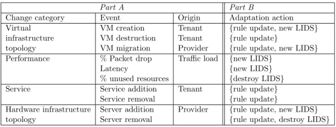
4.4.1 Events Triggering Adaptation . . . 74
4.4.2 Adaptation Process . . . 74 4.4.3 Topology-Related Change . . . 75 4.4.4 Traffic-Related Change . . . 76 4.4.5 Service-Related Change . . . 76 4.5 Implementation . . . 77 4.6 Evaluation . . . 78
4.6.1 Objectives of the Evaluation . . . 78
4.6.2 Experimentation Methodology . . . 81
4.6.3 Result Analysis . . . 83
5 AL-SAFE: A Secure Self-Adaptable Application-Level Firewall for IaaS
Clouds 93
5.1 Requirements . . . 93
5.1.1 Why Should we Secure an Application-level Firewall . . . 94
5.1.2 Security and Visibility . . . 94
5.1.3 Self-Adaptable Application-Level Firewall . . . 94
5.2 Models and Architecture . . . 95
5.2.1 Events that Trigger Adaptation . . . 95
5.2.2 Component Description . . . 95 5.3 Adaptation Process . . . 97 5.3.1 Security Threats . . . 100 5.4 Implementation . . . 101 5.4.1 Edge Firewall . . . 101 5.4.2 Switch-Level Firewall . . . 101 5.4.3 VMI . . . 101
5.4.4 Information Extraction Agent . . . 104
5.4.5 Rule Generators . . . 105
5.5 Evaluation Methodology . . . 105
5.5.1 Objectives of the Evaluation . . . 105
5.5.2 Experimentation Methodology . . . 107
5.6 Evaluation Results . . . 114
5.6.1 Performance and Cost Analysis . . . 114
5.6.2 Correctness Analysis . . . 122 5.6.3 Limitations . . . 123 5.7 Summary . . . 124 6 Conclusion 125 6.1 Contributions . . . 125 6.2 Future Work . . . 127 6.2.1 Short-Term Goals . . . 127 6.2.2 Mid-Term Goals . . . 128 6.2.3 Long-Term Goals . . . 130
Annexe A R´esum´e en fran¸cais 143 A.1 Contexte . . . 143
A.2 Motivation . . . 144
A.3 Objectifs . . . 144
A.3.1 Auto-adaptation . . . 144
A.3.2 Personnalisation . . . 145
A.3.3 S´ecurit´e et correction . . . 145
A.3.4 Minimisation des coˆuts . . . 145
A.4 Contributions . . . 145
A.4.1 Un syst`eme de supervision de s´ecurit´e auto-adaptatif . . . 146
A.4.2 SAIDS . . . 146
A.4.3 AL-SAFE . . . 147
A.5 Perspectives . . . 147
A.5.1 Perspectives `a court terme . . . 147
A.5.2 Perspectives `a moyen terme . . . 147
2.1 The MAPE control loop . . . 19
2.2 The OpenStack architecture . . . 22
2.3 The SDN architecture . . . 28
2.4 Information system with different security devices contributing to security monitoring . . . 34
2.5 A DMZ example . . . 37
2.6 Hypervisor and host OS kernel . . . 39
2.7 The Cloud IDS architecture as in [1] . . . 43
2.8 The Livewire architecture as in [2] . . . 44
2.9 CloudSec architecture as in [3] . . . 46
3.1 An example of a cloud hosted information system . . . 56
3.2 The framework’s architecture . . . 59
3.3 The framework’s different levels . . . 60
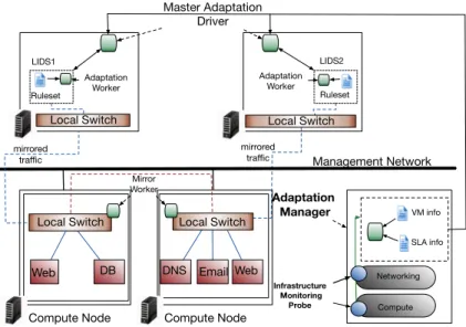
4.1 SAIDS architecture . . . 71
4.2 Migration time with and without SAIDS . . . 84
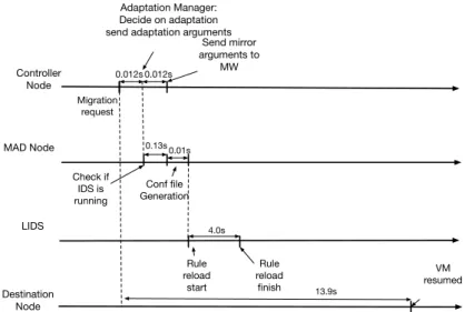
4.3 Adaptation time breakdown when SAIDS only reconfigures the enforced ruleset inside the LIDS . . . 84
4.4 Adaptation time breakdown when SAIDS has to start a new LIDS, dis-tribute traffic and create a mirroring tunnel . . . 85
4.5 MAD scalability setup . . . 86
4.6 MAD response time . . . 86
4.7 AM scalability setup . . . 87
4.8 AM response time . . . 88
5.1 The AL-SAFE architecture with the Adaptation Manager . . . 96
5.2 Steps of the AL-SAFE adaptation . . . 98
5.3 The migration request arrives between two introspections . . . 99
5.4 The migration request arrives during an introspection . . . 99
5.5 LibVMI stack . . . 102
5.6 Adaptation process flow chart . . . 103
5.7 Snapshot-Introspection relationship . . . 104
5.8 TCP server setup . . . 111
5.9 TCP client setup . . . 112
5.10 UDP setup . . . 113
5.11 Migration time with and without adaptation . . . 114
5.12 Breakdown of each phase in seconds . . . 115
5.13 Impact of the introspection period on kernel compilation time . . . 115 7
5.14 Impact of the introspection period on server throughput . . . 116
5.15 Request service time for different times in the introspection cycle . . . 117
5.16 Cases of request arrival time with respect to the introspection cycle . . . 117
5.17 Impact of the introspection period on network throughput . . . 118
5.18 Cases of request arrival time with respect to the introspection cycle . . . 119
5.19 Inbound TCP connection establishment time . . . 120
5.20 Outbound TCP connection establishment time . . . 121
3.1 The VM info table . . . 65
3.2 The Device info table . . . 65
4.1 Events that trigger adaptation . . . 74
4.2 Resource consumption of the AM component . . . 89
5.1 Events that trigger adaptation . . . 95
5.2 Resource consumption of the introspection component . . . 122
Introduction
1.1
Context
Server virtualization enables on-demand allocation of computational resources (e.g. CPU and RAM) according to the pay-as-you-go model, a business model where users (referred to as tenants) are charged only for as much as they have used. One of the main cloud models that has gained significant attention over the past few years is the Infrastructure as a Service model where compute, storage, and network resources are provided to tenants in the form of virtual machines (VMs) and virtual networks. Organizations outsource part of their information systems to virtual infrastructures (composed of VMs and virtual networks) hosted on the physical infrastructure of the cloud provider. The terms that regulate the resource allocation are declared in a contract signed by the tenants and the cloud provider, the Service Level Agreement (SLA) [4]. Few of the main benefits of the IaaS cloud include: flexibility in resource allocation, illusion of unlimited capacity of computational and network resources and automated administration of complex virtualized information systems.
Although shifting to the cloud might provide significant cost and efficiency gains, secu-rity continues to remain one of the main concerns in the adoption of the cloud model [5]. Multi-tenancy, one of the key characteristics of a cloud infrastructure, creates the possi-bility of legitimate VMs being colocated with malicious, attacker-controlled VMs. Con-sequently, attacks towards cloud infrastructures may originate from inside as well as the outside of the cloud environment [6]. A successful attack could allow attackers to gain access and manipulate cloud-hosted data including legitimate user’s account credentials or even gain complete control of the cloud infrastructure and turn it into a malicious entity [7]. Although traditional security techniques such as traffic filtering or traffic in-spection can provide a certain level of protection against attackers, they are not enough to tackle sophisticated threats that target virtual infrastructures. In order to provide a security solution for cloud environments, an automated self-contained security architecture that integrates heterogeneous security and monitoring tools is required.
1.2
Motivation
In a typical IaaS cloud environment, the provider is responsible for the management and maintenance of the physical infrastructure while tenants are only responsible for managing their own virtualized information system. Tenants can make decisions regarding VM life-cycle and deploy different types of applications on their provisioned VMs. Since deployed
applications may have access to sensitive information or perform critical operations, ten-ants are concerned with the security monitoring of their virtualized infrastructure. These concerns can be expressed in the form of monitoring requirements against specific types of threats. Security monitoring solutions for cloud environments are typically managed by the cloud provider and are composed of heterogeneous tools for which manual configura-tion is required. In order to provide successful detecconfigura-tion results, monitoring soluconfigura-tions need to take into account the profile of tenant-deployed applications as well as specific tenant security requirements.
A cloud environment exhibits a very dynamic behavior with changes that occur at different levels of the cloud infrastructure. Unfortunately, these changes affect the ability of a cloud security monitoring framework to successfully detect attacks and preserve the integrity of the cloud infrastructure [8]. Existing cloud security monitoring solutions fail to address changes and take necessary decisions regarding the reconfiguration of the security devices. As a result, new entry points for malicious attackers are created which may lead to a compromise of the whole cloud infrastructure. To our knowledge, there still does not exist a security monitoring framework that is able to adapt its components based on different changes that occur in a cloud environment.
The goal of this thesis is to design and implement a self-adaptable security monitoring framework that is able to react to dynamic events that occur in a cloud infrastructure and adapt its components in order to guarantee that an adequate level of security monitoring for tenant’s virtual infrastructures is achieved.
1.3
Objectives
After presenting the context and motivation for this thesis we now define a set of objectives for a self-adaptable security monitoring framework.
1.3.1 Self-Adaptation
A self-adaptable security monitoring framework should be able to adapt its components based on different types of dynamic events that occur in a cloud infrastructure. The framework should perceive these events as sources of adaptation and take subsequent actions that affect its components. The adaptation process may alter the configuration of existing monitoring devices or instantiate new ones. The framework may decide to alter the computational resources available to a monitoring device (or a subset of monitoring devices) in order to maintain an adequate level of monitoring. Adaptation of the amount of computational resources should also be performed in order to free under-utilized resources. The framework should make adaptation decisions in order to guarantee that a balanced trade-off between security, performance and cost is maintained at any given moment. Adaptation actions can affect different components and the framework should be able to perform these actions in parallel.
1.3.2 Tenant-Driven Customization
Tenant requirements regarding specific monitoring cases should be taken into account from a self-adaptable security monitoring framework. The framework should be able to guaran-tee that adequate monitoring for specific tenant-requested types of threats will be provided. The monitoring request could refer to a tenant’s whole virtual infrastructure or to a spe-cific subset of VMs. The framework should provide the requested type of monitoring until
the tenant requests otherwise or the subset of VMs that the monitoring type is applied to no longer exists. Furthermore, the framework should take into account tenant-defined (through specific SLAs) thresholds that refer to the quality of the monitoring service or to the performance of specific types of monitoring devices.
1.3.3 Security and Correctness
Deploying a self-adaptable security monitoring framework should not add new vulnera-bilities in the monitored virtual infrastructure or in the provider’s infrastructure. The adaptation process and the input sources required should not create new entry points for an attacker. Furthermore, a self-adaptable security monitoring framework should be able to guarantee that an adequate level of monitoring is maintained throughout the adaptation process. The adaptation process should not intervene with the ability of the framework to correctly detect threats.
1.3.4 Cost Minimization
Deploying a self-adaptable security monitoring framework should not significantly impact the trade-off between security and cost for both tenants and the provider. On the ten-ant’s side a self-adaptable security monitoring framework should not significantly impact performance of the applications that are hosted in the virtual infrastructure regardless of the application profile (compute- or network-intensive). On the provider’s side, the abil-ity to generate profit by leasing it’s computational resources should not be significantly affected by the framework. Deploying such a framework should not impose a significant penalty in normal cloud operations (e.g. VM migration, creation, etc). Furthermore, the amount of computational resources dedicated to the self-adaptable framework’s compo-nents should reflect an agreement between tenants and the provider for the distribution of computational resources.
1.4
Contributions
In order to achieve the objectives presented in the previous section, we design a self-adaptable security monitoring that is able to address limitations in existing monitoring frameworks and tackle dynamic events that occur in a cloud infrastructure. In this thesis we detail how we designed, implemented, and evaluated our contributions: a generic self-adaptable security monitoring framework and two instantiations with intrusion detection systems and firewalls.
1.4.1 A Self-Adaptable Security Monitoring Framework
Our first contribution is the design of a self-adaptable security monitoring framework that is able to alter the configuration of its components and adapt the amount of computational resources available to them depending on the type of dynamic event that occurs in a cloud infrastructure. Our framework achieves self-adaptation and tenant-driven customization while providing an adequate level of security monitoring through the adaptation process.
1.4.2 SAIDS
Our second contribution constitutes the first instantiation of our framework focusing on network-based intrusion detection systems (NIDS). NIDSs are key components of a security
monitoring infrastructure. SAIDS achieves the core framework’s objectives while providing a scalable solution for serving parallel adaptation requests. Our solution is able to scale depending on the load of monitored traffic and the size of the virtual infrastructure. SAIDS maintains an adequate level of detection while minimizing the cost in terms of resource consumption and deployed application performance.
1.4.3 AL-SAFE
Our third contribution constitutes the second instantiation of our framework focusing on application-level firewalls. AL-SAFE uses virtual machine introspection in order to create a secure application-level firewall that operates outside the monitored VM but retains inside-the-VM visibility. The firewall’s enforced rulesets are adapted based on dynamic events that occur in a virtual infrastructure. AL-SAFE offers a balanced trade-off between security, performance and cost.
1.5
Thesis Outline
This thesis is organized as follows:
Chapter 2 reviews the state of the art while making important observations in the area of cloud computing security focusing on both industrial and academic solutions. We start by providing the context in which the contributions of this thesis were developed while describing fundamental concepts of autonomic and cloud computing. Security threats for traditional information systems as well as information systems outsourced in cloud infras-tructures are presented. We then present the notion of traditional security monitoring along with key components and their functionality. Finally, security monitoring solutions for cloud environments are presented focusing on two different types of components, in-trusion detection systems and firewalls.
Chapter 3 presents the design of our self-adaptable security monitoring framework that is the core of this thesis. The objectives that this framework needs to address are discussed in detail. Fundamental components and their interaction are presented in detail along with a first high-level overview of the adaptation process. This chapter concludes with important implementation aspects of two generic components of our framework.
Chapter 4 presents the first instantiation of our security monitoring framework which addresses network-based intrusion detection systems. This chapter details how the objec-tives set at the beginning are translated in design principles for a self-adaptable network-based IDS. This first instantiation, named SAIDS, is able to adapt the configuration of a network-based IDS upon the occurrence of different types of dynamic events in the cloud infrastructure. After presenting SAIDS design and main components we describe the adaptation process and how our design choices do not add new security vulnerabilities to the cloud engine. Finally, we evaluate SAIDS performance, scalability and correctness in experimental scenarios that resemble production environments.
Chapter 5 presents the second instantiation of the security monitoring framework, which focuses on a different type of security component, the firewall. This chapter maps the objectives of the security monitoring framework in the area of application-level fire-walls proposing a new design for addressing inherent security vulnerabilities of this type of security device. This second instantiation, named AL-SAFE, brings self-adaptation to firewalls. We present in detail the adaptation process for addressing dynamic events and justify the correctness of our design choices. Finally, this chapter concludes with an
ex-perimental evaluation of our prototype that explores the trade-off between performance, cost and security both from the provider and the tenant’s perspectives.
Chapter 6 concludes this thesis with a final analysis of the contributions presented and the objectives that were set in the beginning. We demonstrate how our framework’s design and the two subsequent instantiations satisfy the objectives presented in this chapter. We then present perspectives to improve performance aspects of our two prototypes, SAIDS and AL-SAFE, along with ideas to expand this work organised in short, mid and long terms goals.
State of the Art
In this thesis we propose a design for a self-adaptable security monitoring framework for IaaS cloud environments. In order to provide the necessary background for our work, we present the state of the art around several concepts that are involved in our design. We first present the basic notions around autonomic computing along with its main charac-teristics. Second we give a definition of a cloud environment and an detailed description of dynamic events that occur in a cloud infrastructure. Third we discuss server and network virtualization. Furthermore we provide a description of security threats against traditional information systems and cloud environments. Concepts around security monitoring and security monitoring solutions tailored for cloud environments follow.
2.1
Autonomic Computing
This section presents a brief introduction to autonomic computing. We start with a short historical background while we introduce the basic self-management properties of every
autonomous system. Finally, we describe the role of the adaptation manager, a core
component that is responsible for the enforcement and realisation of the self-management properties.
2.1.1 What is Autonomic Computing?
The notion of autonomic computing was first introduced by IBM in 2001 [9] in order to describe a system that is able to manage itself based on a set of high-level objectives defined by administrators. Autonomic computing comes as an answer to the increasing complexity of today’s large scale distributed systems. As a result the ability of a sys-tem’s administrator to deploy, configure and maintain such systems is affected. The term autonomic computing carries a biological connotation as it is inspired from the human nervous system and its ability to autonomously control and adapt the human body to its environment without requiring any conscious effort. For example, our nervous system au-tomatically regulates our body temperature and heartbeat rate. Likewise, an autonomic system is able to maintain and adjust it’s components to external conditions.
2.1.2 Characteristics
According to [9] the corner stone of each autonomic system is self-management. The system is able to seamlessly monitor its own use and upgrade its components when it
deems necessary requiring no human intervention. The authors identify four main aspects of self-management.
2.1.2.1 Self-configuration
An autonomic system is able to configure its components automatically in accordance with a set of high-level objectives that specify the desired outcome. Seamless integration of new components demands that the system adapts to their presence, similarly to how the human body adapts to the creation of new cells. When a new component is introduced two steps are necessary:
1. Acquiring the necessary knowledge for the system’s composition and configuration. 2. Registering itself with the system so that other components can take advantage of
its capabilities and modify their behavior accordingly.
2.1.2.2 Self-optimization
One of the main obstacles when deploying complex middleware (e.g. database systems) is the plethora of tunable performance parameters. To this end, self-optimization refers to the ability of the system to continuously monitor and configure its parameters, learn from past experience and take decisions in order to achieve certain high-level objectives.
2.1.2.3 Self-healing
Dealing with components failure in large-scale computer systems often requires devoting a substantial amount of time in debugging and identifying the root cause of a failure. Self-healing refers to the ability of the system to detect, diagnose and repair problems that arise due to software or hardware failures. In the most straightforward example, an autonomous system could detect a failure due to a software bug, download an appropriate patch and then apply it. Another example consists of pro-active measures against externally-caused failures (a redundant power generator in the event of a power outage).
2.1.2.4 Self-protection
Although dedicated technologies that guarantee secure data transfer and network commu-nication (e.g. firewalls, intrusion detection systems) exist, maintenance and configuration of such devices continue to be a demanding error-prone task. Self-protection refers to the ability of the system to defend itself against malicious activities that include external attacks or internal failures.
2.1.3 The Role of the Manager
In every autonomic system the Autonomic Managers (AMs) are software elements respon-sible for the enforcement of the previously described properties. AMs are responrespon-sible for managing hardware or software components that are known as Managed Resources (MRs). An AM can be embedded in a MR or run externally. An AM is able to collect the details it needs from the system, analyze them in order to determine if a change is required, create a sequence of actions (plan) that details the necessary changes and finally, apply those actions. This sequence of automated actions is known as the MAPE [10] control loop. A control loop has four distinct components that continuously share information:
• Monitor function: collects, aggregates and filters all information collected from an MR. This information may refer to topology, metrics or configuration properties that can either vary continuously through time or be static.
• Analyse function: provides the ability to learn about the environment and determines whether a change is necessary, for example when a policy is being violated.
• Plan function: details steps that are required in order to achieve goals and objectives according to defined policies. Once the appropriate plan is generated it is passed to the execute function.
• Execute function: schedules and performs the necessary changes to the system. A representation of the MAPE loop is shown in Figure 2.1.
Execute Monitor Plan Analyze Knowledge Managed Resource
Figure 2.1 – The MAPE control loop
2.2
Cloud Computing
This section briefly introduces the basic notions behind cloud computing, a computing paradigm that extends the ideas of autonomic computing and pairs them with a business model that allows users to provision resources depending on their demands. First the main principles behind cloud computing are outlined. A description of the cloud main characteristics and the available service models follows.
2.2.1 What is Cloud Computing?
Cloud computing emerged as the new paradigm which shifts the location of a comput-ing infrastructure to the network, aimcomput-ing to reduce hardware and software management costs [11].
The entity that provides users with on-demand resources is known as service provider. Many definitions have emerged over the years, however until today no standard definitions exist. In this thesis we rely on the NIST definition presented in [12]:
Definition 1 Cloud computing is a model for enabling ubiquitous, convenient, on-demand network access to a shared pool of configurable computing resources (e.g. networks, servers, storage, applications, and services) that can be rapidly provisioned and released with minimal management effort or service provider interaction.
In order to regulate the terms of providing access to cloud resources, the concept of Service
Level Agreement between the provider and the customers was introduced [4]. In the
Definition 2 A Service Level Agreement (SLA) is a contract that specifies the service guarantees expected by the tenants, the payment to the provider, and potential penalties when the guarantees are not met.
2.2.2 Characteristics
According to [12] the main characteristics of cloud computing are: broad network ac-cess, on demand self-service, resource pooling, elasticity and measured service. • Broad network access: Cloud services are usually available through the Internet or a local area network and thus can be accessed from any device with access to the network (e.g. smartphones, tablets, laptops, etc).
• On-demand self-service: Tenants can provision resources automatically without the need for a personal negotiation of the terms with the cloud provider. Providers offer dedicated APIs in order to serve this purpose.
• Resource pooling: Computing resources can serve multiple tenants simultaneously with different physical and virtual demands adopting a multi-tenant model. In this model, tenants are oblivious about the exact location in which the provisioned re-sources are located.
• Elasticity: Tenants can automatically provision or release new resources depending on computational demand. Theoretically, the resources that a tenant can provision are unlimited.
• Measured service: Tenants and the provider can monitor and control resource usage through dedicated mechanisms. The same mechanisms can be used by the tenants in order to check whether the terms defined in the SLA are respected.
2.2.3 Service Models
According to [13] the services that are available in cloud computing are categorized in three models: Infrastructure as a Service (IaaS), Platform as a Service (PaaS) and Software as a Service (SaaS). The contributions presented in this thesis were developed on a cloud infrastructure using the IaaS service model.
2.2.3.1 IaaS
IaaS offers tenants the capability to provision virtual resources (e.g. processing in the form of virtual machines, storage, networks) without worrying about the underlying physical infrastructure. Although the IaaS cloud model essentially offers the provisioning of a node-based infrastructure, the authors in [14] define two different layers of abstraction in the IaaS cloud model: Hardware as a Service (HWaaS) and Operating System as a Service (OSaaS). In HWaaS the tenant is free to install arbitrary software, including the OS, while he is responsible for managing the whole software stack. In HWaaS the provider is only accountable for providing the hardware resources. In OSaaS the tenants are offered a fully managed OS including the underlying hardware resources (essentially the whole environment is perceived as a single compute node). Tenants can deploy their application through the interplay of OS processes. The contributions presented in this
thesis target both HWaaS and OSaaS IaaS clouds. Known examples of IaaS HWaaS
and OVH public cloud [17]. VMware vCloud [18] is a known example of IaaS HWaaS private cloud. Furthermore, a number of open source cloud management systems have been developed over the course of the last few years in order to enable the creation of private clouds (described later in Section 2.2.4). Prominent examples in this category are: Eucalyptus [19], Nimbus [20], OpenNebula [21] and OpenStack [22].
2.2.3.2 PaaS
PaaS offers tenants the capability to deploy their own applications as long as they were created using programming languages and libraries supported by the provider. This model allows tenants to focus on application development instead of other time consuming tasks such as managing, deploying and scaling their run-time environment, depending on compu-tational load. Major PaaS systems include Google App Engine [23], Microsoft Azure [24] and Amazon Web Services [15] which are suitable for developing and deploying web ap-plications.
2.2.3.3 SaaS
SaaS offers tenants the capability of using the provider’s cloud hosted applications through dedicated APIs. The applications are managed and configured by the provider although tenants might have access to limited user-related configuration settings. Prominent exam-ples in this category include: Gmail [25], Google calendar [25] and iCloud [26].
2.2.3.4 Main IaaS Systems
A lot of work in the past was focused on designing and implementing IaaS cloud systems. Tenants are provided with virtualized resources (in the form of Virtual Machines VMs – or containers) and a management system that allows them to manage their resources virtualization technologies like KVM [27], Xen [28] and VMware ESX/ESXi [29] are the building blocks that facilitate server virtualization and efficient resource utilisation. Lately, a trend towards containerization of IaaS cloud systems (e.g. Google Kubernetes [30]) has been observed.
As stated in [31] the core of an IaaS cloud management system is the so called cloud-OS. The cloud OS is responsible for managing the provisioning of the virtual resources according to the need of the tenant services that are hosted in the cloud. As an example of a cloud OS, we present OpenStack [32], a mainstream IaaS management system that we used in order to develop our prototype.
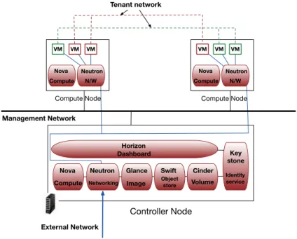
OpenStack is an open source cloud management system that allows tenants to pro-vision resources within specific limits set by the cloud administrator. Tenants can view, create and manage their resources either by a dedicated web graphical interface (Hori-zon) or through command line clients that interact with each one of OpenStack’s services. OpenStack operates in a fully centralized manner with one node acting as a controller. The controller accepts user VM life cycle commands and delegates them to a pool of compute nodes. Upon receiving a command from the cloud controller, a compute node enforces it by interacting with the hypervisor. The controller node hosts a plethora of the main services delivered by OpenStack such as: Nova (manager of the VMs lifecycle), Neutron (network connectivity manager), Glance (VM disk image manager) and Keystone (mapping of tenants to services that they can access). Nova and Neutron are also installed on each compute node in order to provide VM interconnectivity and enforce user decision regarding VMs lifecycle. Compute nodes periodically report back to the cloud controller
their available resources (processing, memory, storage) and the state of the deployed VMs (e.g. network connectivity, lifecycle events). OpenStack offers a limited set of integra-tion tools for other public APIs (namely Amazon EC2 and Google Compute Engine). A representation of OpenStack’s modular architecture can be found in Figure 2.2.
Controller Node
Nova Neutron Glance Swift Cinder Compute Networking Image Objectstore Volume
Horizon Dashboard Key stone Identity service Nova Compute Neutron N/W VM VM VM Nova Compute Neutron N/W VM VM VM Tenant network
Compute Node Compute Node
Management Network
External Network
Figure 2.2 – The OpenStack architecture
2.2.4 Deployment Models
There are four distinguishable cloud deployment models: Private, Public, Community and Hybrid clouds.
• Private cloud : The cloud infrastructure is deployed on compute, storage and network systems that belong to a single organization. A private cloud can be managed either by the organization or a third party entity and its usage does not exceed the scope of the organization.
• Public cloud : The cloud infrastructure is available for provisioning for everyone on the Internet. It is typically owned and managed by a cloud provider that allows customers (tenants) to request resources without having to deal with the burden of managing them. As a result tenants are only charged for what they use, in accordance with the pay-as-you-go model.
• Community cloud : The cloud infrastructure is dedicated to a specific community or organizations that share a set of policies (i.e. security concerns, mission, and compliance requirements). Community cloud comes as a solution for distributing costs between different organizations in contrast to each organization maintaining its own private cloud (e.g. scientists from different organizations that work on the same project can use the same community cloud). In contrast to public clouds access to community clouds is restricted only to members of the community or organization. They can be managed by one or several organizations of the community. Community clouds can be perceived as a specific category of private clouds.
• Hybrid cloud : The cloud infrastructure is a combination of two or more separate cloud infrastructures (private, public or community) that remain individual entities. The entities are bound together by a standardized agreement that allows data and application sharing.
In this thesis we developed a prototype considering a private cloud although the pro-posed framework can be integrated in both public and community clouds as well.
2.2.5 Dynamic Events in Iaas Clouds and Cloud Adaptation
Cloud environments are based on an elastic, highly scalable model that allows tenants to provision resources (e.g. VMs) with unprecedented ease. Furthermore tenants can choose to deploy different services inside their provisioned VMs and expose them to other users through the Internet, generating network traffic towards and from the cloud infrastructure. As a result, cloud environments become very dynamic, with frequent changes occuring at different levels of the infrastructure. In this section we categorize the observed changes in three categories: service-related, topology-related and traffic-related events.
2.2.5.1 Service-related Events
Service-related dynamic events include all changes in the applications deployed in the VMs of a single tenant. These changes can refer to addition (i.e. installation) of a new applica-tion or the removal of an existing one inside an already deployed VM. A reconfiguraapplica-tion of an existing application resulting in additional features is also considered a service-related dynamic event.
2.2.5.2 Topology-related Events
Topology-related events include all changes in the topology of a tenant’s virtual infras-tructure. The three main commands in a VM life cycle that constitute topology related dynamic events are: VM creation, VM deletion and VM migration (seamlessly moving a VM between two physical nodes over local or wide area network). VM migration can be interpreted as a combination of creation and deletion as when a VM is migrated between two nodes a new copy of the VM is created in the destination node, while the old copy of the VM is deleted from the source node. Public cloud providers offer the possibility of auto-scaling to their tenants in order to automate management of their application’s computational load. Scaling decisions generate topology-related changes either by adding new virtual machines (scaling out) or by deleting existing ones when the application’s load decreases (scaling in). Network reconfiguration events (e.g. changing a subnet’s ad-dress range, moving VMs between different subnets or creating/deleting subnets) are also considered topology-related changes.
2.2.5.3 Traffic-related Events
Often tenants deploy network-oriented applications in their cloud infrastructure. Depend-ing on the load of the deployed applications, different levels of network traffic are generated towards and from the virtual infrastructure. Any change in the tenant’s virtual infrastruc-ture incoming or outgoing traffic load is considered a traffic-related dynamic event. Public cloud providers offer load-balancing solutions in order to handle the dynamic network load and evenly distribute it to available resources. Load balancing decisions can also lead to topology-related changes when new VMs are started or shutdown.
2.2.5.4 Summary
In this section, we described the three main categories of dynamic events that occur in a cloud infrastructure. The security monitoring framework designed in this thesis addresses the need for reconfiguration of monitoring devices in all three event categories. We now continue with a description of virtualization technologies as the building block that enables cloud-computing.
2.3
Virtualization
This section gives a brief overview of infrastructure virtualization. Infrastructure virtu-alization can be decomposed in server virtuvirtu-alization and network virtuvirtu-alization. We first present the main server virtualization components followed by the four dominant server virtualization techniques. Finally, this section concludes with a description of network virtualization.
The first ones to define the notion of server virtualization where Popek and Goldberg in their paper ”Formal requirements for virtualizable third generation architectures” [33]. According to [33], virtualization is a mechanism permitting the creation of Virtual Ma-chines which are essentially efficient, isolated duplicates of real maMa-chines.
2.3.1 Server Virtualization Components
In an IaaS infrastructure there are three main architectural layers: physical, hypervisor and virtual machine. We briefly describe each one:
• Physical : The physical machine provides the computational resources that are di-vided between virtual machines (VMs). Computational resources include CPUs, memory and devices (e.g. disk, NIC).
• Hypervisor : Originally known as the Virtual Machine Monitor, this component is responsible for mediating the sharing of physical resources (e.g. CPU, memory) be-tween different co-located VMs that operate concurrently. The hypervisor is respon-sible for ensuring isolation between different VMs providing a dedicated environment for each one without impacting the others.
• Virtual Machine: A VM or guest is the workload running on top of the hypervisor. The VM is responsible for executing user applications and virtual appliances. Each VM is under the illusion that it is an autonomous unit with its own dedicated physical resources. The VM is oblivious about the existence of multiple other consolidated VMs on top of the hypervisor of the same physical machine.
The security monitoring framework designed in this thesis targets the virtual machine layer. For extracting key information regarding the services hosted inside the monitored VMs the hypervisor is leveraged.
2.3.2 Server Virtualization
There are different mechanisms that enable the creation of virtual machines each one pro-viding different features. Here we detail the four main ones: emulation, full virtualization, paravirtualization and OS-level virtualization. The contributions presented in this thesis apply to full virtualization and paravirtualization.
2.3.2.1 Machine-Level Virtualization
2.3.2.1.1 Emulation Emulation is the first proposed technique to allow the system to run a software that mimics a specific set of physical resources. This mechanism was used to enable the usage of console video games on personal desktop machines. In emulation, the assembly code of the guest is translated into host instructions, a technique known as binary translation. A dedicated component, the emulator is responsible for performing the translation and providing isolation between different guests. There are two different translation techniques: static and dynamic. Static binary translation requires translating all of the guest code into host code without executing it. Dynamic binary translation on the other hand offers at runtime emulation where emulators fetch, decode and execute guest instructions in a loop. The main advantage of dynamic binary translation is that since the translation is happening on the fly, it can deal with self-modifying code. Although the performance cost is evident, emulation is very flexible as any hardware can be emulated for a guest’s OS. Popular emulators include Bochs [34] and Qemu [35], which support a wide number of guest architectures (x86, x86 64, MIPS, ARM, SPARC).
2.3.2.1.2 Full Virtualization Full system-wide virtualization delivers a virtual ma-chine with dedicated virtual devices, virtual processors and virtual memory. In full vir-tualization the hypervisor is responsible for providing isolation between VMs as well as multiplexing on the hardware resources. This technique enables running VMs on top of physical hosts without the need to perform any alterations on the VM or the host OS kernel. In [33] the authors formalize the full-virtualization challenge as defining a virtual machine monitor satisfying the following properties:
• Equivalence: The VM should be indistinguishable from the underlying hardware. • Resource control: The VM should be in complete control of any virtualized resources. • Efficiency: Most VM instructions should be executed directly on the underlying CPU
without involving the hypervisor.
The two methods that make full virtualization possible are: binary translation and hardware acceleration. We discuss both of them.
Binary translation: This technique uses the native OS I/O device support while
offering close to native CPU performance by executing as many CPU instructions as pos-sible on bare hardware [36]. When installed, a driver is loaded in the host OS kernel in order to allow it’s user space component to gain access to the physical hardware when required. The same driver is responsible for improving network performance for the vir-tualized guest.Non-virvir-tualized instructions are detected using binary translation and are replaced with new instructions that have the desired effect on the virtualized hardware. The main argument behind virtualization through binary translation is that no modifi-cations of either the guest or the host OS are required. Unfortunately, a non-negligible performance penalty is applied due to the need of performing binary translation and em-ulation of privileged CPU instructions. Full virtualization with binary translation can be interpreted as a hybrid technique between emulation and virtualization. In contrast to em-ulation where each CPU instruction is emulated, full virtualization with binary translation allows for some CPU instructions to run directly on the hosts CPU. The most popular fully virtualized solutions using binary translation are: Qemu [35], VirtualBox [37], VMware Fusion and Workstation [38] [39].
Hardware acceleration: In order to cope with the performance overhead intro-duced by binary translation and enable virtualization of physical hardware, Intel (resp. AMD) came up with the VT-x technology [40] (resp. AMD-V). With VT-x a new root mode of operation is allowed in the CPU. Two new transitions are enabled: from the VMM to a guest a root to non-root transition (called VMEntry) and from the guest to VMM a non-root to root transition (called VMExit). Intel uses a new data structure to store and manage information regarding when these transitions should be triggered, the virtual machine control structure (VMCS). Typically a VMExit occurs when the VM attempts to run a subset of privileged instructions. The VMCS data structure stores all necessary information (instruction name, exit reason). This information is later used by the VMM for executing the privileged instruction. The most popular solutions using hardware as-sisted virtualization are: KVM [27], VMware ESXi [29], Microsoft Hyper-V [41] and Xen Hardware Virtual Machine [42].
2.3.2.1.3 Paravirtualization In contrast to full virtualization which advocates for
no modifications in the guest OS, paravirtualization requires the guest OS kernel to be modified in order to replace non-virtualized instructions with hypercalls that communi-cate directly with the hypervisor. The hypervisor is responsible for exporting hypercall interfaces for other sensitive kernel operations such as memory management and inter-rupt handling. Xen Project [28] has been the most prominent paravirualization solution. In Xen the processor and memory are virtualised using a modified Linux kernel. The modified kernel is actually an administrative VM (called dom0) responsible for providing isolation between VMs, handling network, I/O and memory management for the guest VMs (domU). Dom0 is also in control of the guest VMs lifecycle and bares the responsi-bility for executing privileged instructions on behalf of the guest OS. The later is done by issuing hypercalls. Dom0 traps the latter and executes them either by translating them to native hardware instructions or using emulation. Xen operates based on a split driver model where the actual device drivers, called backend drivers, are located inside Dom0 and each DomU implements an emulated device, called frontend driver. Every time a DomU issues a call to a driver the emulated part transfers the call to the actual driver in Dom0 – hence the two drivers complementary operate as one. Although Xen is a promising solution for near native performance, its application is limited to open source OSes like Linux or proprietary solutions which offer a customized Xen-compatible version.
2.3.2.1.4 Hypervisor Practices Emulation, full virtualization and
paravirtualiza-tion can be combined. Typically, devices are fully emulated (for maintaining the use of legacy drivers) or paravirtulized (for efficient multiplexing access on these devices from different VMs) while the CPU is fully virtualized. Modern hypervisors that adopt this technique are: KVM [27], Xen [28] and VMware Workstation [39].
2.3.2.2 OS-level Virtualization
Another solution, known as lightweight or OS-level virtualization [43], allows the OS kernel to perform virtualization at the system call interface, and create isolated environments that share the same kernel. These flexible, user-oriented isolated environments are known as containers. Containers have their own resources (e.g. file system, network connectivity, firewall, users, applications) that are managed by the shared OS kernel (responsible for providing isolation). Since they all share the same kernel the performance overhead is minimal to none. Furthermore, a container can be migrated in the same way as a VM.
Unfortunately, the main issue behind OS-level virtualization is that all containers in a single physical machine are limited to the kernel of the host OS. This limits the number of OSes to only the ones supported by the host’s kernel. LXC [44] and Docker [45] are some of the most prominent solutions in this category.
2.3.3 Network Virtualization and Network Management in IaaS Clouds
Network virtualization is one of the key aspects in an IaaS cloud environment. Assigning IP addresses to VMs, communication between VMs that belong to the same or different tenants and finally communication between VMs and the outside world are some of the issues that need to be addressed from the network virtualization component of the IaaS cloud management system. In this section we first present the mechanisms that materialize network virtualization and we continue with a discussion about network management in IaaS clouds focusing on OpenStack.
2.3.3.1 Network Virtualization
There are different solutions that enable network virtualization. Multi-protocol Label Switching [46] uses a ”label” appended to a packet in order to transport data instead of using addresses. MPLS allows switches and other network devices to route packets based on a simplified label (as opposed to a long IP address). Hard VLANs allow a single physical network to be broken to multiple segments. By grouping hosts that are likely to communicate with each other to the same VLAN, one can reduce the amount of traffic that needs to be routed. Flat networking relies on the ethernet adapter of each compute node (which is configured as a bridge) in order to communicate with other hosts. With VLAN tagging each packet belonging to a specific VLAN is assigned the same VLAN ID while with GRE encapsulation traffic is encapsulated with a unique tunnel ID per network (the tunnel ID is used in order to differentiate between networks). VLAN tagging and GRE encapsulation both require a virtual switch in order to perform the tagging (respectively encapsulation) while flat networking does not require a virtual switch.
However these solutions lack a single unifying abstraction that can be leveraged to
configure the network in a global manner. A solution to this empedement that
pro-vides dynamic centrally-controlled network management is software defined networking (SDN) [47]. In this section we mainly focus on SDN.
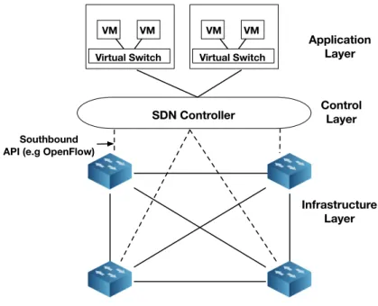
Software defined networking [47] emerged as a paradigm in an effort to break the vertical integration of the control and the data plane in a network. It separates a network’s control logic from the underlying physical routers and switches which are now simple forwarding devices. The control logic is implemented in a centralized controller allowing for a more simplified policy enforcement and network reconfiguration. Although SDNs are logically centralized, the need for a scalable, reliable solution that guarantees adequate performance does not allow for a physically centralized approach. The separation between the control and the data plane is feasible by creating a strictly defined programmable interface (API) between the switches and the SDN controller. The most notable example of such API is OpenFlow [48]. In each OpenFlow switch flow tables of packet-handling rules are stored. Each rule matches a subset of the traffic and performs certain actions (dropping, forwarding, modifying) on the matched subset. The rules are installed on the switches by the controller and depending on their content a switch can behave like a router, switch, firewall or in general a middlebox. A switch can communicate with the controller through a secure channel using the OpenFlow protocol which defines the set of messages that can be exchanged between these two entities. Traffic handling rules can be installed
on the switches either proactively or reactively, when a packet arrives. A representation of the SDN architecture can be found in Figure2.3.
SDN Controller Infrastructure Layer Control Layer Application Layer Southbound API (e.g OpenFlow)
Virtual Switch VM VM
Virtual Switch VM VM
Figure 2.3 – The SDN architecture
Although OpenFlow is the most widely accepted and deployed API for SDNs there are several other solutions such as ForCES [49] and POF [50]. The controller provides a programmatic interface to the network that can be used to execute management tasks as well as offer new functionalities. It essentially enables the SDN model to be applied on a wide range of hardware devices (e.g. wireless, wired). A wide range of available controllers exist such as Nox [51], OpenDaylight [52] and Floodlight [53].
Making network virtualization a consolidated technology requires multiple logical net-works to be able to share the same OpenFlow networking infrastructure. FlowVisor [54] was one of the early solutions towards that direction. It enables slicing a data plane based on off-the-shelf OpenFlow compatible switches, making the coexistence of multiple net-works possible. The authors propose five slicing dimensions: bandwidth, topology, traffic, forwarding tables and device CPU. Each slice can have its own controller allowing multiple controllers to inhabit the same physical infrastructure. Each controller can only operate on its own slice and gets its own flow tables in the switches.
FlowN [55] offers a solution analogous to container virtualization (i.e. a lightweight virtualization approach). In contrast with FlowVisor [54], it deploys a unique shared controller platform that can be used to manage multiple domains in a cloud environment. A single shared controller platform enables management of different network domains. It offers complete control over a virtual network to each tenant and it allows them to develop any application on top of the shared controller.
Network virtualization platform (NVP) from VMware (as part of the NSX [56] prod-uct) provides the necessary abstractions for the creation of independent networks (each one with different service model and topology). No knowledge about the underlying net-work topology or state of the forwarding devices is required as tenants simply provide their desired network configuration (e.g. addressing architecture). NVP is responsible for translating tenant requirements to low-level instruction sets that are later on installed on the forwarding devices. A cluster of SDN controllers is used in order to modify the
flow tables on the switches. NVP was designed to address challenges in large-scale multi-tenant environments that are not supported by the previously described solutions (e.g. migrating an information system to the cloud without the need of modifying the network configuration). A similar solution is SDN VE [57] from IBM based on OpenDaylight.
2.3.3.2 Network Management in Iaas Clouds
Network virtualization delivers compute-related options (create, delete) to network man-agement. Network objects (networks, subnets, ports, routers, etc) can be created, deleted and reconfigured programmatically without the need of reconfiguring the underlying hard-ware infrastructure. The underlying hardhard-ware infrastructure is treated as a pool of trans-port resources that can be consumed on demand. Tenants can create private networks (i.e. tenant networks) and choose their own IP address scheme, which can overlap with IP addresses chosen by other tenants. Depending on the type of the tenant network (flat, VLAN, GRE) different communication capabilities are offered to the instances attached to these networks.
The networking component of an IaaS cloud management system is responsible for mapping tenant-defined network concepts to existing physical networks in a data cen-ter. Essentially the network component performs the following functionalities: assign IP addresses to VMs, facilitating communication between VMs that belong to the same or different tenants and finally providing VMs with outside-world connectivity.
In OpenStack, Neutron is responsible for managing different tenant networks and offer-ing a full set of networkoffer-ing services (routoffer-ing, switchoffer-ing, load-balancoffer-ing, etc) to provisioned VMs. Neutron is composed of agents (e.g. DHCP agent, L3 routing agent, etc) that pro-vide different types of networking services to provisioned VMs. Neutron creates three different networks in a standard cloud deployment:
1. Management network: used for communication between the OpenStack components. This network is only reached from within the datacenter.
2. Tenant networks: used for communication between VMs in the cloud. The config-uration of these networks depends on the networking choices made by the different tenants.
3. External network: used to provide internet connectivity to VMs hosted in the cloud. On each compute node a virtual bridge is created by a dedicated Neutron plugin (called ML2 plugin) which is locally installed on each node. VMs are connected to networks through virtual ports on the ML2-created bridge. The ML2 plugin is also responsible for segregating network traffic between VMs on a per tenant basis. This can be achieved either through VLAN tagging (all VMs that belong to the same network are assigned the same tag) or GRE encapsulation.
2.4
Security Threats
In this section we detail some of the known attacks against information systems and cloud environments.
2.4.1 Security Threats in Information Systems
Although one of the most common ways of executing cyber attacks is through the network (i.e. either the Internet or a local area network), the attackers often target different areas
in an information system. Here we list the most common threats depending on their target level. Before presenting each threat category in detail, we present a high level overview of the vulnerability classes that attackers can exploit. In general, missing validation of inputs in an application can create an entry point for attacks (listed below). Furthermore, lack of access control (i.e. through authentication mechanisms) can allow an attacker to gain unauthorized privileged access.
2.4.1.1 Application Level
Application-level threats are abilities of an attacker to exploit vulnerabilities in the soft-ware of one or more applications running in an information system.
One of the most common application-level attack is SQL injection [58] against Database Management Systems (DBMS). An SQL injection attack occurs when a malicious entity on the client side manages to insert an SQL query via input data to the application. This is usually possible due to lacks of input validation. The impact of the injection may vary depending on the skills and imagination of the attacker. Usually, through an SQL exploit the attacker can gain access to sensitive data inside the database, modify them (insert or delete or update) or even retrieve the contents of a file present in the system. He can also shutdown the DBMS by issuing administrative commands and sometimes even execute commands outside the DBMS.
Another type of an injection attack is cross-site scripting (XSS) [59] when the attacker manages to insert malicious code in a trusted website. Cross-site scripting exploits the absence of validation of user input. The malicious code could be in the form of a JavaScript segment or any other code that the browser can execute. When a different user accesses this website she will execute the script thinking that it comes from a trusted source, giving the attacker access to cookies, session tokens or other sensitive information retrieved by the browser on behalf of the infected website. In a more severe scenario the attacker might even redirect the end user to web content under his control. An XSS attack can either be stored (the malicious script permanently resides on the target server) or reflected (the script is reflected off the web server – for example in an error message).
A buffer overflow [60] generally occurs when an application attempts to store data in a buffer and the stored data exceeds the buffer’s limits. Buffer overflows are possible because of badly validated input on the application’s side. Writing in an unauthorized part of the memory might lead to corrupted data, application crashes or even malicious code execution. Buffer overflows are often used as entry points for the attacker in order to inject malicious code segment into the host’s memory and then execute it by jumping to the right memory address. Another alternative for malicious code injection is format string attacks [61]. Format String Attacks (FSA) are used in order to leak information such as pointer addresses. After a successful FSA, normally a return oriented programming exploit is used. Return oriented programming allows the attacker to use short sequences of instructions that already exist in a target program in order to introduce arbitrary behavior.
2.4.1.2 Network Level
In the network-level threat category we describe attacks that target communications of layer 3 and above in an information system.
Network-level impersonation occurs when an attacker masks his true identity or tries to impersonate another computer in network communications. Operating systems use the IP address of a packet to validate its source. An attacker can create an IP packet with a header that contains a false sender’s address, a technique known as IP spoofing [62].