HAL Id: hal-01858138
https://hal-mines-albi.archives-ouvertes.fr/hal-01858138
Submitted on 5 Sep 2018HAL is a multi-disciplinary open access archive for the deposit and dissemination of sci-entific research documents, whether they are pub-lished or not. The documents may come from teaching and research institutions in France or abroad, or from public or private research centers.
L’archive ouverte pluridisciplinaire HAL, est destinée au dépôt et à la diffusion de documents scientifiques de niveau recherche, publiés ou non, émanant des établissements d’enseignement et de recherche français ou étrangers, des laboratoires publics ou privés.
A transparent micro-device to study mass transfer and
thermodynamics in two-phase flows at high pressure
Thomas Deleau, Jean-jacques Letourneau, Séverine Camy, Fabienne
Espitalier, Hugo Helouvry, Joelle Aubin, Nayane Macedo Portela da Silva
To cite this version:
Thomas Deleau, Jean-jacques Letourneau, Séverine Camy, Fabienne Espitalier, Hugo Helouvry, et al.. A transparent micro-device to study mass transfer and thermodynamics in two-phase flows at high pressure. 12th International Symposium on Supercritical Fluids, INTERNATIONAL SOCIETY FOR THE ADVANCEMENT OF SUPERCRITICAL FLUIDS, Apr 2018, Antibes-Juan-Les-Pins, France. 8 p. �hal-01858138�
PQ02
A transparent micro-device to study mass transfer and
thermodynamics in two-phase flows at high pressure
T. Deleau* a, J-J. Letourneau a, S. Camy b, F. Espitalier a, J. Aubin b, H. Helouvry a, N. Macedo Portela da Silva a
aUniversité de Toulouse, Mines Albi, CNRS UMR 5302
École des Mines d'Albi, Centre RAPSODEE, Campus Jarlard, 81013 ALBI
b Laboratoire de Génie Chimique, Université de Toulouse, CNRS, INPT, UPS, 4 Allée Emile Monso, 31030
TOULOUSE
ABSTRACT
Concentration data and mass transfer coefficients between supercritical CO2 and water in
microfluidic capillaries are still scarce in the literature, although they are a big asset for the understanding of green chemical processes using water and supercritical CO2.
In this study, a transparent, inexpensive and pressure resistant microsystem is developed to investigate mass transfer of a two-phase flow of water and CO2 under high-pressure (P > 70
bar). It is based on microcapillary technology [1] and allows 2D axisymmetric modelling.
INTRODUCTION
Since the early 1980s, microfluidics has proven to be an effective means to intensify chemical processes. Indeed, the decrease in characteristic length scales leads to shorter diffusional paths increased surface area to volume ratios, thereby decreasing the characteristic times for heat and mass transfer and enhancing transport phenomena. With the emergence of high-pressure applications in microfluidics, the development of highly resistant microfluidic chips has been the focus of a number of studies. Amongst these, glass/glass [2] and silicon/glass microreactors [3-5] have shown to resist pressures of up to 400 bar. The microchannels are constructed using either wet or dry etching methods and then are sealed to glass via anodic bonding. These microchips have the advantage of resisting high-pressures and also allow optical access to the flow for in-situ characterization. In addition, silicon/glass chips have the asset of enabling very good temperature control due to the high thermal conductivity of the silicon wafer [5]. However, the fabrication methods employed require clean room facilities, specific equipment and expertise, and entail relatively high operating and fabrication costs, which are limiting when rapid prototyping is required. Some simpler glass devices based on fused-silica capillaries have also been proposed for high-pressure applications [1, 6]. Marre et al. [6] showed the use of silica capillaries under pressure conditions ranging from 80-180 bar. Macedo Portela da Silva et al. [1] demonstrated that operating pressures up to 300 bar could be achieved by embedding silicon capillaries in epoxy resin. Both of these studies also showed that two-phase flow can be easily visualized and characterized by shadowgraphy in such capillaries. However more elaborate optical characterization techniques, such as micro Particle Image Velocimetry, would be limited in these devices because of problems related to optical distortion, poor light transmission and focal depth. Recently, Martin et al. [7] developed systems based on the use
UV-curable off-stoichiometry thiol-ene epoxy (OSTE+) polymer chemically bonded to glass that proved to be resistant to CO2 without failure up to at least 200 bar and could be used at
high pressure for several hours. However, such devices are up to now limited in terms of channel size and lengths. The purpose of this study is to develop capillary-based microfluidic devices, which are reinforced by the use of UV-curable off-stoichiometry thiol-ene epoxy (OSTE+) polymer and allow sufficient channel lengths in order to investigate mass transfer occurring in a two-phase CO2-water system.
MATERIALS AND METHODS 2.1 Microreactor design
The microreactor developed in this study (Figure I(a)) is based on the pressure-resistant microreactor technology developed by [1] and [7], whereby a capillary tubing is embedded in a transparent resin and supported by a polymethyl methacrylate (PMMA) chassis. In this new prototype OSTEMER resin, which has high optical quality and has shown to be resistant to pressure [7], is used for embedding the capillary tubes and ensuring optical access to the flow via a glass window.
The dimensions of the microreactor and the different elements, i.e. chassis, resin, and glass window, are shown in Figure I(b).
(a) (b)
Figure I. (a) Schematic diagram of the microreactor with lighting system; (b) dimensions of the reactor with the
40mm x 40 mm viewing window and guide supports (dark blue).
2.2 Fabrication
A PMMA block (270 x 140 x 20 mm3) is machined with a digital milling machine (Charlyrobot
– Charly4U CNR3) to order to hold a glass window (40mm x 40mm) and house the coiled capillary system. A transparent box is also made in order to contain the reactor and a heating fluid. The milling process takes approximately 4 hours.
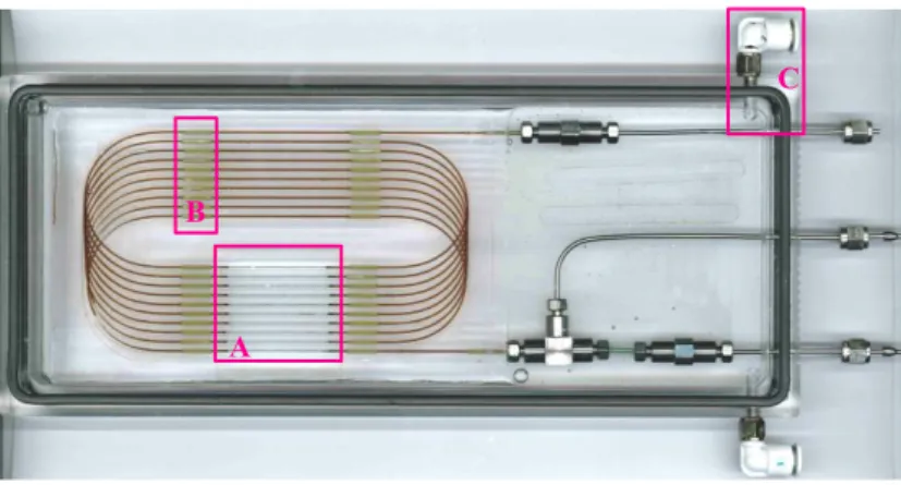
3 m of fused-silica capillary tubing (ID = 530 µm and OD = 665 µm) is coiled and inserted into the chassis and held in place with a guiding support, in which sleeves are inserted (region B in
figure II). The plastic coating around the capillary is then carefully burned using a flame and removed with a cotton swab under a microscope in order to improve the optical transparency of the observation zone (region A in figure II).
OSTEMER resin (Mercene Labs) is then poured over the top of the capillary system into the PMMA/glass support, such that it entire covers the capillary tubes. The ensemble is then exposed to UV light for 35 s at 25 mW/cm2.Crystal Clear OSTEMER resin has been chosen
because of its transparency and low shrinkage properties as reported by Martin et al. [7]. Stainless-steel connectors for high pressure applications (Upchurch Scientific, USA) are used to connect the capillary reactor to the external network pipes (pumps etc.). Two phase flow is generated in the capillary using a coaxial contacting setup with a T-junction.
Figure II. The transparent high pressure micro-reactor.
2.3 Experimental rig
The microreactor is integrated into a high-pressure circuit, which is fed by two syringe pumps (ISCO 260 ISCO 100 D and HLX) to reach pressures up to 20 MPa. The pumps are filled with water and with CO2 (purity 99.995%; Linde, France), and control the volume flow rates
(approximately 10-2 mL.min-1) and the fluids temperature (20°C for water and 5°C for CO 2). A
third syringe pump (ISCO 260 D) is placed at the outlet of the microreactor output in order to maintain and control the output pressure in the system (up to 20 MPa). The microreactor is put into a transparent box and immerged in a circulating heat transfer fluid in ordain to maintain a constant temperature in the reactor. The box has been setup to force the fluid circulation everywhere around the micro-reactor. Inlet/outlet for this heat transfer fluid is shown in figure II (region C).
A Coriolis-type micro-flowmeter is used to control CO2 mass flowrate at the microreactor inlet.
Indeed, the mass flowrate is not so easy to control because of CO2 temperature change between
the pump and the microreactor inlet which involves density change. Furthermore, the pressure change affects a lot fluid properties.
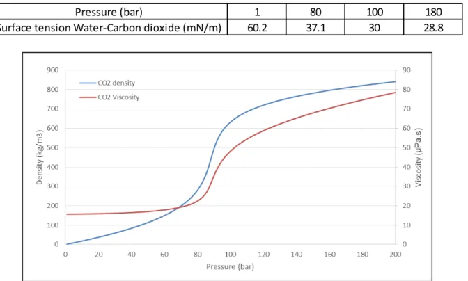
Figure III shows in what extend the density [9], viscosity [10] and surface tension of CO2 [11]
vary between atmospheric pressure and 200 bar. These changes of properties have to be taken into account to understand behaviour of fluid phase in the different parts of the experimental set-up (pump, tubing, microsystem).
A B
Table 1: Values of surface tension between water and CO2 for different pressures.
Figure III. Fluid properties of CO2 changing with pressure.
Formation of the flow can be recorded by a CCD camera (Baumer HXC13) with a resolution of 1280 x 1021 pixels2. The videos can be acquired at 2000 frames per second. The microchannel is lit with LED lamps that have a light intensity of 2200 lumen. As an example, Figure IV, reports a photo of a stable two-phase Taylor flows of CO2 and water obtained at 20
MPa using a microcapillary set-up identical to the one described in [1]. Optical access to the flow makes it possible to quantify the volume change of bubbles (due mass transfer between the gas and the liquid phases).
Figure IV. P = 20 MPa; T=308 K; VCO2= 0.02 mL.min-1; VH2O= 0.02 mL.min-1 in a 530 µm capillary.
The main advantage of this kind of device is the high pressure resistance, ease of fabrication and rather low price, with the “T” and “U” junctions that can be recovered after reactor failure (the lifetime of micro-reactors is not infinite due to the high pressure use).
Other advantages for hydrodynamics and mass transfer investigations lie in the circular cross section (creating an axial symmetrical system and makes CFD simulations and modelling easier), the coiling system that allows a reactor up to 10 meters long and an inner surface that is perfectly smooth.
Pressure (bar) 1 80 100 180
Moreover, the cylindrical fused-silica tubing (Polymicro, USA) is coated with polyimide cladding as a protection and provides a great flexibility. When the coating is removed, the capillary is completely transparent which allows an optical access.
Finally, it should be pointed out that attention was paid to curvature effects. Indeed, curvature effects can lead to flow instabilities or to coalescence of the dispersed phase and can even be used to separate phases. For this device, the Bond number Bo = Δ𝜌 𝑎 𝐿 /𝜎 with 𝑎 = 𝑣/𝑅 , is calculated with centrifugal acceleration. Considering identical mixtures, with identical operating conditions and with the same channel surface sections, the Bond number of the on-chip microdevices (bending radius 𝑅 = 0.3 mm) is 100 times higher than of the presented device (bending radius = 30 mm).
A few disadvantages still remain on this device: the only possible kind of entry is a coaxial one. The effect of a T-junction on high pressure can’t be investigate as carried out in Yao et al. [8]. Moreover, the current system of temperature regulation does not allow a spectroscopic access such as Raman spectroscopy some technical solutions are presently under investigations (heating film, warm air box…).
CONCLUSION AND FUTURE WORK
This work describes the fabrication of a microreactor that is able to resist pressures up to 20MPa and suitable for the use of high-pressure CO2. The target of such a device is to use it to
investigate mass transfer between gaseous CO2 and an aqueous liquid phase. The next step of
this work will consist in implementing optical techniques and/or spectroscopic techniques, which will enable concentrations of the different components to be measured along the microchannel. In combination with phenomenological modelling, this set-up will be used as a tool to calculate mass transfer coefficients between components at high pressure.
REFERENCES
[1] Macedo Portela da Silva, Nayane, Jean-Jacques Letourneau, Fabienne Espitalier, and Laurent Prat. « Transparent and Inexpensive Microfluidic Device for Two-Phase Flow Systems with High-Pressure Performance ». Chemical Engineering & Technology 37, no 11 (2014): 1929–1937.
[2] Tiggelaar RM, Benito-López F, Hermes DC, Rathgen H, Egberink RJM, Mugele FG, Reinhoudt DN, van den Berg A, Verboom W, Gardeniers HJGE (2007) Fabrication, mechanical testing and application of high-pressure glass microreactor chips. Chem Eng J 131:163–170. doi:10.1016/j.cej.2006.12.036
[3] Trachsel F, Hutter C, Vonrohr P (2008) Transparent silicon/glass microreactor for high-pressure and high-temperature reactions. Chem Eng J 135:S309–S316. doi:10.1016/j.cej.2007.07.049
[4] Murphy ER, Inoue T, Sahoo HR, Zaborenko N, Jensen KF (2007) Solder-based chip-to-tube and chip-to-chip packaging for microfluidic devices. Lab Chip 7:1309. doi:10.1039/b704804a
[5] Marre S, Adamo A, Basak S, Aymonier C, Jensen KF (2010) Design and packaging of microreactors for high pressure and high temperature applications. Ind Eng Chem Res 49:11310–11320. doi:10.1021/ie101346u
[6] Marre S, Aymonier C, Subra P, Mignard E (2009) Dripping to jetting transitions observed from supercritical fluid in liquid microcoflows. Appl Phys Lett 95:134105. doi:10.1063/1.3242375
[7] Martin Alexandre, Sébastien Teychené, Séverine Camy, et Joëlle Aubin. « Fast and Inexpensive Method for the Fabrication of Transparent Pressure-Resistant Microfluidic Chips ». Microfluidics and Nanofluidics 20, no 6 (1 juin 2016): 92.
[8] Yao, Chaoqun, Zhengya Dong, Yuchao Zhao, et Guangwen Chen. « The Effect of System Pressure on Gas-Liquid Slug Flow in a Microchannel ». AIChE Journal 60, no 3 (1 mars 2014): 1132-42. [9] Span, R,; Wagner, W,, A New Equation of State for Carbon Dioxide Covering the Fluid Region from the Triple-Point Temperature to 1100 K at Pressures up to 800 MPa, J, Phys, Chem, Ref, Data, 1996, 25, 6, 1509-1596.
[10] Fenghour, A.; Wakeham, W.A.; Vesovic, V., The Viscosity of Carbon Dioxide, J. Phys. Chem. Ref. Data, 1998, 27, 31-44.
[11] Georgiadis, Apostolos, Geoffrey Maitland, J. P. Martin Trusler, et Alexander Bismarck. « Interfacial Tension Measurements of the (H2O + CO2) System at Elevated Pressures and Temperatures ». Journal of Chemical & Engineering Data 55, no 10 (14 octobre 2010): 4168-75.