HAL Id: hal-01494934
https://hal.archives-ouvertes.fr/hal-01494934
Submitted on 24 Mar 2017HAL is a multi-disciplinary open access
archive for the deposit and dissemination of sci-entific research documents, whether they are pub-lished or not. The documents may come from teaching and research institutions in France or abroad, or from public or private research centers.
L’archive ouverte pluridisciplinaire HAL, est destinée au dépôt et à la diffusion de documents scientifiques de niveau recherche, publiés ou non, émanant des établissements d’enseignement et de recherche français ou étrangers, des laboratoires publics ou privés.
Evaluation of Currents Induced in Human Body by
Plane Wave Exposure At 1-90 MHz
Jeanne Frere, Alain Alcaras, Maxim Zhadobov, Christophe Lemoine, Gwenaël
Le Cadre, Ronan Sauleau
To cite this version:
Jeanne Frere, Alain Alcaras, Maxim Zhadobov, Christophe Lemoine, Gwenaël Le Cadre, et al.. Eval-uation of Currents Induced in Human Body by Plane Wave Exposure At 1-90 MHz. EuCAP 2017, Mar 2017, Paris, France. �hal-01494934�
Evaluation of Currents Induced in Human Body by
Plane Wave Exposure At 1-90 MHz
Jeanne Frere1,2, Alain Alcaras1, Maxim Zhadobov2, Christophe Lemoine2, Gwenaël Le Cadre1, Ronan Sauleau2 1 Thales Communications & Security, 110 avenue du Maréchal Leclerc, BP 70945, 49309 Cholet Cedex
2 IETR, UMR CNRS 6164, Université de Rennes 1, 263 avenue du Général Leclerc, 35042 Rennes
jeanne.frere@univ-rennes1.fr
Abstract—In existing exposure standards and guidelines the
relationship between dosimetric quantities at a given frequency is not always consistent as some simultaneously applied limits are more restrictive than others, e.g. limits on induced currents compared to those on external electric field or specific absorption rate (SAR). To evaluate the current induced in the human body in 1 – 90 MHz range, we propose an equivalent circuit composed of two elements: the first one provides the voltage at human body mid-height and the second one describes the equivalent human body impedance. Then, assuming that the human body is equivalent to an antenna between 1 and 90 MHz, we calculate induced currents at the human body height. Using the relationship between external electric field and voltage at the body mid-height, we calculate the current along the body and suggest updated limits on induced currents more consistent with the external electric field limits.
Index Terms—Human body equivalent impedance circuit,
induced currents, HF, VHF.
I. INTRODUCTION
Because of the increasing number of wireless systems, accurate dosimetric assessment of interactions between radio-frequency (RF) electromagnetic fields and human body is of importance. In the 1 - 90 MHz range the limits established by ICNIRP [1] and IEEE [2] are defined in terms of external electric and magnetic fields, induced currents, current density and specific absorption rate (SAR). Tofani et al. reported that some limits are not fully consistent with each other, in particular in 90 - 104 MHz range [3]. Although the limits on external electric field were not overpassed, the induced current exceeded the limits, which were the following: 45 mA for uncontrolled environment and 100 mA for controlled environment through one foot between 0.1 MHz and 100 MHz [4]. The same observation was made in a study by Gandhi et
al. where the limits on currents induced by plane wave
exposure up to 50 MHz were not overpassed although limits on SAR 1g were exceeded [5].
Several studies have used an equivalent antenna to model human body. Gandhi and Aslan have developed a human-equivalent antenna to measure the external current induced in a human body by RF exposure [6]. The antenna impedance was approximated by the human body impedance in 3 kHz – 110 MHz range. Using this antenna allows induced current measurements without human subject. In 2003, Poljak et al.
developed a human equivalent antenna model for transient electromagnetic exposure. They used thick cylindrical antennas to represent the human body and thin-wire approximation to evaluate the current induced in human body for a body exposed to a pulsed radiation between 50 Hz and 110 MHz [7]. Recently Kibret et al. characterized the human body as a monopole antenna from 10 MHz to 110 MHz [8]. They gave physical dimensions of the equivalent cylindrical antenna and characterized it experimentally (in terms of radiation efficiency, reflection coefficient and impedance).
The main objective of this work is to analyze theoretically the relationship between induced currents and incident electric fields in the 1 – 90 MHz frequency range. The actual limits of induced current for a controlled environment are used, i.e. 100 mA in one foot in 1 - 90 MHz range [2]. The human body is modeled as a thick dipole antenna to calculate induced currents from the external applied electric field for plane wave exposure. The coupling between the thick dipole and the incident plane wave is modeled using an equivalent Thevenin circuit consisted of a voltage source Vth and impedance Zth
(section III). This circuit allows calculating currents induced in the dipole. We validate the equivalent circuit by comparing induced currents computed in a realistic human body model with those calculated using the Thevenin circuit. Finally we use this equivalent circuit to suggest in the last section more consistent limits on induced currents in respect to the limits on external electric field.
II. MATERIALS AND METHODS
A. Anatomical human body model
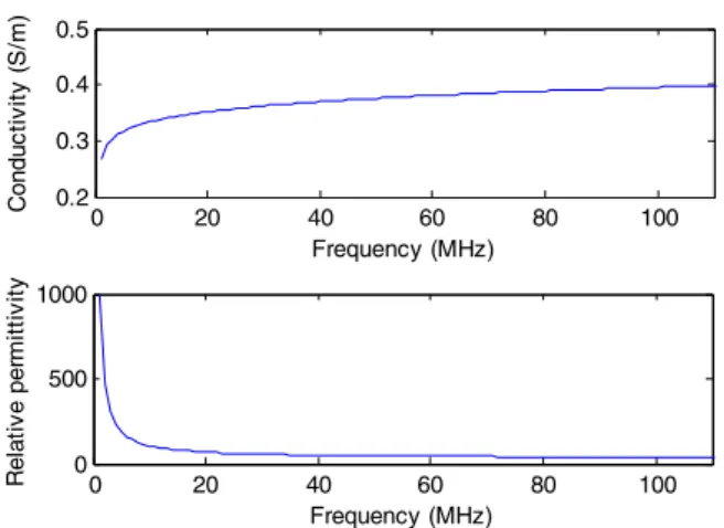
We used the anatomical voxel body model Duke from Virtual Family [9]. It is a 1.74 m high and 70 kg male model with a voxel size of 5 mm. In total 77 tissues are modeled in simulations. We used a heterogeneous and homogenized model with the same body geometry. For the heterogeneous phantom, the dielectric properties were taken from Gabriel database [10]. For the homogeneous one, the equivalent tissue mass density was set at 1025 kg/m3; its dispersive
electromagnetic properties (i.e. relative permittivity and conductivity) are represented in Fig. 1. These are weighted average of the nine most present tissues from Hugo model of the Visible Human [11].
0 20 40 60 80 100 0.2 0.3 0.4 0.5 C o n d u c ti vi ty ( S /m ) Frequency (MHz) 0 20 40 60 80 100 0 500 1000 R e la ti ve p e rm it ti vi ty Frequency (MHz)
Fig. 1. Electromagnetic properties of the equivalent tissue used to homogenize Duke phantom
B. Numerical modeling
The phantom is exposed to a vertically polarized plane wave in the frequency range 1-90 MHz with E rms field of 61 V/m. The numerical problems are solved using finite integration technique implemented in CST Microwave Studio. Matlab is used to calculate the induced current solving the Thevenin equivalent circuit.
III. HUMAN-EQUIVALENT IMPEDANCE AND VOLTAGE CIRCUIT
In this section, based on the standard Thevenin equivalent circuit (Fig. 2), we develop a circuit equivalent to human body for a vertically polarized plane wave exposure between 1 and 90 MHz in free space. The circuit is composed of two elements. The first element is the Thevenin voltage Vth that
evaluates the voltage source at mid-height of the phantom equivalent to the coupling with the external applied electric field (Eext). The second element is the Thevenin impedance Zth
that evaluates the human equivalent antenna impedance. We assume that human body is conductive enough (i.e. σ > ωε0εr
in the considered frequency range) to consider it as equivalent to a homogeneous thick dipole antenna to design our circuits. The load in Fig. 2 is set as a short circuit. Then with this circuit, we calculate induced current at mid-height of the phantom.
A. Electric model of Thevenin voltage Vth
The voltage at mid-height of the dipole antenna is the equivalent Thevenin voltage Vth and it depends on the antenna
effective height. Therefore to design the voltage Vth in circuit,
we have determined the effective height of Duke phantom depending on its physical parameters and frequency.
For frequencies below the Duke phantom resonance (i.e. f < 65 MHz), the effective height of the antenna is H/2 where H is the height of the antenna equal to the physical height of the Duke phantom. At resonance, the effective height is assumed to be λ/2 where λ is the wavelength in vacuum.
Fig. 2. Thevenin equivalent circuit modeling the voltage and impedance at mid-height of the phantom Duke
Between 65 MHz and 200 MHz we assume that the effective height decreases with a -40 dB/decade slope. Therefore we can represent the voltage behavior in the thick dipole (i.e. in the phantom Duke) by a 2nd order low-pass filter. V
th is described by 2 2 1 1 1 1 0 0 1 1 2 ext ext th E E V jR C L C jmωω ωω ω ω = = + − + + (1)
where Eext is the rms external electric field, ω = 2πf the angular
frequency, ω0 the angular frequency at resonance and m the
damping factor, R1, C1 and L1 are the resistance, capacitor and
inductance representing the lumped elements in the electric model of Vth.
The voltage below and at resonance is defined by (2) and (3), respectively. 2 th H ext V = E (2) 2 th ext V =λ E (3)
After simulating the Thevenin voltage of Duke from 1 MHz to 300 MHz (Fig. 4a), we set the damping factor m = 0.35 and resistance R1 = 100 Ω. Because the resonance
frequency appears for H ~ λ/2, we can deduce R and C from equations (4) and (5). The electric model of Vth is described by
Fig. 3a where R1 = 100 Ω, L1 = 265 nH, C1 = 13 pF and the
source generator V2 is the external rms electric field Eext of the
planewave. 0 1 1 1 L C ω = (4) 1 1 1 2 R C m L = (5)
As the dipole is thick, we have introduced a corrective factor of 0.74 to take into account the antenna thickness (shortening factor [12]). Therefore the voltage at mid-height of the phantom is given by
2 1 1 1 1 0.74 1 ext th E V jR Cω L Cω = + − (6)
B. Electric model of human antenna impedance
To design the electric model of the Thevenin impedance (equivalent to human body impedance), we simulated the Thevenin equivalent impedance Zth of Duke from 1 MHz to
300 MHz (solid black curve in Fig. 4b). This simulation allows us designing an electric model of Zth with the same impedance
as Duke in the considered frequency range. At low frequencies (i.e. from 1 MHz to 65 MHz), the body impedance behaves as a capacitor impedance because the imaginary part of Zth is
negative. Close to resonance, it becomes a LC series circuit with 75 Ω impedance at resonance. At higher frequencies (i.e. from 65 MHz to 300 MHz), the thick dipole behaves as a radiation resistance which mean impedance of 200 Ω.
The electric model of the antenna impedance Zth is shown
in Fig.3b. Chf, Rhf and Lhf are the components used for f < fresonance; Cvhf, Rvhf and Lvhf are those used around the
resonance while Ruhf and Cuhf are used for f > fresonance. These
values are determined by the following equations, where H is the height of Duke phantom, r its mean radius and c the speed of light in vacuum: For f < fresonance 17.63 120 ln( / ) hf H C pF c H r = = (7) Rhf =75Ω (8) 2 2 1 (2 ) 196 (2 ) hf H L nH C πc = = (9) For f ~ fresonance vhf hf C =C (10) 20 vhf R = Ω (11) 2 2 (2 ) 86.9 (3 ) vhf vhf H L nH C πc = = (12) For f > fresonance 4 hf uhf C C = (13) 200 uhf R = Ω (14)
To improve the agreement between the impedance values obtained with the heterogeneous Duke phantom in simulation and the impedance Zth obtained with the electric model in
Fig. 3b, we tuned values of some components as follows: Lhf =
288 nH, Rvhf = 50 Ω, Lvhf = 25 nH and Cuhf = 8.8 pF.
Fig. 4a represents the Thevenin equivalent voltage in the heterogeneous Duke phantom and the one calculated with the electric model of Vth presented in Fig. 3a. Fig. 4b shows the
Thevenin equivalent impedance in the heterogeneous Duke phantom and the Thevenin equivalent impedance calculated with the electric model given in Fig. 3b. The results calculated with the proposed Thevenin equivalent circuit are consistent with those calculated using Duke, validating the two electric models proposed for Vth and Zth. Then the induced current in
Fig. 3. Electric models of (a) voltage at mid-heigth of the dipole (Thevenin voltage Vth) and (b) human equivalent impedance (Thevenin impedance Zth)
100 101 102 103 100 101 102 Vt h ( V ) Frequency (MHz) circuit heterogeneous Duke 100 101 102 103 101 102 103 104 |Z th | ( Ω ) Frequency (MHz) circuit heterogeneous Duke
Fig. 4. Equivalent Thevenin (a) voltage and (b) impedance for the heterogeneous Duke phantom and equivalent Thevenin circuit
the thick dipole at mid-height is calculated as Vth/Zth ratio (Fig. 5).
In [13], the authors studied induced currents in human body for plane-wave exposure in 20 – 100 MHz range in two cases: isolated from ground (same as in our study) and with feet in contact with the ground. In the isolated case, the induced current had a sinusoidal variation. King [14] developed analytical formulas to calculate electric current and electric field in the body using a cylindrical model. With this formulation, induced current calculated near the resonance had also a sinusoidal variation. Therefore we assume that the induced current along the human body in free space has a sinusoidal variation given by (15) where Imax is the induced
current at mid-height of the body calculated by our circuits and
z the coordinate along the body.
(
)
max
( ) sin 2 0.26
I z =I π z+ (15) Because the body is not a perfect antenna, the current is not zero at the extremities, so we introduce a corrective coefficient 0.26 in (15). This coefficient is determined based on simulated induced current in Duke and induced currents calculated with the above described circuits.
C. Validation of the circuits
To validate the designed Thevenin circuit, we expose Duke phantom in free space to a vertically polarized plane-wave from 1 to 90 MHz (E rms field is 61 V/m). Then we compare the computed induced current at mid-height (i.e. at z = H/2) of the phantom to the currents calculated as Vth/Zth of the
Thevenin equivalent circuit.
The mid-height induced current in the homogeneous and heterogeneous Duke have the similar behavior, being slightly higher in the heterogeneous phantom (maximum deviation is of 3 dB) (Fig. 5). The current induced along the body in
(a) (b)
homogeneous Duke is nearly identical to the current induced in heterogeneous phantom (difference < 1 dB, Fig. 6). This suggests that a homogeneous antenna can be used to represent induced current in human body.
The current induced at mid-height and calculated using the Thevenin equivalent circuit is close to those in Duke (maximum deviation of 1 dB) (Fig. 5). Because the electric proposed models of Vth and Zth give consistent values of
induced current, voltage and impedance with Duke phantom, we consider that the Thevenin equivalent circuit is validated.
As the mid-height (H/2) induced current calculated by the Thevenin equivalent circuit is validated, we study in the following current distribution described by (15) and along the simulated Duke phantom. We compare induced currents along the body computed using heterogeneous and homogeneous Duke to those calculated by the Thevenin equivalent circuit and equation (15).
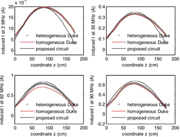
For the four frequencies represented in Fig. 6 (2 MHz, 30 MHz, 62 MHz and 90 MHz), the distribution of induced current along the body is sinusoidal for heterogeneous Duke as well as for the equivalent circuit. The induced current
100 101 102 10-2 10-1 100 in du c e d I at m id -he ig h t ( A ) Frequency (MHz) heterogeneous Duke homogeneous Duke proposed circuit
Fig. 5. Mid-length induced current in the heterogeneous, homogeneous Duke and in the equivalent dipole from 1 to 100 MHz
0 50 100 150 200 0 5 10 15 20x 10 -3 induc ed I at 2 M H z ( A ) coordinate z (cm) heterogeneous Duke homogeneous Duke proposed circuit 0 50 100 150 200 0 0.1 0.2 0.3 0.4 in d u c ed I at 30 M H z (A ) coordinate z (cm) heterogeneous Duke homogeneous Duke proposed circuit 0 50 100 150 200 0 0.5 1 induc e d I at 6 2 M H z ( A ) coordinate z (cm) heterogeneous Duke homogeneous Duke proposed circuit 0 50 100 150 200 -0.2 0 0.2 0.4 0.6 induc e d I at 9 0 M H z ( A ) coordinate z (cm) heterogeneous Duke homogeneous Duke proposed circuit
Fig. 6. Distribution of computed (for heterogeneous and homogeneous Duke) and determined using equation (15) induced current along human body at 2 MHz, 30 MHz, 62 MHz and 90 MHz
calculated by (15) is in a good agreement with that computed in the heterogeneous phantom (maximum deviation is 1 dB). The induced currents values at the feet (z between 0 and 20 cm) from the equivalent circuit and (15) are slightly lower than those of Duke (maximum deviation is 1.5 dB). For the head (z between 160 and 180 cm), the difference is higher (up to 8 dB at 2 MHz), but the limits on induced current given by ICNIRP [1] and IEEE [2] concern feet, so we consider our model still acceptable.
These results suggest that Thevenin equivalent circuit is an appropriate model for determining the induced current along the body for a plane wave exposure in 1 - 90 MHz range, particularly from feet to torso. From the Thevenin equivalent circuit (via Vth), we can describe induced current along the
body as a function of the external electric field. In the next section, the equivalent circuit and equation (15) are used to propose new limits on induced current more consistent with external electric field limits reported in [2].
IV. LIMITS ON INDUCED CURRENT DEPENDING ON EXISTING EXTERNAL ELECTRIC FIELD LIMITS
The limits on induced currents are defined for currents induced trough foot, so we consider that the induced current in foot can be measured at the ankle (z = 10 cm). For a controlled environment the standard limit through a foot is Ilimit = 100 mA
[2].
Using (15) and the proposed models, Fig. 7 demonstrates that to respect the actual limit on external electric field at 10 MHz (i.e.184 V/m), the induced current has to be lower than 80 mA. Between 30 and 90 MHz, the limit on external electric field is 61 V/m thus to respect those limits, the induced current in ankle has to be lower than 95 mA at 30 MHz and lower than 180 mA at 50 MHz, 70 MHz and 90 MHz.
Therefore the actual limits on induced currents are more restrictive than external electric field for frequencies above 40 MHz. For frequencies below 40 MHz, the limits on external electric field are more restrictive. However we did not take into account the coupling with the magnetic field because the phantom is isolated thus only sensitive to electric field [15]. Therefore the same study with the magnetic field coupling could be done because for frequencies below 10 MHz, the ratio E/H from ICNIRP limits is low impedance (lower than 377 Ω) [1]. 0 50 100 150 200 0 0.2 0.4 0.6 0.8 Electric field E (V/m) in duc ed I i n a n k le ( A ) 10 MHz 30 MHz 50 MHz 70 MHz 90 MHz
Fig. 7. Induced current in ankle as a fonction of external electric field at 10 MHz, 30 MHz, 50 MHz, 70 MHz and 90 MHz
CONCLUSION
An equivalent Thevenin circuit has been proposed to evaluate human body impedance and voltage at mid-height for a vertically polarized plane wave exposure in 1 - 90 MHz range. This circuit allows evaluating induced current along the human body depending on the external electric field for plane wave exposure. It provides an accurate estimate of the induced current compared to numerical results for a realistic human body model, particularly from feet to torso.
Finally, based on the proposed circuit and current distribution along the body, updated limits on induced current have been proposed depending on actual external electric field IEEE limits. This allows harmonizing induced current and external electric field limits, because currently induced currents limits are more restrictive than those of external electric field at frequencies above 40 MHz.
ACKNOWLEDGMENT
This work was supported by Thales Communications & Security, French National Association of Research and Technology (ANRT) and French National Center for Scientific Research (CNRS).
REFERENCES
[1] ICNIRP, “Guidelines for limiting exposure to time-varying electric, magnetic and electromagnetic fields (up to 300 GHz)”, Health Phys., vol. 74, pp. 494-522, 1998
[2] IEEE, “IEEE Standard for safety levels with respect to human exposure to radio frequency electromagnetic fields, 3 kHz to 300 GHz”, IEEE Std C95.1, 2005
[3] S. Tofani, G. d’Amore, G. Fiandino, A. Benedetto, O.P. Gandhi and J.Y. Chen, “Induced foot-currents in humans exposed to VHF radio-frequency EM fields”, IEEE Trans. on Electromagnetic Compatibility, vol. 37, pp. 96-99, 1995
[4] IEEE, “IEEE Standard for safety levels with respect to human exposure to radio frequency electromagnetic fields, 3 kHz to 300 GHz”, IEEE Std C95.1, 1991
[5] O.P. Gandhi, J.Y. Chen and A. Riazi, “Currents induced in a human being for plane-wave exposure conditions 0-50 MHz and for RF sealers”, IEEE Trans. on Biomedical Engineering, vol. 33, no. 18, pp. 757-767, 1986
[6] O.P. Gandhi and E.E. Aslan, “Human equivalent antenna for electromagnetic fields”, US Patent 5394164, Feb. 1995
[7] D. Poljak, C. Y. Tham, O.P. Gandhi and A. Sarolic, “Human equivalent antenna model for transient electromagnetic radiation exposure”, IEEE Trans. on Electromagnetic Compatibility, vol. 45, pp. 141-145, 2003 [8] B. Kibret, A.K. Teshome and D.T.H. Lai, “Characterizing the human
body as a monopole antenna”, IEEE Trans. on Antennas and Propagation, vol. 63, pp. 4384-4392, 2015
[9] A. Christ, W. Kainz, E. Hahn, K. Honegger, M. Zefferer, E. Neufeld, W. Rascher, R. Janka, W. Bautz, J.Chen, B.Kiefer, P. Schmitt, H. Hollenbach, J. Shen, M. Oberle, D. Szczerba, A. Kam, J. Guag and N. Kuster, “The Virtual Family – Development of surface-based anatomical models of two adults and two children for dosimetric simulations”, Phys. Med. Bio., vol. 55, pp. 23-38, 2010
[10] C. Gabriel, “Compilation of the dielectric properties of body tisses at RF and microwave frequencies”, Final Technical Report of Occupational and Environmental Health Directoral, 1996
[11] “The Visible Human Project”, available online at
http://www.nlm.nih.gov/research/visible
[12] S.A. Schelkunoff, “Theory of antennas of arbitrary size and shape”, Proceeding of the I.R.E., pp.493-521, 1941
[13] J.Y. Chen and O.P Gandhi, “RF Currents induced in an anatomically-based midel of a human for plane-wave exposures (20 – 100 MHz)”, Health Phys., vol. 57, pp. 89-98, 1989
[14] R. W. P. King, “Electric current and electric field induced in the human body when exposed to an incident electric field near the resonant frequency”, IEEE Trans. on Microwave Theory and Tech., vol. 48, pp. 1537-1543, 2000
[15] J. Frere, M. Zhadobov, R. Sauleau, C. Lemoine, A. Alcaras and G. Le Cadre, “Influence de l’impédance d’onde sur les valeurs de débit d’absorption spécifique pour un fantôme de l’humain en bande HF”, 18ème colloque international et exposition sur la compatibilité