This is an author-deposited version published in:
http://oatao.univ-toulouse.fr/
Eprints ID: 10604
To cite this version:
Dutilh, Vincent and Popa, Andreï and Dessein, Gilles and Alexis, Joël
and Perrin, Géraldine Impact of disturbed drilling conditions on the
surface integrity of a Nickel-base superalloy. (2010) In: CIRP ICME ’10 -
7th CIRP International Conference on INTELLIGENT COMPUTATION
IN MANUFACTURING ENGINEERING, 23 June 2010 - 25 June 2010
(Capri (Gulf of Naples), Italy).
O
pen
A
rchive
T
oulouse
A
rchive
O
uverte (
OATAO
)
OATAO is an open access repository that collects the work of Toulouse researchers and
makes it freely available over the web where possible.
Any correspondence concerning this service should be sent to the repository
administrator: [email protected]
Impact of disturbed drilling conditions on the surface integrity of a
Nickel-base superalloy
V.Dutilh
1-2, A.Popa
2, G.Dessein
2, J.Alexis
2, G.Perrin
1 1Turbomeca Tarnos, avenue du 1er mai, 40220 Tarnos, France
2
Université de Toulouse, INPT-ENIT, Laboratoire Génie de Production, 47 avenue d’Azereix BP1629 65016 Tarbes CEDEX, France
Abstract
Manufacturing critical parts for aerospace industry requires an important validation process to guarantee the quality of the produced components, and thus their fatigue life. Even with the best cutting conditions, disturbances can occur during the process and may have a direct impact on metallurgical quality. Through an experimental approach, this work presents the impact, during machining, of a lubricant interruption on the surface integrity and on the Process Monitoring signals. Finally a correlation between the thickness of the thermo-mechanically affected layer and the cutting power is made.
Keywords:
Process Monitoring, Surface Integrity, Micro-Hardness, Drilling, Udimet® 720
1. Introduction
The machining of nickel–base superalloy is complex and some small variations of the cutting context may generate Surface Integrity (SI) anomalies. If they occur in critical parts, these anomalies may have serious consequences. The validation processes, during which machining conditions are “frozen” after a metallurgical analysis, are today the only way to guarantee the “health” of the produced components. In this context, ACCENT project (Adaptive Control of Manufacturing Processes for a New Generation of Jet Engine Components) will allow the European Aero Engine manufacturers to develop Process Monitoring (PM) systems in order to control the machining and to reduce the validation costs of their critical components.
The aim of this paper is to establish links between Process Monitoring and surface integrity by testing different cutting conditions, either normal (with continuous lubrication) or disturbed (with lubricant interruption).
Firstly, a two dimensional domain of cutting conditions is defined according to the surface integrity criteria. Then, at the limits of this domain, the impact of the lubricant interruption shows that the disturbed conditions generate surface anomalies such as thermo-mechanically affected layers and that could be detected by an analysis of the Process Monitoring signals.
2. State of the art
Nickel base superalloys such as Udimet® 720 are frequently chosen for turbine disc applications. Generally, these alloys have good resistance against combinations of fatigue, creep, oxidation and corrosion damages. They are composed of an austenitic FCC (faced centered cubic) γ matrix strengthened mainly by coherent Nickel-rich Ni3(Al,Ti) γ’ precipitates, and some elements such as cobalt,
chrome, molybdenum and tungsten. Primary coarse precipitates γ’ are clearly visible at the grain boundaries and fine cuboidal γ’ are embedded coherently throughout the γ matrix [1].
Many studies on the difficulty in machining nickel-base superalloy have been performed but few on drilling and even fewer on drilling Udimet® 720. Furthermore, the majority of papers deal with tool wear and productivity in machining
Nickel-base superalloy. The influence of the lubrication compared to dry machining has been intensely studied, but few papers deal with the impact of lubricant interruption on surface integrity. In hole making, the tool life may be well controlled by measuring tool flank wear but this doesn’t guarantee the surface integrity [2]. The low thermal conductivity of this material leads to high cutting temperatures at the rake face which accelerates tool flank wear. The tendency of the γ matrix to work hardening and the rapid flank wear lead to a built-up edge formation. Built-up edge has consequences on surface roughness [4, 5]. In aero engine component manufacturing, a finishing operation like reaming or milling is necessary to eliminate residual stresses and work hardening generated by the roughing, and to improve the roughness specifications [2, 3, 4].
One of the most difficult steps, in aerospace industry machining, is the respect of the surface integrity and the understanding of the importance of each anomaly on the part fatigue life. An important study on this topic was the MANHIRP project [7] in which a reduction of 1E+01 to 1E+02 cycles on fatigue life was demonstrated for samples (Inconel 718 and TA6V) having the following anomalies: smearing, local microstructure deformation, adiabatic shear band or heavy distortion. Other studies have demonstrated the influence of white layer or residual stresses on fatigue life [2, 3, 6, 8]. Perrin [2] has defined four types of “anomaly holes” out of the domain defined by the COM methodology [9]. The four typical holes are described by the combination of the three following anomalies: isolated smearing, shear adiabatic band, and thermo-mechanical affected zone. Out of the four typical holes, the one with exclusively “non embedded isolated smearing” does not impact the part fatigue life. This underlines the difficulty of defining and detecting surface integrity anomalies.
Currently in aeronautical industry, an effort is conducted towards the Process Monitoring as a way to control machining. Many systems exist and are efficient to control the tool wear but are not designed to control the quality of the part produced. However, some experimentation gives interesting results in feed force, acoustic emissions or spindle power. For example, feed force in drilling can enhance a burr height change, the three phases of the drilling operation, the tool wear or the tool shipping [7]. The thickness of the thermo-mechanically affected layer could be
detected [10] or quantified by using the spindle power signal [2]. In the same way acoustic emissions may detect an abnormal drilling [7].
3. Experimental set up
The parts on which we carried out experiments were ∅80 mm forged bars, usually used for turbine discs manufacturing. These bars have the same heat treatments as the discs (solution and aged) in order to obtain the nearest characteristics to those of the discs (same microstructure, same grain size 8 ASTM, and same hardness 410 HV30). The only difference between the discs and the bars is the grain flow due to the last forging operation.
The tool is a ∅15.5 mm drill with an interchangeable TiAlN coated carbide head. This drill has the particularity of having a very short margin (4 mm), which avoids anomalies generated by frictions all along the hole [2].
All the tests were carried out on a 3-axis vertical milling center using a Siemens 840D numerical controller.
The machine-tool was instrumented by a 4 components Kistler dynamometer (Fx, Fy, Fz and Mz), and three accelerometers placed following the directions X, Y and Z. The spindle power, the position of Z axis, the intensity of the spindle and the motors intensity of the three axes are also recorded through the Siemens Profibus.
Finally, we designed an assembly to manage the drilling of 6 holes per bar and to make those holes systematically at the center of the dynamometer. In this type of dynamometer, the torque is measured by a sensor and not calculated as in a 3 components dynamometer (figure 1).
Figure 1. Experimental set up
4. Experimental plan
The objective of this work is to establish the relations through the cutting conditions between Process Monitoring signals and surface integrity anomalies.
The operation is a ∅15.5 mm drilling in a pre-hole ∅13 mm made by electrical discharge machining. The length of the hole is 37 mm. This operation is representative of the machining process of a critical part (disc) where the ∅13 mm pre-hole is a coring to make metallurgical analysis on the part material. We machined each hole with a new tool, to minimize the influence of the tool wear during the first millimetres and then to have a good reproducibility.
The first step of this work was to establish a two dimensional surface integrity domain according to the defined criteria (table 1) [10].The experimental procedure was based on the COM methodology so as to define the range of cutting conditions studied and to define a first SI window [10]. Then the upper limit of the first windows was
explored with a small discretization in order to better define the window established and to measure the reproducibility of trials.
The second step consisted in generating a 4 mm lubricant interruption (loose of pressure) during the drilling operation, located at 10 mm from the entrance of the hole. We chose to control the interruption in distance and not in time in order to always keep the same cut length during the lubricant interruption (even in different cutting conditions). Four cutting conditions were tested, one inside the Acceptable Surface Integrity Domain (ASID) and three outside. This disturbance, generates a sudden tool wear (according to the cutting conditions), which leads to a different type of signal and a different type of surface integrity from the ones at the beginning of the machining. This type of trials has two advantages; it expands the range of signals and the SI generated for a small number of trials and it creates two different situations on the same hole with the same tool. This step cannot be performed without previous normal tests which are necessary to understand what are the signals, the tool wear evolution and the surface integrity for “normal” tests are.
5. Results and discussion
5.1 Definition of Acceptable Surface Integrity Domain (ASID)
Metallographic examinations were carried out on all the experiments with an optical microscope (Olympus GX51), a scanning electron microscope (SEM-FEG JEOL 7000F) and a micro-hardness tester (SHIMADZU HMV).
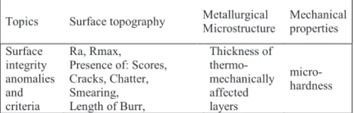
The surface integrity definition as shown in table 1 is a classification of anomalies in three main topics. Examples of anomalies and criteria to characterize anomalies are given.
Topics Surface topography Metallurgical Microstructure Mechanical properties Surface integrity anomalies and criteria Ra, Rmax, Presence of: Scores, Cracks, Chatter, Smearing, Length of Burr, Thickness of thermo-mechanically affected layers micro-hardness
Table 1. Surface Integrity anomalies classification.
In the holes which have been studied, the main anomalies observed are: chatters, smearing, burr, thermo-mechanically affected layers and material micro-hardness changes. The anomalies observed are taken into account separately but in reality they are always linked with one another.
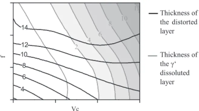
The accurate observation of the thermo-mechanically affected layer with the SEM shows that it corresponds to two layers. A layer characterized by a heavy distortion of grains and primary ‘ (black curves on figure 2) and a second layer characterized by a dissolution of the primary and secondary ‘ phases (grey curves on figure2). This dissolution indicates a local overheating and mechanical stresses. Figure 2 present the evolution of the thickness (µm) of the both layers compared to the cutting speeds. The thermo-mechanically affected layer is always associated with the work-hardening in sub surface, measured with the micro-hardness profile. Furthermore, the larger the thickness of the thermo-mechanically affected layer is, the deeper the influence of the work-hardening in sub-surface is. Further analysis with residual stress measurements will complete those observations. 4 Components Dynamometer Accelerometers Spindle axis Sample Z X Y
2 4 6 8 10 12 4 6 8 10 12 14 Vc f
Figure 2.Thickness (µm) evolution of the distorted and ‘ dissoluted layer vs. cutting speeds.
Observations carried out on each anomaly as made on figure 2, have permitted to establish a cutting domain without surface integrity damages (figure 3) with more precision than the previous one defined in paper [10].
On figure 3 the Acceptable Surface Integrity Domain (ASID) is also delimited for the low speeds but this range of speeds were not explored. The upper limit for the feed axis was mainly delimited by the roughness value and the distorted layer. The upper limit for the Vc axis was mainly delimited by the apparition of the ‘ dissoluted layer. In paper [10] the ASID was different but it was not the same machine and the rigidity of the first machine was lower.
The reproducibility of the trials is excellent under the upper cutting time limit when the tool wear becomes critical and ends up in the destruction of the cutting edge.
ASID Operating points f Vc C u tt in g t im e
Figure 3. Cutting conditions and Acceptable Surface Integrity Domain
During those trials some drillings show specific signals (a rapid increase in the cutting power recorded) which are easy to correlate with the thickness of thermo-mechanically affected layer and the micro-hardness sub surface profile all along the hole. This correlation was detailed in paper [10]. The lubricant interruption trials have also the particularity to reproduce this type of signals.
5.2 Results of the lubricant interruption on surface integrity and signals
Figure 4 presents the Intensity of the spindle during the drilling for each cutting conditions tested. Spindle Intensity is used because the signal is already filtered and presents the same topography as the power. The X axis represents the distance (mm) from the entrance of the hole and the Y axis is the intensity (A) value of the spindle. The black curve represents a normal operation without lubricant interruption. The grey curves represent two different drillings (new tools for each one) with the same lubricant interruption. The
lubricant interruption can be identified with the two consecutive decrease and increase in intensity. This is a consequence of the Z axis feed stop during data processing the lubricant interruption by the numerical controller, but the tool never leaves the material.
0 10 20 30 40 0 5 10 15 0 10 20 30 40 0 5 10 15 0 10 20 30 40 0 5 10 15 0 10 20 30 40 0 5 10 15
Figure 4. Spindle Intensity (A) vs. distance (mm) for four cutting
speeds
On the figure 4, for the cutting conditions 2 and 4 (CC2 and CC4), we observe that the experiments with lubricant interruption show a rapid increase in intensity compared to the normal drilling. The cutting conditions 1 (optimal operating point) do not present any change between signals. The cutting conditions 3 do not present a significant change between the curves with the lubricant interruption compared to the normal drilling. But this particular cutting condition is at the limit of Acceptable SI Domain (ASID) and in the case of normal drilling has a very important dispersion due to hazardous tool wear. Nevertheless the trials with lubricant interruption have an excellent reproducibility whatever the cutting conditions tested for the same experimental campaign are. These trials show that the combination of the cutting conditions with the lubricant interruption leads to an increase in signals amplitude (for all the measurement systems) except in optimal cutting conditions. However, the same phenomena (increased power, etc) were observed for the CC1 during another experimental campaign.
The same analysis with the accelerometers signals could be made but the temporal correlation is not possible without taking into account the frequency analysis. In our case the frequency analysis is complicated by our experimental set up. In fact the contribution of the dynamometer is not negligible, because the part fixture with the dynamometer has a natural frequency close to the first and the second natural frequency of the tool. This is the frequency domain where some variations correlated with drilling operations are expected. This more complex analysis is not treated in this paper. A future work will be focused on the way to extract the frequency contribution of the dynamometer on the Accelerometer signal in order to exploit this type of signals on a machine without a dynamometer.
5.3 Surface Integrity examinations
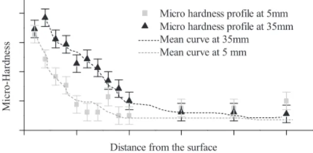
Surface Integrity examinations were carried out at 5 mm and at 35 mm from the entrance (dash lines on figure 4, CC2) on each hole which presented two different types and values of signals. Concerning micro-hardness measures, the load chosen is 0.1 kg which leads to have a print with 20 µm diagonal length. Figure 5 present two micro-hardness profiles (at 5 and 35 mm) for the CC4. This figure shows the influence in sub-surface of the drilling operation, and availability of the micro-hardness measurement as a criterion to define the surface integrity.
CC1 CC2 CC3 CC4 CC1 CC2 CC4 CC3 Thickness of the distorted layer Thickness of the ‘ dissoluted layer
Micro hardness profile at 5mm Micro hardness profile at 35mm Mean curve at 35mm Mean curve at 5 mm M ic ro -H a rd n e ss
Distance from the surface
Figure 5. Example of micro-hardness profiles at 5 and 35 mm from the
entrance of a hole with a lubricant interruption for CC4
5.4 Surface Integrity and Process Monitoring correlation
On each signal recorded, the mean, the standard deviation, the RMS, the skewness and the kurtosis value are extracted 1 mm around the SI analysis location. As detailed at the end of paragraph 5.1 the same correlation can be made between the evolution of the cutting power and the evolution of the thermo-mechanically affected layer thickness. This correlation is also available for the Power and the intensity of the spindle, the Mz value and the RMS value of the accelerometer.
Figure 6 presents the delta between the entrance and the exit of the hole of the thermo-mechanically affected layer thickness (sum of the distorted layer and the ‘ dissolution layer) compared to the delta of the corresponding cutting power. Paper [2] presents this type of analysis for normal drilling. Concerning this correlation, the power criterion is the most reliable because it takes into account the torque Mz and the axial force Fz of the drilling. Both SI criteria were added in order to be easier to measure but maybe they should be considered separately. In fact when the layer with the ‘ dissolution appears, the thickness of the distorted layer seems lower than just before. Although the influence of ‘ dissoluted layer on fatigue life is proved, that of the distorted layer on fatigue life is not confirmed. Furthermore, some papers deal with the benefits of work-hardening on the fatigue life. 0 10 20 30 0 50 100 150 200 D e lt a o f th e th ic k n es s o f th e la y er ( µ m )
Delta of cutting Power (W)
Figure 6. Delta of the thickness of the thermo-mechanically affected
layer vs delta of the cutting power (between measures performed at 5 and at 35 mm from the entrance of the hole)
This type of correlation is a first step in order to establish a model able to estimate in real time the thickness affected by the drilling operation.
This type of correlation is one of the Accent project objectives and it has to be completed by the same analysis extended to all SI anomalies and PM signals.
6. Summary
In this article, we have presented the results on the surface integrity through an experimental approach to generate disturbed cutting conditions (lubricant interruption). The trials were monitored with a four components dynamometer, a Siemens signals recorder and three accelerometers. Metallurgical analyses were performed on the holes produced, in order to identify and quantify surface integrity anomalies.
These have also permitted to establish correlations between the surface integrity anomalies observed on the holes produced and the Process Monitoring signals recorded during the experiments. The microstructure metallurgical changes were correlated to the cutting power signals.
In aeronautic critical parts manufacturing, the research or the optimization of cutting conditions are always subjected to metallurgical analyses. In this respect the Process Monitoring may be a solution to control the surface integrity and thus, simplify the validation process as well as guarantee the absence of any other manufacturing disturbances. This particular point represents the future development of our research.
Acknowledgments
The research leading to these results has received funding from the European Community's Seventh Framework Programme (FP7/2007-2011) under grant agreement number 213855.
References
[1] Pang H.T., Reed P.A.S., 2006, Microstructure effects on high temperature fatigue crack initiation and short crack growth in turbine disc nickel-base superalloy Udimet 720Li. Journal of Materials Science and Engineering, A 448, 67–79.
[2] Perrin G., 2007, Metallurgical, mechanical and thermal investigations on surface integrity for hole-making process in IN718. Detection and quantification of drilling anomalies by process monitoring. Phd thesis, Mines ParisTech graduate school.
[3] Sharman A., Amarasinghe A., and Ridgway K., 2008, Tool life and surface integrity aspects when drilling and hole making in Inconel 718. Journal of Materials Processing Technology , 200, 424-432.
[4] Kwong J., Axinte D., and Withers P., 2008, The sensitivity of Ni-based superalloy to hole making operations: Influence of process parameters on subsurface damage and residual stress. Journal of Materials Processing Technology, In Press, Corrected Proof. [5] Ezugwu E.O., 2005, Key improvements in the machining of
difficult-to-cut aerospace superalloys. International Journal of Tools & Manufacture 45, 1353-1367.
[6] Sharman A., Hughes J., and Ridgway K.,2006, An analysis of the residual stresses generated in Inconel 718(TM) when turning. Journal of Materials Processing Technology , 173, 359-367 (2006).
[7] MANHIRP Project, 2005, Integrating Process Controls with Manufacturing to Produce High Integrity Rotating Parts for Modern Gas Turbines. Final Report.
[8] Novovic D., Dewes R.C., Aspinwall D.K., Voice W., and Bowen P.,2004, The effect of machined topography and integrity on fatigue life. International Journal of Machine Tools and Manufacture, 44, 125-134.
[9] AFNOR Norm NF E66-520, 2000, Working zones of cutting tools - Couple tool-material.
[10] Dutilh V., Dessein G., Alexis J., Perrin G., 2009, Links between machining parameters and surface integrity in drilling Ni-superalloy, Int. Conf. on Structural Analysis of Advanced Materials-ICSAAM 09, Tarbes, September 7-10.