O
pen
A
rchive
T
oulouse
A
rchive
O
uverte (
OATAO
)
OATAO is an open access repository that collects the work of Toulouse researchers and makes it freely available over the web where possible.
This is an author -deposited version published in: http://oatao.univ-toulouse.fr/ Eprints ID: 4339
To link to this article: DOI: 10.1007/s10443-010-9128-0 URL:http://dx.doi.org/10.1007/s10443-010-9128-0
To cite this version: TRABELSI Walid, MICHEL Laurent, OTHOMENE Renaud. Effects of stitching on delamination of satin weave carbon-epoxy laminates under mode I, mode II and mixed-mode I/II loadings. Applied Composite Materials, 2010, vol. 17, n° 6, pp. 575-595.
ISSN 0929-189X
Any correspondence concerning this service should be sent to the repository administrator:
Effects of stitching on delamination of satin
weave carbon-epoxy laminates under mode I,
mode II and mixed-mode I/II loadings
WALID TRABELSI
Université de Toulouse ; INSA, UPS, Mines Albi, ISAE ICA (Institut Clément Ader), DMSM
ISAE, 10 avenue Edouard-Belin, BP 54032 ; 31055 TOULOUSE CEDEX 4
LAURENT MICHEL*
Université de Toulouse ; INSA, UPS, Mines Albi, ISAE ICA (Institut Clément Ader), DMSM
ISAE, 10 avenue Edouard-Belin, BP 54032 ; 31055 TOULOUSE CEDEX 4
* Author to whom correspondence should be addressed
RENAUD OTHOMENE
Composite Stress Engineering Department, Latécoère 135 rue de Périole, BP 5211, 31079 Toulouse Cedex 5
Abstract The objective of the present study is to characterize the effect of modified chain stitching on the delamination growth under mixed-mode I/II loading
conditions.
Delamination toughness under mode I is experimentally determined, for unstitched and stitched laminates, by using untabbed and tabbed double cantilever beam (TDCB) tests. The effect of the reinforcing tabs on mode I toughness is investigated. Stitching improves the energy release rate (ERR) up to 4 times in mode I. Mode II delamination toughness is evaluated in end-notched flexure (ENF) tests. Different geometries of stitched specimens are tested. Crack propagation occurs without any failure of stitching yarns. The final crack length attains the mid-span or it stops before and the specimen breaks in bending. The ERR is initially low and gradually increases with crack length to very high values.
The mixed-mode delamination behaviour is investigated using a mixed-mode bending (MMB) test. For unstitched specimens, a simple mixed-mode criterion is identified. For stitched specimens, stitching yarns do not break during 25% of mode I ratio tests and the ERR increase is relatively small compared to unstitched values. For 70% and 50% of mode I ratios, failures of yarns are observed during crack propagation and tests are able to capture correctly the effect of the
stitching: it clearly improves the ERR for these two mixed modes, as much as threefold.
Key Words Delamination. Polymer matrix composites. Stitching. mixed-mode fracture. Woven fabrics.
1.
Nomenclature
DCB: Double Cantilever Beam
TDCB: Tabbed Double Cantilever Beam ENF: End Notched Flexure
MMB: Mixed-Mode Bending
G: Total strain-energy release rate in mixed mode GI: Strain-energy release rate in mode I
GII: Strain-energy release rate in mode II
GIC: Interlaminar fracture toughness in mode I
GIIC: Interlaminar fracture toughness in mode II
C: Compliance P: Applied load
δ : Load point displacement b: Specimen width
a0: Initial crack length
a: Crack length
h: Thickness of specimen arm L: Specimen mid-span length
∆: Effective delamination extension to correct for rotation of DCB arms at delamination front
EI: Flexure stiffness
G12: Transverse shear modulus
G12c: Transverse shear modulus of composite laminates
Ga: Transverse shear modulus of the aluminium tab
χ: Correction factor for TDCB specimens
m: Slope of the plot compliance (C=δ/P) versus a3 c: Lever arm length in mixed-mode test
Y: Mixed-mode partition (GI/GII)
α, β : Material parameters used in power-law criterion
2.
Introduction
Laminated composites based on carbon fibres in a polymeric matrix are very attractive for applications in structures where high stiffness-to-weight and
strength-to-weight ratios are important. However, a limitation of many composite systems is their poor resistance to impact. This is a major deficiency for laminated composites.
Various techniques have therefore been developed to enhance damage tolerance by increasing the resistance to delamination growth. These techniques involve either material improvement or fibre reinforcement. Material improvement normally requires increasing the fracture toughness of the matrix resin, as delamination initiation and propagation occur mainly in the matrix material. However, with increasing demand for large allowable design strains and
reliability of aerospace structural components, material improvement alone is not sufficient.
Use of through-the-thickness reinforcement can lead to significant improvements in interlaminar strengths and delamination resistance. This can be achieved by transverse stitching [1] and z-pinning [2, 3] of laminated preforms or by using textile process technologies like weaving, knitting and braiding [4].
Stitching is well adapted to thin composite laminates while z-pinning is more efficient for thicker laminates. Even if the stitching yarn makes up only a few percent of the total fibre content of the composite, this technique greatly improves the interlaminar fracture toughness in mode I [6, 7, 8, 10, 11, 12] and mode II [13, 14, 6], as well as impact damage tolerance [5, 6]. The improvement in the
delamination toughness in mode I and mode II was found to depend upon the thread type, stitch type and density, stitching distribution and density. Wood et al. [12] reported that stitch distribution plays an important role in determining the steady-state strain-energy release rate. Experimental results show that, for similar stitch densities, stitches improve the critical strain-energy release rate in mode I,
GIC. Jain et al. [7] have found an up to 10-time increase in mode I fracture resistance of composite specimens made using a dry carbon fabric and resin transfer moulding (RTM) technique.
Regarding mode II fracture toughness, the authors [13] reported that stitches improve the toughness up to 4 times. Sharma and Sankar [6, 14] reported that the use of Kevlar-2790 as the stitching yarn improved the fracture toughness by about 15 times, Glass-1250 improved it by about 30 times, and Glass-750 by about 21 times.
For the development of an entirely composite aerospace structural component, a modified chain stitching technique has been chosen to reinforce some structural details such as the skin-stiffener cap joints. The general idea is to avoid any problems with delamination in these very critical areas. Therefore, the
improvement in interlaminar toughness due to this specific reinforcement has to be measured. This has to be done not only in pure modes I and II but also in mixed mode I/II. To our knowledge, the stitching effect has not yet been addressed in the literature for mixed-mode conditions.
Double cantilever beam (DCB) testing is an effective way to ascertain the mode I energy release rate (ERR) for unstitched laminated composites. It also can be used to evaluate the improved delamination toughness of stitched laminates. However, experimental studies observed that the stitched specimens fail in bending (high compressive bending stresses) using DCB testing [7, 8]. Therefore, a new DCB specimen configuration based on the design developed by Guenon et al. [9] was used by Jain et al. [10] and Wood et al. [11, 12]. To prevent premature failure of the cantilever substrate beams, specimens were bonded with a pair of aluminium tabs to either side along with loading blocks in order to apply a higher bending load in DCB testing. These studies show that tabbed double cantilever beam
(TDCB) specimens can effectively determine interlaminar toughness of stitched laminates.
Several test configurations have been proposed for mode II delamination toughness of carbon-epoxy composite laminates. The most commonly used of these is the end-notched flexure (ENF) configuration. General observations show that with unstitched specimens the cracking is unstable and instantaneously goes to the central loading pin, whereas the crack propagation in stitched beams is steady [13, 14]. The crack traction forces provided by stitches are sufficient to induce stable propagation and improve the toughness.
Different tests have been proposed for mixed mode [15, 16, 17], but some of them have limitations and do not permit testing of material for a broad range of mixed-mode ratios. The Standard ASTM Mixed-Mode Bending (MMB) test established for unidirectional carbon fibre tape laminates appears to be the best choice. The main advantage of this test method is the ability to obtain different mixed-mode ratios, ranging from pure mode I to pure mode II [18, 19]. This method can be used effectively to characterize mixed-mode interlaminar fracture of woven laminate specimens.
Consequently, the purpose of this study is, first, to examine the effect of stitching on mode I toughness. Unstitched carbon-epoxy laminate samples were tested under mode I using DCB and TDCB specimens to evaluate effects of the
reinforcing tabs on the determination of mode I toughness. Then the interlaminar fracture toughness is investigated and evaluated for TDCB stitched specimens. Second, the mode II fracture toughness is measured by subjecting unstitched and stitched specimens to end-notched flexure (ENF) tests. Third, the mixed-mode delamination behaviour of through-thickness reinforcement laminates is investigated using a mixed-mode bending (MMB) specimen. The fracture
mechanism is analyzed and the energy required for the initiation and growth of an artificial crack is calculated.
To complement visual observations, acoustic emission is used here to monitor damage accumulation before and during crack propagation and helps to define crack initiation. As reported by Sharma and Sankar [14], the crack surfaces do not open during the ENF test, and it is difficult to control the crack length during the experiment. X-ray imaging is used to estimate crack length after tests.
Experimental results are then gathered for unstitched and stitched specimens. An empirical criterion is identified for the unstitched composite fracture behaviour. Effects of stitching on these laminates are obtained and limits of this experimental study are given.
3.
Materials and experiments
3.1. Material systems
In this study, the composite specimens were manufactured by Latécoère from carbon woven-fabric 5H satin (Hexforce® G0926) and epoxy resin (Hexflow® RTM 6) using a resin transfer moulding (RTM) technique. A 13-µm high-performance release Teflon film was inserted at the mid-plane of the dry fabric laminates to simulate the crack defect. Two different kinds of quasi-isotropic laminates were manufactured: one 3 mm thick (8 plies) and the other 6 mm thick (16 plies).
The dry 2D laminates were stitched, before moulding, with Kevlar® stitching yarns. The type of stitch chosen for this study is the modified chain stitch® (Figure 1). This process is easy to implement requiring only one side access to achieve stitching (one-side stitching). The stitching density chosen for this study is 2.5 st/cm².
After consolidation, the plates were subjected to an ultrasonic C-scan to check quality and location of Teflon inserts. Following this process, the specimens were further cut and measured to the necessary dimensions for each type of test.
3.2. Specimens and testing procedures
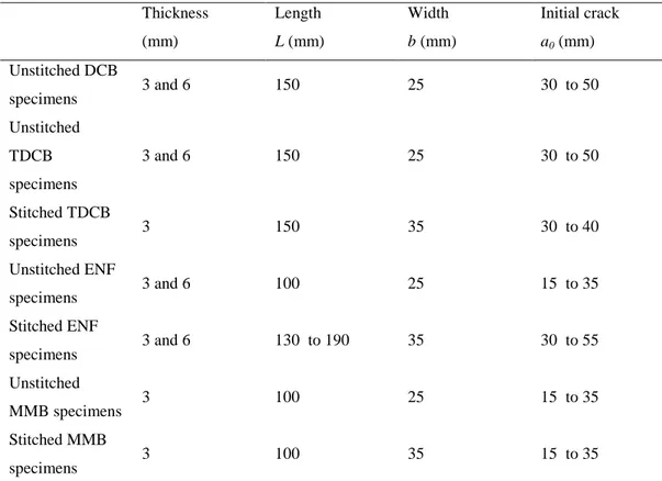
Table I summarizes dimensions and specific features of all specimens tested in the study. For stitched specimens, the width was increased (from 25 mm to 35 mm) in order to get a line of 4 stitch points across the width and thus obtain the stitching density required for this study.
Table I. Test specimens. Thickness (mm) Length L (mm) Width b (mm) Initial crack a0 (mm) Unstitched DCB specimens 3 and 6 150 25 30 to 50 Unstitched TDCB specimens 3 and 6 150 25 30 to 50 Stitched TDCB specimens 3 150 35 30 to 40 Unstitched ENF specimens 3 and 6 100 25 15 to 35 Stitched ENF specimens 3 and 6 130 to 190 35 30 to 55 Unstitched MMB specimens 3 100 25 15 to 35 Stitched MMB specimens 3 100 35 15 to 35
The thickness values in this table define specimens 3 mm thick (8 plies) and 6 mm thick (16 plies).
3.2.1. Mode I delamination
ASTM D5528 [20] describes the experimental determination of the opening mode I interlaminar fracture toughness, GIC. This method is used to ascertain the
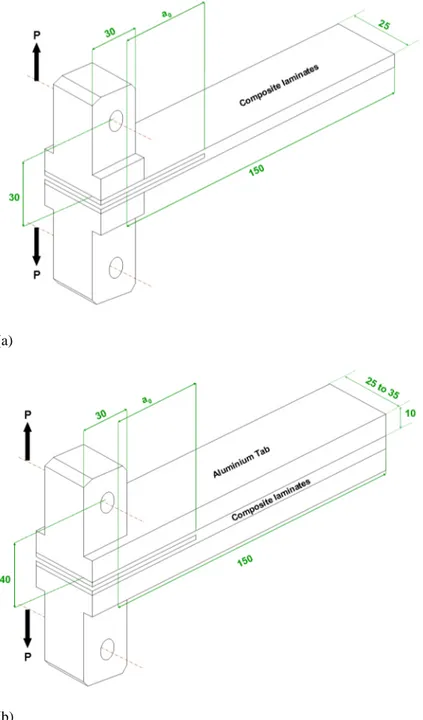
interlaminar fracture toughness of unstitched carbon-epoxy laminates. The crack length (a0) is determined from the loading point to the crack tip (Figure 2). On this side, loading blocks are bonded to either face of the specimen.
For the TDCB tests, aluminium tabs, 10 mm thick, are bonded to either side of both stitched and unstitched specimens using adhesive film (Figure 2). Loading blocks are directly machined on the tabs.
(a)
(b)
Figure 2. Schematic representation of (a) DCB specimen and (b) TDCB specimen for mode I tests.
3.2.1. Mode II delamination
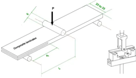
Mode II tests were performed using a three-point bending test. The main
advantage of the end-notched flexure (ENF) fixture is the ability to adjust the total span length (2L) of specimens (Figure 3).
The unstitched specimens were positioned in the fixture with a total span of 100 mm, and an initial crack length ranging from 15 mm to 35 mm.
For the stitched laminated composite specimens, the total span length varies between 130 mm and 190 mm for the two thicknesses (3 mm and 6 mm) studied here. The initial crack length depends on the span length and varies between 30 mm and 55 mm.
Figure 3. Schematic representation of ENF specimen for mode II test.
3.2.3. Mixed-mode delamination
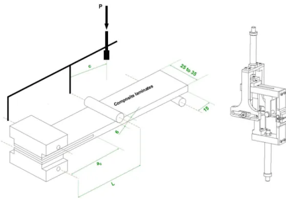
The mixed-mode bending (MMB) test method is adopted for this study. It is a simple combination of the DCB (mode I) and ENF (mode II) specimen (Figure 4). This standard ASTM test [21] is used to determine the strain-energy release rate (SERR) at various ratios of mode I and mode II loading. Three modal ratios were chosen (GI/G=25%, GI/G=50% and GI/G=70%). The initial crack length (a0) ranged from 15 mm to 35 mm.
Figure 4. Schematic representation of MMB specimen for mixed-mode test.
3.3. Test conditions
All tests were performed in a testing machine equipped with two load cells (1 kN for DCB and MMB tests and 25 kN for TDCB and ENF tests). The specimen is pin-loaded at constant displacement rates of 2 mm/min and then 0.5 mm/min to ensure slow propagation. The load and displacement are measured by reading signals from a load cell and a linear variable displacement transformer (LVDT) into a digital data logger used to record acoustic emission data during the test. Crack propagation is observed with the aid of an Olympus DP20 digital camera. The system includes an Olympus SZX10 stereo microscope (×1 to ×5
magnification) able to capture a high-digital-resolution image in real time during the test.
During these tests, the crack length is measured by visual observation with the aid of white marks along the specimen edge for unstitched and stitched laminates. Failure of stitch yarns is easily observed during mode I tests. In contrast, for mode II and mixed mode it is very difficult to conclude from visual observations. So, post-test X-ray imaging was used to determine stitch failures. Indeed, failed yarns absorb X-ray contrast agent and clearly appear on X-ray images (see Figure 16).
3.4. Analysis methods
The DCB test is used to determine the interlaminar fracture energy toughness,
GIC, for unstitched laminates. A load P is applied to each arm of a specimen with a delamination length a. The deflection of the specimen is measured by the displacement of the crosshead,
δ
. The energy rate for mode I, GI, is calculated using the Modified Beam Theory (Eq. 1).(
+ ∆)
= a b P I G 2 3δ
Eq. 1where b is the specimen width and
∆
is the effective delamination extension to correct for rotation of DCB arms at the delamination front. It is determined experimentally by generating a least-squares plot of the cube root of compliance,C1/3, as a function of delamination length (Figure 5). The compliance, C, is the ratio of the load point displacement to the applied load,
δ
/P.Figure 5. Correction factor for the modified beam theory (ASTM [20]).
For the TDCB specimens, the energy release rate is calculated using the Dransfield et al. formulation [10]. Assuming that each cracked substrate beam behaves as a cantilever of length a (the crack length), the deflection,
δ
(crack-opening displacement), may be estimated by summing a bending deflection term with a shear deflection term as follows:(
)
(
)
(
(
)
)
b
h
h
G
h
h
a
P
EI
h
h
a
P
a a a)
(
5
12
3
2
12 3+
+
+
+
+
+
=
χ
χ
δ
Eq. 2where ha is the thickness of the aluminium tab, EI is the flexure stiffness; G12 is the transverse shear modulus of the aluminium-composite beam and
χ
is a correction factor which takes into account the additional deflection due to the crack tip rotation of the beams. It can be determined from DCB and TDCB experimentally results of unstitched specimens.The energy rate for TDCB test, GI, is defined by Griffith’s energetic fracture criterion (Irwin-kies equation) [22], it is calculated as follows:
(
)
(
)
+ + + + = b h h G EI h h a b P G a a I ) ( 5 6 12 2 2χ
Eq. 3The expression for EI may be written as follows:
(
)
−
+
=
∑
∑
2 312
i i i i i cA
y
y
h
b
E
EI
Eq. 4 + + + = =∑
∑
a C a c a C a i i i i i i i h E E b bh h h E E h b h h b E A y E A y 2 2 Eq. 5Where y is the distance from the designated origin to the neutral axis (Eq. 5), y is the distance of the mid-point of each component from the same origin and A is the cross-sectional area of each component. Thus the expression for flexural rigidity may be simplified as :
−
+
+
+
−
+
=
2 3 2 32
12
2
12
h
y
h
h
E
E
b
h
E
E
b
h
y
h
b
bh
E
EI
a a C a a C a C Eq. 6 The interlaminar shear modulus of the system, G12, is given by the inverse rule of mixtures (Eq. 7).(
)
+
+
=
a a c aG
h
G
h
h
h
G
12 12 Eq. 7For unstitched and stitched ENF specimens, the beam theory formula is used to calculate the critical strain-energy release rate in mode II.
(
3 3)
2 23
2
2
9
a
L
b
a
CP
G
II+
=
Eq. 8For MMB specimens, the existing literature [18, 23] uses different methods to calculate the total mixed-mode strain-energy release rate, G. The MMB standard test method [23] describes the calculation of the GI and GII with the Modified Beam Theory method. However these methods are designed for unidirectional continuous fibre tape laminates and their application in our case posed some difficulties, particularly in identifying a consistent bending modulus.
Therefore, for our stitched and unstitched multidirectional fabric laminates, the experimental compliance method already used for fabric laminates [24] is chosen to compute the energy release rate, G. This method considers that the mode ratio is independent of the delamination length and the crack propagation is similar to mode II.
b
P
ma
G
2
3
2 2=
Eq. 9where m is the slope of the plot compliance (C=
δ
/P) versus a3. It depends on the mode ratio given by Eq 9.where c is the lever arm length. GI and GII can be calculated using the following expressions:
1
+
=
Υ
Υ
G
G
I Eq. 11Υ
+
=
1
G
G
II Eq. 12Υ
=
+
−
⋅
=
23
3
4
L
c
L
c
G
G
II I For 3c≥L Eq. 102.
Testing results and discussion
2.1. Unstitched and stitched mode I results
The results of DCB and TDCB test for unstitched specimens are shown in Figure 6. It depicts the load versus displacement for the two thicknesses (3 mm and 6 mm) studied here.
(a)
(b)
(d)
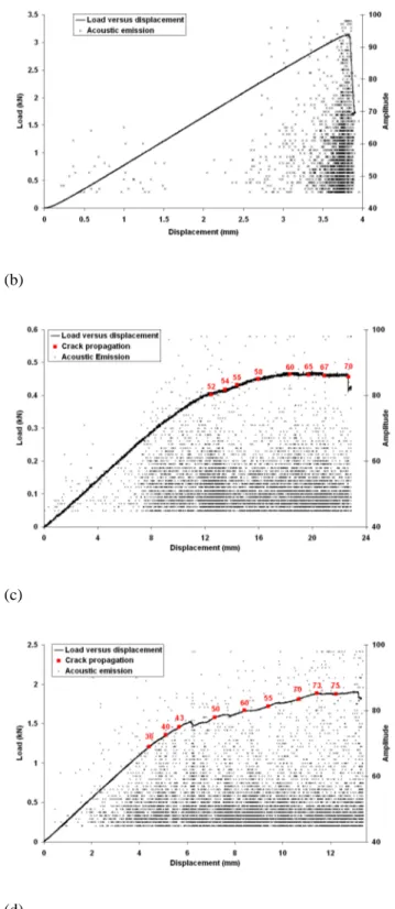
Figure 6. Load (P) and amplitude (acoustic emission) versus displacement (δ ) for unstitched specimens (a) 3-mm thick DCB (b) 3-mm thick TDCB (c) 6-mm thick DCB (d) 6-mm thick TDCB.
Acoustic emission monitoring reveals intense acoustic activity for all specimens before the load decrease, and starting from the point at which the
load-displacement curves become non-linear. The starting point of crack propagation is generally observed close to the top of (F/δ) curves. For DCB specimens, the load tends to decrease during crack extension but the propagation is unstable. Sudden load drops due to crack progress are observed and followed by slow recoveries of the load. It has been visually observed that such sudden crack progress is
associated with bridging effects due to the fabric pattern. For TDCB specimens, the aluminium tabs reduce the effects of the fibre bridging and the load decreases more steadily and slowly.
Concerning the thickness effect (from 3 mm to 6 mm), the peak load increases with the thickness of DCB unstitched specimens. The reason for this is the
increased stiffness, while for TDCB specimens increasing the composite thickness does not affect the load-displacement curve. The tabs increase the bending
stiffness of the specimen, thus hiding the stiffness increase due to a thicker laminate.
The curves of mode I delamination toughness (GI) versus crack length (a) for the unstitched specimens (3 mm and 6 mm thick) are shown in Figure 7.
(a)
(b)
(d)
Figure 7. GI versus crack length (a) for unstitched specimens (a) 3-mm thick DCB (b) 3-mm thick TDCB (c) 6-mm thick DCB (d) 6-mm thick TDCB.
The composite toughness curves reveal a linear increase in GI with the crack growth up to a point where the evolution flattens. A certain crack extension, called the process zone by Jain et al. [10], is needed to obtain stable propagation. The value of GI at the plateau is referred to as the critical propagation toughness,
GIC. The starting point of the plateau is shown by a vertical line (Figure 7). It can be clearly observed from the curves that the process zone of the unstitched 3-mm-thick specimens increased from 40 mm to 90 mm and from 60 mm to 70 mm for the 6-mm-thick laminates.
Experimental results for unstitched specimens, both tabbed and untabbed, exhibit a good agreement for the GI values. For 3-mm-thick DCB and TDCB specimens,
GIC is 803 and 853 J/m². The value at the plateau is 1017 J/m² (DCB) and 1024 J/m² (TDCB) for 6-mm-thick laminates.
These experimental data show that adding aluminium tabs causes an increase of the crack length needed to attain a steady-state behaviour and the critical
propagation toughness, GIC.
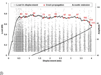
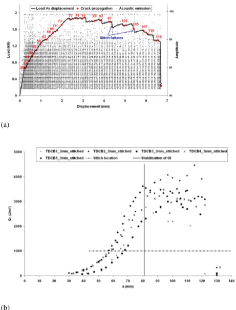
For the stitched specimens, there is an intense acoustic emission as soon as the load-displacement curve becomes non-linear (Figure 8). At this point the crack propagates quickly before reaching the first stitching yarns. Then its propagation slows down but goes on steadily. More stitching points become active in the crack wake until the first one fails at a local opening displacement of around 1.5 mm (Figure 9). This failure is accompanied by a substantial load drop (Figure 8).
(a)
(b)
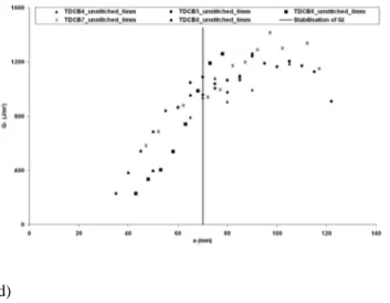
Figure 8. (a) Load (P) and amplitude (acoustic emission) versus displacement (δ ) for TDCB3_3-mm stitched specimen (b) GI versus crack length (a) for 3-mm-thick TDCB stitched specimens.
As the crack front reaches the first row of stitches, the R-curve slope rises rapidly with the increase of bridging entities and GI increases up to a critical value of length propagation. GIC is achieved after 81 mm of crack propagation with a value of 3500 J/m² (Figure 8). At this length of propagation, 8 rows of two stitches are active in the crack wake; this is confirmed by visual observations (Figure 9). The scatter of data points after this point can be attributed to the fracture behaviour of the stitch fibres. In comparison to unstitched specimens, it is immediately obvious that the addition of the through-the-thickness reinforcement by stitching improves the interlaminar toughness in mode I as much as fourfold, from 853 to 3500 J/m².
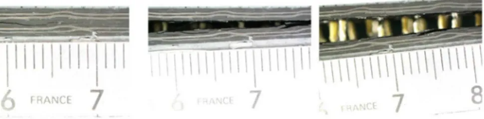
Figure 9. Photos displaying crack wake for 3-mm-thick stitched TDCB specimens.
2.2. Unstitched and stitched mode II results
For the unstitched specimens, as expected the crack propagation is unstable and leads to a sharp drop of the load. Close to this point, acoustic emission monitoring reveals intense activity (Figure 10).
For stitched specimens, depending upon the specimen geometry (L, h, a0), either the crack propagates up to the mid-span of the specimen (Figure 10: c-d) or it breaks in bending. For the first case, the load-displacement curves are initially linear. The observations show that crack starts to propagate on this part of the curve. Instead of a sharp load drop, a change of the P=f(δ) slope is observed with a steady crack propagation.
(b)
(c)
(d)
Figure 10. Load (P) and amplitude (acoustic emission) versus displacement (δ ) for ENF specimens (a) 3-mm-thick (a0=17, L=50, b=25) unstitched specimens (b) 6-mm-thick (a0=15, L=50, b=25) unstitched specimens (c) 3-mm-thick (ENF4_3mm a0=50, L=70, b=35) stitched specimens (d) 6-mm-thick (ENF2_6mm a0=35, L=75, b=35) stitched specimens.
Figure 11 shows the GII R-curves obtained for the unstitched specimens. As observed for mode I, GII increases slightly by increasing the thickness (from 3 mm
to 6 mm). The fracture-toughness energy seems to be stable for all the initial crack lengths. The average values of GIIC are 1605 and 2078 J/m² for unstitched 3-mm and 6-mm-thick specimens.
Figure 11. GII versus initial crack length (a0) for ENF unstitched specimens.
For stitched specimens, Figure 12 illustrates the evolution of GII as a function of crack length. The ERR is initially low and gradually increases with crack length. Further, for the two thicknesses (3 mm and 6 mm) the instantaneous toughness reaches very high values. GII increases as the crack propagates up to mid-span of the beam.
Figure 12. GII versus crack length (a) for ENF stitched specimens (3 mm and 6 mm thick).
The maximum values of ERR, determined when the crack reaches the mid-span length, are higher than experimental data obtained with unstitched specimens. Therefore, the stitches increase the ERR of woven laminates but much less than reported in the literature [13, 14], where the increase reached up to 15 times the fracture energy of unstitched specimens. It is important to note that there is no plateau in the GII R-curve where the GII is stable as is the case for mode I.
Even if the required energy for crack propagation is larger for stitched specimens, this additional energy is used to deform the stitches and is not high enough to break them. Indeed, X-ray images (Figure 13) obtained after test completion show that the stitches used in this study did not break. After testing, the cracked part of some specimens was cut. And it was impossible to separate by hand the two arms of these samples, showing that the stitching points remain safe. This also confirms visual observations made during the tests.
Figure 13. X-ray images and observations of ENF stitched specimens (a) 3 mm thick, (b) 6 mm thick.
To solve this problem and to obtain failure of stitches during experimental tests, changes were made in the geometry of specimens. The thickness (from 3 mm to 6 mm) and the mid-span length (up to L=95mm) were increased (see Figure 12, ENF3_6mm a0=45, L=95, b=35). However experimental tests showed that stitching yarns still did not break for this specimen. The maximum relative displacement of the two lips of the crack was of 1.05 mm (Figure 14) at the location of the first stitching row. That means this stitching is able to sustain a large extension before failure as it was observed for mode I.
Figure 14. Relative displacement of the two lips of the crack at the location of the first stitching row for 6-mm-thick stitched ENF specimens.
Wood et al. [25] recently presented a new version of the ENF test for the mode II delamination toughness testing of stitched woven laminates. They developed a tabbed version in order to avoid the premature failures in bending they observed for their materials. The authors reported that with this TENF version the stitches failed and the delamination front propagates up to the centre line of the loading point.
So a few more tests were performed with 3mm thick tabs bonded on each side of 3mm-thick specimen and here again crack propagations without any stitching failures were observed. This confirmed that under certain test configuration (i.e large span between supports) it is possible to obtain for the material under study steady crack propagation without any failure of stitching points.
Comparing to the standard results observed in the literature this behaviour has to be addressed. This might be due to a larger elongation capability of the stitching yarn or to the specific type of stitching: one side modified chain stitching or to a lack of tension of the yarn during the stitching process.
2.3. Unstitched and stitched mixed-mode I/II results
The load-versus-displacement curves for three MMB unstitched specimens are shown in Figure 15. The experiments presented in this figure correspond to the three modal ratios studied (GI/G=25%, GI/G=50% and GI/G=70%). For all the curves, the load increases in a single stage before progressively decreasing. Observations and X-ray images show that the crack reaches the mid-span of the beam for all the unstitched specimens tested.
At GI/G=70%, the slope of the decrease flattens. The propagation is unsteady as it was observed for the pure mode I (Figure 6). When increasing mode II ratio the load decrease becomes more and more pronounced after damage initiation and the crack propagation is more and more unsteady.
Observations and X-ray images show that the crack reaches the mid-span of the beam for all the unstitched specimens tested.
Figure 15. Load-versus-displacement curves for GI/G=70%, 50% and 25% (a0=25) for 3-mm-thick MMB unstitched specimens.
For stitched MMB specimens, the load-versus-displacement curves are shown in Figure 16 for the three modal ratios studied (25%, 50% and 70% of mode I). Figure 17 presents X-ray images and test observations of MMB stitched specimens.
Figure 16. Load-versus-displacement curves for GI/G=70%, 50% and 25% (a0=25) for 3-mm-thick MMB stitched specimens.
For GI/G=25% case, the load-displacement curve is almost linear. Then the load remains almost constant while the crack propagates quickly up to the mid-span of the beam. Observations and X-ray images show that stitching yarns did not break during this crack propagation.
In the case of the GI/G=50% MMB specimens test, the load-displacement curves show that the load decreases after damage initiation. At the end of the test, the average value of the crack length is 42 mm. The specimen fails in bending before
the crack reaches the mid-span length. X-ray images show eight failure points of the stitching yarn.
For the GI/G=70% case, the final crack length presents an average value of 33 mm and the specimen fails in bending. X-ray images show that six stitching yarns are broken.
Figure 17. X-ray images and observations of 3-mm-thick MMB stitched specimens (a) GI/G=70% (b) GI/G=50% (c) GI/G=25%.
Table II lists the experimental results for MMB stitched and unstitched specimens. For the cases of GI/G=70% and GI/G=50%, results show that the stitching
improves the fracture delamination toughness. The increase of Gis three times higher than with the unstitched specimens. For GI/G=25%, the value of G determined for stitched MMB specimen is only slightly higher than the fracture energy of unstitched specimens. The effect of stitching did not appear on
experimental values for this last modal ratio. The reason is that the stitching yarns did not break.
Table II. Total strain-energy release rate in mixed mode, G, for unstitched and stitched MMB specimens. Unstitched specimens GI/G (%) G (J/m²) GI/G (%) G (J/m²) GI/G (%) G (J/m²) 70% 1340 50% 1600 25% 1510 70% 1000 50% 1020 25% 1060 70% 880 50% 900 25% 1290 70% 1000 50% 810 25% 1230 70% 950 50% 1070 25% 1450 70% 780 50% 1230 25% 1890
Average 990±190 Average 1100±280 Average 1410±290 Stitched specimens GI/G (%) G (J/m²) GI/G (%) G (J/m²) GI/G (%) G (J/m²) 70% 4530 50% 3190 25% 2200 70% 3020 50% 3580 25% 1720 70% 4100 50% 4590 25% 1950 70% 1360 50% 4040 25% 1970 70% 3940 50% 4310 25% 3520 70% 2580 25% 1720
Average 3640±810 Average 4020±540 Average 2120±680
2.4. Mixed-mode delamination criteria
For unstitched and stitched composite laminates, it is interesting to know how the mode I energy contribution varies versus the mode II energy component. Many delamination fracture criteria were developed before obtaining consistent sets of mixed-mode experimental data. Early representations of the mixed-mode response were generally made by plotting GI and GII, data on a Cartesian coordinate system to define the fracture. The most widely used criterion to predict delamination propagation under mixed-mode loading, the power-law criterion, is established in terms of an interaction between the energy-release rates [26]. It contains the
The power-law criterion obtained with α=1 and
β
=1 was found suitable to predictfailure of composite laminates. This criterion simply normalizes each component of fracture toughness by its pure mode values [27].
The energy-release rate of 3-mm-thick unstitched specimens from experimental data is plotted on a GI-versus-GII chart as shown in Figure 17.
Figure 18. Mode I energy contribution, GI (Average values), versus mode I energy component GII (Average values), for 3-mm-thick unstitched and stitched specimens.
The correlation between values for unstitched laminates enables a linear criterion to be determined. The resulting curve on the mixed-mode fracture diagram is a line connecting the pure mode I and pure mode II fracture toughness as shown in Figure 18. It provides a good fit to the delamination toughness for the unstitched woven-fabric carbon/epoxy laminates.
For stitched specimens, experimental results determined on TDCB, ENF and MMB tests are plotted on the GI-versus-GII chart (Figure 18). For pure mode I,
GI/G=70% and GI/G=50% ratios, good values of fracture energy are found. Failures of yarns are observed during the propagation of the crack. Stitching clearly improves the fracture delamination toughness, as can be seen in Figure 18. On the other hand, for the stitched ENF and 25% MMB specimens, the
experimental results do not show any stitching yarn failures. As a consequence,
1 = + α β IIC II IC I G G G G Eq. 13 1 = + IIC II IC I G G G G Eq. 14
the effect of stitching remains limited and improvement of ERR is rather small compared to the other ratios. So, at this point of the study it is not possible to provide a consistent mixed-mode fracture criterion for these stitched laminates including the fully role of the 3D reinforcement.
However what must be highlighted is that for mode II dominated propagation there exist the possibility to get large crack propagation without any failure of the stitching. This might be a restraint to the application of this technique to
aeronautical structures where it is important to assess none propagation of the delamination at limit loads.
3.
Conclusions
For mode I, the experimental results for DCB and TDCB unstitched specimens are in a good agreement for the GIC values. Adding tabs increases the crack length needed to attain steady-state behaviour enabling measurement of the critical propagation toughness. For stitched specimens, the crack propagates quickly before reaching the first stitching yarns, and then after that point slowly and steadily. Yarn failure is associated with a substantial load drop on the load-versus-displacement curve. Experimental results in mode I show that stitching generates an up-to-fourfold improvement of the energy release rate, from 853 to 3500 J/m².
GIC is achieved after 81 mm of crack propagation. At this point, eight rows of two stitches are active in the process zone, with an opening relative displacement up to 1.5 mm.
As expected, the crack propagation of ENF unstitched specimens is unstable, i.e. associated with a sharp load drop. The ERR is stable in mode II. For stitched specimens, either the final crack length attains the mid-span or it stops before and the specimen breaks in bending. Observations and X-ray images show that the stitches do not break even if the crack propagates up to the mid-span length and the relative shear displacement of the 1st stitching row climbs up to 1mm. This specific behaviour may have several sources including type of yarn, of stitching point and even a problem of process and has to be addressed in the future. The ERR is initially low and gradually increases with crack length to very high values.
There are no plateaus in the GII R-curve and the maximum values are higher than experimental data obtained with unstitched specimens.
Concerning mixed-mode propagation of unstitched laminates a simple linear criterion has been identified. For stitched laminates, the first stage of the load-displacement curve of the GI/G=25% mode I ratio is almost linear. Then the load remains almost constant while the crack propagates quickly up to the mid-span of the beam without any failure of stitching yarns. The improvement in ERR is very slight compared to the values of unstitched specimens. For GI/G=70% and
GI/G=50% mode I ratios, the load-displacement curves show that the load decreases after damage initiation. Observations and X-ray images reveal that the crack propagates and the stitching yarns are broken before the specimen fails in bending. For these two mixed-mode ratios the stitching improves the ERR up to a factor of three.
25% MMB and ENF tests reveal no failure of stitches, which disables a fully-effect of stitching on ERR values to be obtained. This clearly reveals the fact that crack propagation is not stopped by stitching in mode II dominated delamination behaviour. On the contrary for TDCB, 70% and 50% MMB where the mode I ratio is higher crack propagation occurs with stitching failures. The reinforcement role of stitching is then fully achieved as measured by the large improvement of ERR values, up to threefold.
For aeronautical structures, this stitching will play the role it is expected to have when mode I is critical. When mode II becomes predominant, even if the stitching doesn’t improve largely the energy necessary to propagate the crack, it will likely lead to a stable propagation.
Acknowledgment
References
1. Mouritz, A.P., Leong, K.H., Herszberg I.: A review of the effects of stitching on the in-plane mechanical properties of fibre-reinforced polymer composites. Compos. Part A 28, 979–991 (1997).
2. Cartie, D.D.R., Partidge, I.K.: Delamination behaviour of z-pinned laminates. ICCM12 (1999).
3. Grassi, M., Zhang, X., Meo, M.: Prediction of stiffness and stresses in z-fibre reinforced composite laminates. Compos. Part A – Appl. Sci. Manuf. 33, 1653–1664 (2002).
4. Mouritz, A.P., Cox, B.N.: A mechanistic approach to the properties of stitched laminates. Compos. Part A 31, 1–27 (2000).
5. Liu, D.: Delamination resistance in stitched and unstitched composite plates subjected to impact loading. J. Reinforc. Plast. Compos. 9, 59–69 (1990).
6. Sharma, S.K., Sankar, B.V.: Effect of through-the-thickness stitching on impact and interlaminar fracture properties of textile graphite-epoxy laminates. NASA Langley Research Center, Hampton – Virginia (1995).
7. Jain, L.K., Mai, Y-W.: On the effect of stitching on mode I delamination toughness of laminated composites. Compos. Sci. Technol. 51, 331–345 (1994).
8. Chen, L.S., Sankar, B.V., Ifju, P.G.: A new mode I fracture test for composites with translaminar reinforcements. Compos. Sci. Technol. 62(10–11), 1407–14 (2002).
9. Guenon, V.A., Chou, T.W., Gillespie, J.W.: Toughness properties of a three-dimensional carbon-epoxy composite. J. Mater. Sci. 24, 4168-4175 (1989).
10. Jain, L.K., Dransfield, K.A., Mai, Y-W. : Effect of reinforcing tabs on the mode I delamination toughness of stitched CFRPs. J. Compos. Mater. 32, 2016–26 (1998).
11. Sun, X., Tong, L., Wood, M.D.K., Mai, Y-W.: Effect of stitch distribution on mode I delamination toughness of laminated DCB specimens. Compos. Sci. Technol. 64 (7–8), 967–981 (2004).
12. Wood, M.D.K., Sun, X., Tong, L., Katzos, A., Rispler, A.R.: The effect of stitch distribution on mode I delamination toughness of stitched laminated composites – Experimental results and FEA simulation. Compos. Sci. Technol. 67 (6), 1058-1072 (2007).
13. Jain, L.K., Dransfield, K.A., Mai, Y.W.: On the effects of stitching in CFRPs - II. mode II delamination toughness. Compos. Sci. Technol. 58(6), 829-837 (1998).
14. Sankar, B.V., Sharma, S.K.: Mode II delamination toughness of stitched graphite-epoxy textile composites. Compos. Sci. Technol. 57(7), 729-737 (1997).
15. Benzeggagh, M .L., Gong, X. J., Davies, P., Roedlandt, J. M., Mourin, Y., Prel, Y.: A mixed-mode specimen for interlaminar fracture testing. Compos. Sci. Technol. 34, 129-143 (1989).
16. Rugg, K.L., Cox, B.N., Massabo’, R.: Mixed-mode delamination of polymer composite laminates reinforced through the thickness by z-fibres. Compos. Part A 33, 177-190 (2002). 17. Davies, P., Blackman, B.R.K., Brunner, A.J.: Standard test methods for delamination resistance of composite materials: Current status. Appl. Compos. Mater. 5, 345 – 364 (1998).
18. Reeder, J. R., Crews, J. H.: Non-linear analysis and redesign of the mixed-mode bending delamination test. NASA TM 102777 (1991).
19. Reeder, J. R., Crews, J. H.: A mixed-mode bending apparatus for delamination testing. NASA TM 100662 Report (1988).
20. ASTM D5528-01. Standard Test Method for Mode I Interlaminar Fracture Toughness of Unidirectional Fiber-Reinforced Polymer Matrix Composites (2001).
21. ASTM D6671/D6671M-06. Standard Test Method for Mixed Mode I-Mode II
Interlaminar Fracture Toughness of Unidirectional Fiber Reinforced Polymer Matrix Composites (2003).
22. Irwin, G.R.: Analysis of stresses and strains near the end of crack traversing a plate, J. Appl. Mech. Transactions, 361-364 (1957).
23. Kinloch, A.J., Wang, Y., Williams, J.G., Yayla, P.: The mixed-mode delamination of fiber composite materials. Compos. Sci. Technol. 47(3), 225–37 (1993).
24. Benzeggagh, M.L., Kenane, M.: Measurement of Mixed-Mode Delamination Fracture Toughness of Unidirectional Glass/Epoxy Composites with Mixed-Mode Bending Apparatus. Compos. Sci. Technol. 56(4), 439-449 (1996).
25. Wood, M.D.K., Sun, X., Tong, L., Luo, Q., Katzos, A., Rispler, A.R.: A new ENF test specimen for the mode II delamination toughness testing of stitched woven CFRP laminates. J. Compos. Mat. 41 (14), 1743-1772 (2007).
26. Whitcomb, J.D.: Analysis of instability-related growth of a through-width delamination. NASA TM-86301 (1984).
27. Wu, E.M., Reuter, R.C.: Crack extension in fiberglass-reinforced plastics. TAM Report No. 275, University of Illinois, Urbana, Illinois (1965).
![Figure 5. Correction factor for the modified beam theory (ASTM [20]).](https://thumb-eu.123doks.com/thumbv2/123doknet/3694617.109702/12.892.212.378.616.795/figure-correction-factor-modified-beam-theory-astm.webp)