Science Arts & Métiers (SAM)
is an open access repository that collects the work of Arts et Métiers Institute of
Technology researchers and makes it freely available over the web where possible.
This is an author-deposited version published in:
https://sam.ensam.eu
Handle ID: .
http://hdl.handle.net/10985/11349
To cite this version :
Franca GIANNINI, Erika MONTANI, Marina MONTI, Jean-Philippe PERNOT - Semantic
Evaluation and Deformation of Curves Based on Aesthetic Criteria - Computer-Aided Design and
Applications - Vol. 8, n°3, p.449-464 - 2011
Any correspondence concerning this service should be sent to the repository
Administrator :
archiveouverte@ensam.eu
Semantic Evaluation and Deformation of Curves Based on Aesthetic
Criteria
Franca Giannini1, Erika Montani1, Marina Monti1 and Jean-Philippe Pernot2 1Istituto di Matematica Applicata e Tecnologie Informatiche – CNR, giannini@ge.imati.cnr.it, s2860716@studenti.unige.it, monti@ge.imati.cnr.it
2Arts et Métiers ParisTech, LSIS Laboratory, UMR CNRS 6168, jean-philippe.pernot@aix.ensam.fr
ABSTRACT
To better simulate the way designers work, specific tools are needed to handle directly specific shape features meaningful for the design intent, without focusing on the underlying mathematic representation. For this purpose it is fundamental to identify proper higher-level shape descriptors as well as the corresponding manipulation techniques. The paper presents the definition and implementation of semantic operators for curve deformation based on a shape characterization that is specific to the industrial design context. The work grounds on the innovative approach suggested by the FIORES-II project for the intent-driven modeling tools for direct shape modification and on the multi-layered architecture proposed by the Network of Excellence AIM@SHAPE for the definition of semantic-oriented 3D models. In particular the paper proposes the use of meaningful aesthetic features for the evaluation of planar curve signature and for their intent-driven direct modification. Keywords: geometric modeling, styling, aesthetic features, semantic-oriented 3D modeling.
DOI: 10.3722/cadaps.2011.xxx-yyy
1 INTRODUCTION
The definition of tools more suitable for the mentality of creative users is one of the still open critical issues in the computer-aided design of industrial products. Several results have been obtained in providing various curve and surface manipulation functionalities to obtain high quality curves and surfaces through the specification and control of the curvature [5][6]; however, as far as we know few results have been obtained in terms of intent-driven modification. In geometric modeling, the feature-based approach aims at facilitating the design activity while enabling shape-oriented manipulations directly linked to the semantics the user has in mind. A form feature is what makes different (functionally in the mechanical design, and aesthetically in the styling domain) two objects that were initially defined by the same overall geometry. While the features defined for mechanical CAD systems are mainly related to canonical geometric shapes, easy to classify and allowing a better association between shape and function, in the styling practice, being a creative process, the designer needs a
certain freedom of expression that would take into account personal tastes, visual impressions, fashions, etc.; consequently, features are intended as complex high level entities that allow a faster creation and modification of the geometric model. In literature, it is possible to find several studies focusing on the user interactions with shape product through free-form features [12]; there are various meaningful proposal for classification of free-form features [2][7] [16], and several interesting works [13][18] dealing with the shape modification by features but they are hardly taking into account aesthetic information; only few consider aspects, such as brand character or emotional feeling but are very peculiar to specific products and not generally applicable.
Defining a strict link between geometric characteristics and aesthetic features is not immediate due to the multitude of the possible shapes and to the fuzziness of the concept of aesthetics. In this context, we must understand which elements are meaningful both for the design and the style judgment: sometimes, derived features are more important for checking the aesthetic quality of the model than the constructive ones. Actually, stylists normally judge the aesthetic character of the product from the flow of certain lines that have no explicit representation in the product model, but can nevertheless be perceived, such as the lines originated by the reflection of the light on the object. Such lines are not belonging to the object model but are derived from it by calculations. Thus, they could be considered both as properties or as features of the model: on the one hand they reveal properties of the underlying surface (all surface points on the lines share the same geometric property, e.g. same angle between the normal to the surface and the light ray), on the other hand they are feature lines with their own set of properties. We regard as styling features both derived and constructive elements as long as they are connected with the aesthetic impression of the object (in contrast to engineering features, which modify the shape for functional or technical reasons). They also carry information about the technical quality (e.g. surface continuity) but mainly about the aesthetics and sometimes the emotional character of the product.
In [8] authors describe a tool developed in the course of the project FIORES-II [8], to allow designers both maintaining the aesthetic character during engineering optimizations and to facilitate the achievement of product shapes respecting a given image word. The association between shape and image terms relay on the concepts of styling features and aesthetic properties. These last correspond to the terms used by designers to indicate the wished shape changes (i.e., dynamic or accelerated curve), while styling features are the curves which are modified to drive the wished 3D shape changes and image words are those used by marketing people to describe the product aesthetic character. Some of the aesthetic property terms have been translated in modelling and measuring operators directly acting on the geometry to obtain the desired shape results.
The work presented in this paper is grounded on the results summarized in [8] and extends and integrates these results within the approach proposed by the AIM@SHAPE network of excellence [1] for the definition of multi-layered semantic oriented 3D models. The main objective is to define and implement semantic operators to deform curves, based on a shape characterization in terms of styling features: providing functionalities for the evaluation of aesthetic properties of styling features, a semantic-driven deformation directly acting on the styling features modifying their property values becomes possible. In particular, the paper focuses on the straightness aesthetic property implementation. It also illustrates the exploitation of this property for making more accurate the adopted qualitative curve description, indicated as curve signature, originally based on Leyton’s shape grammar [10]. Method for preserving the curve signature during curve modification is presented as well, aimed at guaranteeing shape tuning according to the wished property values. The paper is organized as follows: the first part of the paper describes the implementation of the toolbox for evaluating specific aesthetic properties and how the estimated measures may be used for assessing a curve signature meaningful for styling. The second part focuses on the deformation engine implemented on top of the shape characterization defined by the aesthetic properties.
2 A SEMANTIC MODELLING MULTI-LAYERED APPROACH FOR STYLING
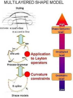
In the context of a semantic-based approach for curve modelling, the AIM@SHAPE [1] project proposed a conceptualization of a multi-layered architecture according to which shape models are organized at three different levels of increasing information abstraction: geometric, structural and semantic layer (see Fig. 1.)
The geometric level is the representation of the shape data, in which different types of geometric models can be used (e.g. NURBS, 3D mesh). At the structural level elements are grouped and associated to abstracting elements according to some shape or topological characteristic (e.g. curvature evolution, connected object components). At the semantic level the association between shape model parts and their associated semantics is made explicit, through annotation of shapes according to the specific application domain.
In product design, at the lower geometric layer, NURBS representation [14] enables direct manipulation of the shape, through the interaction with its control points or by imposing specific constraints on the geometric parameters defining the shape.
In the higher level it is possible to exploit all the available knowledge to create semantic-driven operators which act on the curves, strictly connected to the stylist's point of view, thus allowing a much more simple and natural mode of interaction. This level therefore permits to define and manipulate the model by the use of the free-form features, and to act on them by adjusting their aesthetic properties.
The aim of the structural layer is to fill the gap between the two other layers and to be the interface for sharing information and data with the other actors of the product design activity, allowing an independence from possible different geometric construction methods and representations. For this reason, this intermediate level should be easily and automatically obtainable regardless of how the object is represented and built. The structural level is seen as a neutral environment in which the curves are classified and treated through the intrinsic information related to the curvature; to this aim, here we started from the Leyton’s shape grammar [10] that provides a classification of the curves through a name or signature, that is a sequence containing information on curvature extremes and inflection points; this structural representation can take into account the possible evolutions of the shape providing a form of possible history inside a shape.
Nevertheless, the curve description based on the Leyton's grammar is not accurate enough to give a satisfactory curve classification; therefore, it is necessary to add further information for a more specific characterization of curves, like the characterization in terms of aesthetic properties, which we propose in the following.
2.1 The Leyton Grammar and Curve Signature
A shape grammar is a grammar where the symbols of the alphabet and the generated strings are interpreted and visualized as geometric entities. Grammar-based design systems have the potential both to automate the design process and allow greater exploration of design alternatives. We started from a curve description based on the extension of the shape grammar defined by Leyton [10], and the specification of a set of manipulation operators. Leyton proposed a shape process grammar based on the analysis of the curvature, aiming to characterize the shape and expressing any shape evolution in terms of six types of phase-transitions, by suggesting a rule system for deducing the past history that formed any shape. For example, the shape in Fig. 2(a). can be seen as the result of various processes inferred at a circle. The Process-Grammar relies on two structural factors in a shape: symmetry and curvature. The symmetry axis of a shape is the locus of points Oi, which are the midpoints of the arc AB of a circle moved along the shape and always tangent to the shape at these two points A and B (Fig. 2(c). ).
Symmetry axes are closely related to process-histories; actually, according to Leyton, they are the directions along which processes are hypothesized as most likely to have acted.
The Leyton's shape grammar is built considering only the intrinsic properties of the curvature evolution, which is independent from the geometric representation, but very important from the shape perception point of view; in particular curvature extremes and inflection points have been chosen as the basis for the symbolic curve description.
These specific points related to the curvature are referred as characteristic points and they are classified as in the following:
• M+ for a positive maximum, • m+ for a positive minimum, • M- for a negative maximum, • m- for a negative minimum, • 0 for an inflection point.
Fig. 2: Symbolic description of a C2 continuous curve: a) grammatical description of a smooth curve, b) curvature plot, c) definition of the symmetry axis.
Fig. 3: Two ellipses have the same name.
With this classification, the name of a curve is defined as the sequence of its characteristic points, reading the curve from the curvilinear abscissa 0 to the end of the curve; for example, the curve in Fig. 2(a). has name "M+ m+ M+ 0 m- M- m- 0 M+ m+".
Moreover, if two different curves have the same name, it is said that they belong to the same class; for example, since all the ellipses are described by the name "M+ m+ M+ m+", they are part of the same class, which also contains other types of curves. Nevertheless, the information contained in the name refers only to the curvature extrema and inflection points, and no others advices in between two characteristic points are given. Thus, two curves with the same name might appear very different from an aesthetic point of view: for example, let E1, E2 be two ellipses, having respectively major semi-axes
1
a
;b
1 and minor semi axesa
2;b
2, witha
1 >>b
1 anda
2»
b
2, as shown in Fig. 3; every ellipses presents the same name M+ m+ M+ m+, but the impression when looking at them may be very different. For this reason, it might be interesting to add further elements at the name in terms of properties that would allow obtaining a more refined classification meaningful for the styling point of view.2.2 Aesthetic Properties Evaluation
In the framework of the FIORES-II project, the characterization of shapes in terms of styling features and their property from an aesthetic and emotional point of view have been deeply analyzed. Among the various outcomes achieved, it emerged that different languages are adopted in different phases of the product design process (marketing, designers, Computer-Aided Styling). In particular, during the creation and modification of the product model, stylists express detailed directives when they work with surfacers at the definition of the 3D digital model using a limited number of terms strictly linked to shape properties: with these terms they provide instructions for the modification of the product shape (e.g. making a curve a bit more accelerated, or decreasing its tension). The terms mostly used in this phase by designers, namely the aesthetic properties, are :
• Softness/Sharpness • Hard/Crude • Lead in • Tension
• Acceleration • Convexity/concavity • S-Shaped • Hollowness
• Crown • Straightness/Flatness
Even if these terms cannot be considered as a complete lexicon for styling, nor do stylists use all this concepts, it has been proved that is extremely useful to exploit the knowledge that is implicitly inside these terms. Properties’ characterization and measures (or more generally shape descriptors) play a key role: they are useful tools to formally characterize the property of the shape which has to be modified focusing on the possibility of translating the concepts linked with the aesthetic properties in an environment able to treat the geometrical entities from a mathematical point of view. For this
reason, it is necessary to find meaningful measures for property evaluation allowing the control of the shape; actually, by monitoring these values and correspondingly acting on the associated geometric properties, it could be possible to obtain a required modification of the shape; in particular, what is interesting in the modification process is the capability of modifying the curves by increasing or decreasing these values.
In [15] and [8] authors illustrate the meanings and the measures of the above listed properties and the implementation of the corresponding modification operators. In this work we have modified and implemented the measures for some of the FIORES-II aesthetic properties, namely convexity,
acceleration, s-shaped and straightness, by using a quite standard library for mathematical
computation (i.e. MATLAB ©), in order to allow the complete independence from any commercial CAD system. In particular in this paper we focus on the straightness property, illustrating the proposed new measure and the implemented operator.
2.2.1 Straightness measure definition and implementation
In engineering straightness is referred to a straight line; in free-form modelling of styling objects true straight lines are rarely appearing, nevertheless the tendency to straight lines for surface sections and profiles is frequently looked for. Stylists define the straightness property as the capability of a curve to resemble a straight line. Therefore the straightness measure should give precise information on the deviation of the curve from the straight line. In this perspective, we find that the measure provided in the FIORES-II project is quite rough. For example it weakly considers the quantity of oscillations a curve may have, which actually can influence the perception of the curve. The emerged drawbacks suggested to refine such a measure, taking into account all those elements which seem to be meaningful to characterize the straightness of a curve. Then a new measure is proposed:
l
L
A
C
ss
straightne
non
_
=
×
2×
(2.1)where, C(u) = (x(u), y(u)) with
u
Î
[
0
,
1
]
is the curve in parametric form, k(u) is the curvature of C(u)du
u
k
C
=
ò
] 01 [)
(
is the integral of the absolute value of the curvature,=
ò
×
] 1 , 0 [)
(
)
(
)
(
u
x
u
d
u
y
A
!
is the valueof the area between the curve and the cord that joins the two extremes of the curve,
du
u
y
u
x
L
=
ò
+
] 1 , 0 [ 2 2(
)
)
(
!
!
is the length of the curve andl
is the length of the cord.The factor C gives information on how much the curve deviates, in terms of curvature, from the straight line, because it has curvature equal to zero; the factor A also evaluates the deviation from the straight line, but in terms of area of deviation; the factor
l
L
evaluates the presence of oscillations of the curve, indeed the more oscillations the curve has, the bigger is this value. The second factorl
at the denominator is necessary to enable this formula to be independent by the scale; actually, if the curve is scaled with a factor n, the values of the factors change according to Tab. 1.:scale 1 scale n
C C/n
A A• n2
L L• n
l L• n
Fig. 4: Some examples of straightness evaluation.
For the measures A, L and l, this relation is trivial because they are measures of area and length; for the measure C, it can be understood by considering the formula of the curvature k(u) of a B-spline curve (written in the parametric form C(u) = (x(u), y(u)) ):
2 3 2 2
(
)
)
)
(
(
)
(
)
(
)
(
)
(
)
(
u
y
u
x
u
x
u
y
u
y
u
x
u
k
!
!
!!
!
!!
!
+
-=
The first and the second derivatives are directly proportional respectively to n and n2, so C results inversely proportional dependent with the scale factor of the curve. The values of the non_straightness vary between 0 (corresponding to the straight line) to ∞ (there is not an upper limit for the deviation of a curve). In order to obtain an appropriate measure of the straightness, this formula is converted by applying the transformation:
Fig. 5: (a) Evaluation of the straightness of the curve segment between u=0.5 and u=0.7. (b) The evaluated curve segment in its local coordinate system.
ss
straightne
non
ss
straightne
_
1
1
+
=
With this transformation an evaluation of the straightness which takes values in the interval (0,1] is achieved: the only curve with straightness 1 is the straight line, and the more is the value near to zero, the more is the curve far from the straight line.
Once defined the measure, the function straightness for its evaluation can be implemented. In Fig. 4. some examples of evaluations of the straightness measure are presented.
Regardless of the length and the kind of the curve, the user might want to focus only on the evaluation/deformation of just a segment of the curve. Therefore it is necessary to define tools able to compute the straightness value of portions of the curve: this will lead us to better control the shape of the curve.
Let
P
1=
C
(
u
*1)
andP
2=
C
(
u
*2)
(u
*1,
u
*2Î
[
0
,
1
]
) the two extremes of the curve segment;the function straightness can be easily adapted at this case and the function straightness_segment has been created, just by considering the segment curve between
P
1 andP
2.In Fig. 5. an example of the application of the function straightness_segment. 2.3 Refining the Curve Signature
We can exploit the capability of evaluating the straightness property to add further elements at the curve name to obtain a more refined classification of the curves meaningful from the aesthetic point of view. We propose to establish a vocabulary according to which the curves are classified depending on their value of the straightness. After analyzing many examples, the vocabulary of the straightness which seemed more significant was defined as (Fig. 6.):
1 the straight line à SS [0.98,1) very straight à S [0.9, 0.98) fairly straight à s [0.7, 0.9) not straight à ns (0,0,7) very not straight à nS
Fig. 6: Examples of straightness measure of different curves.
The curve signature based on the Leyton Grammar has been extended and improved by means of the evaluation of the straightness for each segment, corresponding to the portion of the curve in between two characteristic points, and the information in terms of the vocabulary defined above is added at the original name. In this way, the signature for the two ellipses in Fig. 3. becomes: E1= M+S+m+SM+Sm+S and E2 = M+sm+sM+sm+s. Therefore, accordingly to the signature, the two ellipses can be distinguished within the same class.
3 THE DEFORMATION ENGINE
The ultimate objective of this work is to create operators acting on the aesthetic properties, according to the other possible imposed requirements and/or maintaining unchanged some shape properties. For example, in our grammar-based environment, in which every curve is classified according to the information contained in its name, being able to modify a curve while preserving its connotation, which means to apply a modification only inside a class, ensures that certain shape characteristics are maintained.
Moreover, to be able to act only on the aesthetic property of a specific portion of a curve, preserving G1 or G2 continuity conditions at the extremes could be very important in aesthetic design process. The mathematical definition of the straightness measure (Eqn. 2.1), as well as the other property measures, is the bridge linking the aesthetic intent of the stylist to act on specific aesthetics aspects, and the setting of appropriate tools able to modify the curve in response of the imposed requirements. This requires a geometric modelling tool able to act on the related underlying geometric characteristics, in other words, a deformation engine able to manipulate the curve under a set of local and global constraints.
Constraint-based deformation is a procedure widely used in current modern CAD systems. In [4] it is proposed a taxonomy of the constraints classically used for curve and surface modelling, and the various ways a user can express them; four semantic levels are defined according to the type of the constrained entity, which can be covered by two types of specifying constraints: strict and soft constraints.
Strict constraints have to be closely respected by the modeller during the shape creation and
manipulation processes; they are commonly named geometric constraints in the literature because directly related to geometric parameters. Here, two types of constraints can be taken into account:
• global constraints if they act on the entire entity. They refer to some integral properties of the curve/surface, as for example preserving the length or a prescribed area of the curve;
• local constraints, if they are applied only to an arbitrary subset of the entity. They are used to locally control a shape, for example through a set of point constraints like position constraints, tangent and normal constraints and curvature constraints.
Moreover strict constraints can be classified in direct (if the constraints are applied on a geometric entity) and indirect (if the constraints are defined without a geometric entity as reference).
Soft constraints can be of various types and sometimes it is difficult to express them in a
mathematical form. These constraints do not have to preserve a strict value during the deformation process, expressing the final aspect of a component shape or at least, the expectation to obtain a solution close to it; for example the constraint of requiring a rather smooth curve, or a sharper blending.
In our context, according to this taxonomy, the aesthetic property may be seen as soft constraints (i.e. requiring a curve a bit more straight). However, the mathematical formalization of the aesthetic measures allows such constraints to be also considered as an indirect strict constraint, either global or
local, depending if it is related to the whole curve or to a portion. In addition, also direct and indirect local strict constraint can be simultaneously applied to specific points of the curve (e.g. curvature
value, position and tangency constraints). The curve deformation is defined in such a way that the new elements defining the modified curve (the coordinates of the new control points) are found while the resulting curve satisfies the imposed constraints, expressed into a mathematical environment by systems of equalities or inequalities to be solved. Once the constraints are defined, one curve among all the possible ones which could satisfy the constraints has to be selected. For this reason it is necessary to add a further condition, the 'objective function' F to be minimized (generally called the minimization condition).
The straightness is a nonlinear constraint because of the nonlinearity of the straightness measure (Eqn. 2.1). In mathematics, nonlinear programming is the process of solving a system of equalities and inequalities (constraints), over a set of unknown real variables, along with an objective function to be maximized (or minimized), where some of the constraints or the objective function are nonlinear. In our context, the constrained optimization problem can be formalized as:
Beq
X
Aeq
×
=
(3.1)B
X
A
×
£
(3.2)0
)
(
X
=
Ceq
(3.3)0
)
(
X
£
C
(3.4)))
(
min(
F
X
(3.5) Where: ) 1 ( 2 +Î
R
nX
is the unknown of the problem, namely a vector containing the coordinates of the control points (n + 1 = number of the control points);B
Beq
A
Aeq
,
,
,
are respectively real matrix and vectors representing the linear equality and inequality constraints;Aeq
Î
R
q´2(n+1) ,Beq
Î
R
q,A
Î
R
r´2(n+1) andB
Î
R
r (q and r are respectively the number of the linear equality and inequality constraints);w n
t
n
R
C
R
R
R
Ceq
:
2( +1)®
,
:
2( +1)®
are functions representing the non-linear equality and inequalityconstraints (t and w are respectively the number of the non-linear equality and inequality constraints);
R
R
F
:
2(n+ )1®
is the objective function (it gives information on the type of minimization chosen toFig. 7: (a) A single bar force displacement. (b) Simple scheme of external forces applied on a B-spline curve.
Depending on the choice of the objective function, there can be defined several methods to create the deformation model. We have adopted the Force Density Method [11][17] to a set of bar networks coupled with the B-spline control points. It enables geometric manipulation of B-spline curves and surfaces through the modification of external forces applied to the control points. The control polygon of a B-spline curve is seen as a bar network, that is a set of nodes (the control points) linked with bars (the edges of the control polygon) having a certain stiffness, more precisely a force density, so that they can be extended. During the modification process, at every node an external force is applied to maintain the static equilibrium of this structure and then, the position of the control points is automatically updated to compensate the external forces’ variation. In details, each bar can be seen as a spring with a null initial length and a stiffness q (in our model, q = 1). To preserve the static equilibrium of a bar of length l, the external force
f
=
q
×
l
has to be applied to the endpoints of the bar (Fig. 7.). The set of external forces applied to the initial bar network can be obtained through the static equilibrium equations at each node (Fig.7(b).). In order to define a criterion to deform the curves according to the constraints, and select one solution among all the possible ones, an objective function to be minimised is added, which depends on the external forces. Beingf
i the quantity of the force on the control point Pi, the objective function is defined as: 2, 0 ,
)
(
ifinal n i initial if
f
F
=
å
-=In this way, the solution (the control points of the modified curve) is found, under the requirement of a minimal variation of the forces, ensuring that the final curve is the closest to the initial one while satisfying the imposed constraints.
3.1 The Straightness Operator
The requirement to modify the straightness of a curve must be translated into the mathematical environment, that is defining the appropriate constraints in the optimization problem.
Let
]
,....,
[
],
1
,
0
[
u
,
P
)
(
)
(
0i 0 0 0 , 0 m n i p iu
U
u
u
N
u
C
=
å
Î
=
=the initial B-spline curve, and
var 0
(
))
(
C
u
S
ss
straightne
S
=
+
the imposed value of the straightness=
var
S
straightness_increase or straightness_decrease then the straightness constraint is defined by the function:=
®
+
,
(
)
:
R
2( 1)R
Ceq
X
Fig. 8: Examples of curves deformed with straightness constraint.
where
X
is the vector containing the coordinates of the control points, as already said, in such a way that the control pointP
i=
(
X
i,X
n+1+i)
andC
(u
)
is the B-spline curve defined as:]
,....
[
U
[0,1],
u
),
,
)(
(
)
(
1 0 0 0 , i n i m n i p iu
X
X
u
u
N
u
C
=
++Î
=
=å
.Then, the objective function F and the straightness constraint
C
eq are sufficient conditions to obtainthe desired curve (which satisfies the condition straightness (C(u)) = S) by solving the optimization problem. In Fig. 8. some examples of deformed curves imposing straightness constraints are shown.
When we want to increase the value of the straightness, the objective of the deformation is univocal: the straight line. Mathematically, this means that all the values that appear in Eqn. 2.1:
2
_
l
L
A
C
ss
straightne
non
=
×
×
must tend to minimum; that is, let C(u) be the original curve, S =straightness(C(u)), then:
C
A
L
l
S S
S®1
=
0
Û
lim
®1=
0
Û
lim
®1=
lim
On the contrary, if we consider a constraint that requires a value of the straightness close to zero, the problem may be ill defined, since the way to obtain such a result is not univocal. For example, the curvature at a specific point can grow significantly, increasing the value of C but without having appreciable changes in A and L, or alternatively, the curve might present an elevate number of oscillations, increasing significantly the value of L and not of A and C.
However, for the purpose of this work, decreasing the straightness can be meaningful only if the change is really minimal compared to the original value; mostly because, in aesthetic design, if a curve is required to be 'less straight', this needs to be more precisely translated into a modification of some other properties, such as convexity, acceleration or crown. Moreover, acting on these properties results from the evaluation of already existing models, and often the modifications required are very small compared to the dimension of the object.
Once the straightness operator based on the deformation engine has been created, it has been possible also combining it with position and curvature constraints in specific points of the curve. Some examples of deformed curves by imposing position and/or curvature constraints with
straightness constraints are illustrated in Fig. 9. 3.1.1 Straightness deformation on a curve segment
Since it is extremely useful in industrial design to have a better control of the curve shape by acting in a specific area, we have added the possibility of applying straightness operator also only to a curve portion. The function to apply straightness operator to a curve segment has been defined taking into account a mathematical property of the B-spline curves, i.e. the local modification scheme, according to which moving the control point Pi, the curve C(u) changes only in the interval [ui, u i+p+1], where p is the degree of the B-spline curve. The basic idea is to insert in the nodal sequence the two knots corresponding to the extremes of the portion to be modified, using the Boehm's knot insertion algorithm [14] in order to have the possibility to restrict the attention on those control points which don't act precisely outside the curve segment to be modified.
There are two ways to apply the developed straightness function: (i) either while fixing the two extremes of the piece with position constraints or (ii) while letting them free, accordingly with the requirements. It must be noted that the curve is modified just by fixing the control points that have no influence on the piece of the curve, but in this way some control points that can have influence out of the segment are allowed to be free. If it is required to change only the shape of the segment, all control points which have influence outside the curve segment have to be fixed; however, in this way it could be possible to have not enough control points for the modification, and then, it may be useful to reconsider a solution obtained by inserting control points inside the segment (as for the first method).
Up to now, all the methods implemented for the curve deformation had not taken into account the consequence they could produce in terms of curvature and hence about the change of the name. In general, the creation of new curvature extremes and inflection points is almost frequent, and therefore the name of the curve is changed. Further constraints are required to avoid the creation of new characteristic points.
3.1.2 Control of the curve signature of a curve during the deformation
As mentioned earlier, one of the objectives of this research is to be able to control the signature of a curve. To this aim the creation of new characteristic points in the straightness deformation phase have to be avoided; in particular, from the styling point of view, it is crucial to avoid the appearance of new inflection points.
The approach we adopted consists, firstly, in the imposition of a global convexity constraint, taking into account that the curvature along a convex/concave curve maintains the same sign. Therefore, in order to avoid the creation of new inflection points, the convex and the concave parts of a curve have to be maintained. To do this, a simple property of the B-spline curves was taken into account: If the polygon of a B-spline is convex, the curve will be convex. If only a defined portion of the curve has to be considered, the local polygon consists on the set of control points which have influence on this area.
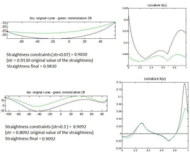
In Fig. 10 the two deformations of a curve are compared, first imposing a straightness constraint in the original way and then with the new convexity constraints; as it is shown, the imposition of such constraints prevents the creation of inflection points.
Fig.10: Increasing straightness with one position constraint, without convexity and derivative curvature constraints (on the top) and with convexity and derivative curvature constraints (on the bottom).
Note that in the example of Fig. 10. the solution is found obtaining a straight segment on the right of the curve; this should not worry: actually, imposing the constraints explained above, the optimization problem has to solve not strict inequalities and the straight line (if the straightness constraints = 1) or the straight curve segment (if straightness constraints is quite high) can be attained. With this method, it has been defined a deformation tool acting on the straightness property, while avoiding the appearance of new characteristic points.
4 CONCLUSIONS
The paper describes the definition and implementation of aesthetic properties suitable for design of styling products. Even if the defined measures do not discriminate univocally the curves, they satisfy the main purpose of formalizing the relationships between a change of their values and the corresponding resulting shape from an aesthetic point of view. Since the straightness property is a clear concept and widely accepted, it was considered here more into detail.
Actually, even if the here described tools act on 2D curves, they play a key role for 3D shape manipulation since they can support the qualitative modification of both structural features and details features (through the adjustment of the defining curve parameters) in 3D shape definition.
The future work concerns the implementation of the other aesthetic properties, such as tension, and sharpness, in order to allow an easier satisfaction of the designer's requirements. Finally, to achieve a more complete intent-driven design framework that better supports designer in the product shape manipulation, all these new modelling tools should be integrated in a unique feature-based modelling system, starting from the prototype developed in [3] and defining a completely new user interface naturally adhering the stylists way of working.
Moreover, since in the industrial design process it could be required to manipulate a set of consecutive curves (for example the curves constituting the profile of a car), the results should be extended to the manipulation of multiple curves; this requires an adaptation of the considered measures too. For some elements composing the measure, it could be sufficient to consider the sum of what obtained for the various curve components. In other cases, different elements should be considered, as for instance, for evaluating the straightness of several consecutive curves, the cord considered in the straightness measure is not the union of the various cords but it is the segment between the first extreme of the first curve and the last extreme of the last curve.
REFERENCES
[1] AIM@SHAPE (Advanced and Innovative Models And Tools for the development of Semantic-based systems for Handling, Acquiring, and Processing knowledge Embedded in multidimensional digital objects), European Commission Contract IST 506766 http://www.aimatshape.net.
[2] Bronsvoort, W. F.; Bidarra, R.; Nyirenda, P.: Developments in Feature Modelling, Computer-Aided Design and Applications, Vol. 3, N.5, pp.655-664, 2006
[3] Cheutet, V.; Catalano, C.E.; Pernot, J-P.; Falcidieno, B.; Giannini, F.; Léon, J-C.: 3D Sketching for Aesthetic Design using Fully Free Form Deformation Features, Computers & Graphics Special Issue: Sketch-Based Interfaces and Modelling, Volume 29, Issue 6 , December 2005, pp. 916-930 doi: 10.1016/j.cag.2005.09.009
[4] Cheutet, V.; Daniel, M.; Hahmann, S.; La Greca, R.; Leon, J.-C.; Maculet, R. ; Menegaux, D.; Sauvage, B.: Constraint Modelling for curves and surfaces in CAGD: a survey, International Journal of Shape Modeling 13 (2), 2007, pp. 159-199 . doi: 10.1142/S0218654307000993
[5] Cripps, R. J.: Quality Surface Construction, Journal of Prime Research in Mathematics,3(2007), 129-139.
[6] Farin, G.: Curves and Surfaces for CADCAM. 2nd ed. Academic Press, N.Y. 2002.
[7] Fontana, M.; Giannini, F.; Meirana, M.: A Free Form Features Taxonomy, Computer and Graphics Forum'99, vol. 18, N 3, pp. 107-118.
[8] FIORES-II Project, Character Preservation and Modelling in Aesthetic and Engineering Design, GROWTH Project GRD-CT-2000-0003, URL: http://www.fiores.com
[9] Giannini, F.; Monti, M.; Podhel, G.; Aesthetic-driven tools for industrial design, Journal of Engineering Design, 17 (3), 2006, pp. 193-215. doi:10.1080/09544820500275396
[10] Leyton, M. ; A Generative Theory of Shape, Lecture Notes in Computer Science, 2145, Springer, 2001.
[11] Pernot, J.-P. ; Fully Free Form Deformation Features for Aesthetic and Engineering Designs; PhD thesis, INP-Grenoble, IMATI-CNR, 2004.
[12] Pernot, J-P.; Falcidieno,B.; Giannini, F.; Leon, J.C.: Incorporating free-form features in aesthetic and engineering product design: State-of-the-art report, Comput. Ind. 59 (6) 2008. pp. 626-637 doi:10.1016/j.compind.2008.03.004
[13] Pernot, J.P.; Guillet, S.; Leon, J.C.; Falcidieno, B.; Giannini, F.: Interactive operators for Free Form Features manipulation, book of the SIAM Conference on Geometric Design and Computing, 10-13 November 2003, Seattle, USA.
[14] Piegl, L.; Tiller,W.:The NURBS Book, Springer Verlag, Berlin, 1996.
[15] Podehl G.: Terms and Measures for Styling Properties, Proceedings of the 7th International Design Conference, May 14th - 17th 2002, Dubrovnik, Croatia, pp. 879-886.
[16] Poldermann B.; Horvàth, I.: Surface design based on parameterized surface features, Symposium on Tools and Method for Concurrent Engineering (TMCE'95), 1995, pp. 432—446.
[17] Scheck, H. J.: Force density method for form finding and computation of general networks, Comp. Meth. in App. Mech. and Eng., 3 (2). 1974,pp. 115-134.
[18] Vergeest, D.S.M.; Horvath, I.; Spanjaard, S.: Parameterization of freeform features, Shape Modeling and Applications, SMI 2002 International Conference May 2002, Genova, Italy.