Technology researchers and makes it freely available over the web where possible.
This is an author-deposited version published in: https://sam.ensam.eu Handle ID: .http://hdl.handle.net/10985/11237
To cite this version :
Thierry PALIN-LUC, Serge LASSERRE - An energy based criterion for high cycle multiaxial fatigue - European Journal of Mechanics - A/Solids - Vol. 17, n°2, p.237-251 - 1998
Any correspondence concerning this service should be sent to the repository Administrator : [email protected]
Eur. .I. Mech.. A/Solids. 17, no 2, 237-251, 1998
An energy based criterion for high cycle multiaxial fatigue
Thierry PALIN-LUC and Serge LASSERRE*ABSTRACT. - In spite of the great number of high cycle multiaxial fatigue criteria in the literature, none predicts the difference that exists between the endurance limits in traction, four point rotative bending and four point plane bending. An energy based criterion based on a new concept using the strain energy density is proposed in this paper. This new calculation method explains the previous differences by taking into account the volumic distribution of the strain energy density around the considered critical point in fatigue. This method, available now under fully reversed multiaxial loadings, also takes into account the stress state triaxiality. Under combined plane bending and torsion the predictions of the new proposal lead to Gough and Pollard’s ellipse quadrant for ductile materials and lead to a curve close to an ellipse arc for brittle materials. Under other multiaxial loadings, predictions are always close to an ellipse quadrant dependent on the loading mode. This method has been tested on smooth cylindrical specimens with several materials; calculations are in very good agreement with multiaxial experimental data. 0 Elsevier, Paris
Kqwnrds. - High cycle multiaxial fatigue, criterion, energy. 1. Introduction
Many high cycle multiaxial fatigue criteria have been proposed in the literature and several studies have been devoted to a critical assessment of these criteria (Ballard
et al., 1995), (Bennebach, 1993) and (Papadopoulos, 1994) many references related to the criteria cited below can be found in these works. After a set of empirical formulae proposed by their authors to synthesize important fatigue test campaigns which were done at the end of the nineteenth century and in the first half of the twentieth century (Wohler, Haigh, Locati, Gerber, Gough and Pollard, etc.) the existing criteria in high cycle fatigue can be devided in three categories. The criteria of the first one are based on the following physical observation: after initiation, a fatigue crack propagates first along a shear plane. According to Miller and Zachariah (1977) this is the propagation first step; the second one is the crack propagation in a plane perpendicular to the maximum tensile principal stress direction. Since the aim of many high cycle fatigue criteria is to predict crack initiation (not propagation), many authors assumed that fatigue crack initiation was governed by the shear stress. Referring to this idea the following criteria can be cited: Stulen-Cummings, Findley, MC Diarmid, Sines, Crossland, etc. The criteria of the second set are based on the microscopic approach proposed for the first time by Dang Van in 1973. Since at a microscopic scale a metal is not isotropic nor homogeneous
* LAboratoire Materiaux Endommagement Fiabilite (LA.M.E.F) - E.N.S.A.M. CER de Bordeaux, Esplanade des Arts et Metiers, 33405 Talence Cedex, France.
EUROPEAN JOURNAL OF MECHANICS. A/SOLIDS. VOL. 17, No 2, 1998
0997-7538/98/02/O Elsevier, Paris
but is constituted from crystals of random orientation, Dang Van considers that fatigue failure do not occurs if and only if the response of the grains most unfavorably oriented and subjected to the microscopic fluctuations of the loading is elastic shakedown. Based on this assumption the following criteria were proposed: Dang Van, Papadopoulos and Deperrois for instances. These calculation methods research a critical plane containing the easiest slip direction of the crystals. Finally, other authors considered that crack initiation can be described by an energetic quantity exceeding a critical value: Ellyin, Glinka for examples. The criteria of this last category are based on the total strain energy density or the plastic strain energy density dissipated in the material. The main advantage of all the criteria based on a critical plane is to predict the crack propagation direction after initiation. The energy based criteria can not predict such a direction because energy is a scalar but these criteria use a simple macroscopic approach which do not need a long computation time to determine the critical plane.
However, none of the existing calculation methods predicts the well-known experimental differences which can be observed in all metallic materials between the endurance limits in traction, four point rotative bending and four point plane bending. Massonnet (1955) demonstrated this phenomenon with a 0.35% carbon steel in plane bending and rotative bending; Barrault and Lasserre (1980) showed the same behaviour with a 35CD4 steel. This means that the relation between predictions and experiments is not bijective. The endurance limit is dependent on the stress distribution in the mechanical part. Furthermore, in order to be in correct agreement with experiments, any high cycle multiaxial fatigue criterion has to be phase independent in combined plane bending and torsion (Papadopoulos, 1994) as shown by the experimental data of Simbtirger (1975) and Froustey and Lasserre (1989). According to the work of Simbtirger, however, the endurance limit seems to be phase dependent in biaxial traction (combined traction and internal/external pressure on thin walled tube). The aim of this paper is to present a new concept and a new criterion capable of predicting these observations and distinguishing load modes. At the moment the proposal is available under any fully reversed loadings; the effect of mean stresses is being studied now; variable amplitude loadings will be considered next. But it has to be emphasized that a bijective relation between predictions and experiments is looking for with this calculation method. Having justified the chosen energetic approach, its goal is to predict crack initiation and not crack propagation direc- tion, the basis of the new concept used to establish our proposal is presented. The proposed criterion is then developed, first for loadings involving uniaxial stress states and secondly for multiaxial conditions. A multiaxial stress state is defined with respect to the principal stress components. Finally, a comparison between test data and predictions is presented.
2. A new concept
By loading smooth specimens in blocks of plane bending and torsion alternatively applied until failure, at stress levels corresponding to the same life, Lasserre and Froustey (1992) found that fatigue life is the same as under plane bending loading alone or torsion alone. These authors show that several criteria based on the search of a specific critical
ENERGY BASED FATIGUE CRITERION 239
plane such as Sines, Crossland, Dang Van, Papadopoulos can not explain experiments with complex loading in blocks of different types (bending and torsion for instance). They proposed an energetic formula based on the accumulation of distorsion energy during a period of loading (Lasserre and Froustey, 1992). Bennebach’s tests (1993) in blocks of bending and torsion on a spheroidal graphite cast iron also show the same thing.
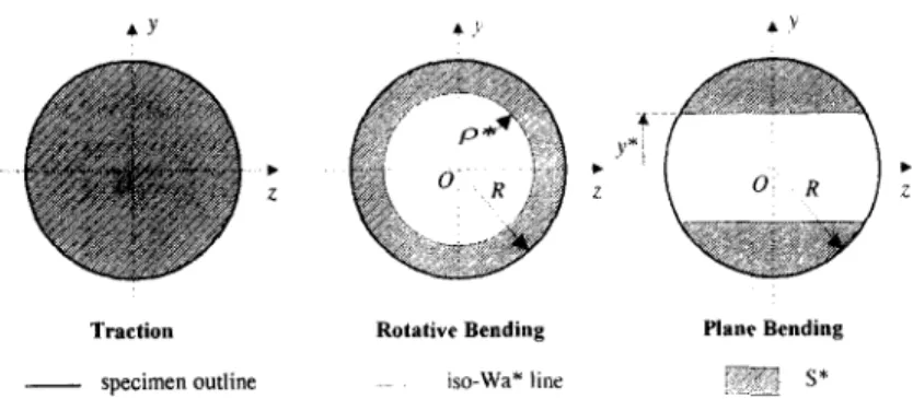
In a recent paper Papadopoulos and Panoskaltsis (1994) proposed a stress gradient dependent high cycle multiaxial fatigue criterion which predicts differences between plane bending and traction but not between rotative bending and plane bending. This proposal and all the others do not distinguish between these different loading modes because they only consider the tensor of stresses at the critical point and do not take into account the volumic distribution of stresses around this point. In Figure I we can see that the distribution of stresses at any moment is the same in plane bending and in rotative bending. In rotative bending, however, all the points lying on a circle centred on the middle of the specimen cross-section support the same stress during a cycle. In plane bending there is no axisymmetry, there are only two points supporting the greatest
Traction Rotative Bending Plane Bending
Wa b WaA WaA
Traction Rotntive Bending Plane Bending
Fig. I. - Stress distribution at a moment and Wa distribution on the cross-section of a smooth specimen loaded in traction, rotative bending or plane bending.
stresses. Considering a complete loading cycle such as proposed by Tsybanev (1994) permits to take into account this observation.
In their fatigue criterion, Froustey et al. (1992) have considered a complete cycle of stresses; our proposal is based on their work. They use the mean value on one cycle of the volumic density of the elastic strain energy, Wu, defined by (1) whatever the point M in the mechanical part.
where gij (M, t) and E~j (M, t) are respectively the tensor of stresses and the tensor of elastic strains at the considered point 1M function of time. Usually the endurance limit is low enough to consider that the material remains elastic at the macroscopic scale (Lemaitre and Chaboche, 1988). Thus, Wa can be considered as the mean value on one cycle of the total strain energy density at the considered point. Figure 1 illustrates the Wa distributions on the cross-section of a smooth specimen loaded in traction, rotative bending and plane bending. These distributions are very different. In order to take into account these differences we propose to consider a volume element around the critical point; this volume is defined below.
Experimental observations and data help us to define this volume. Vivensang and Gannier (1994) carried on SEM observations on smooth specimens in 35CD4 annealed steel loaded in four point rotative bending. They observed that persistent slip bands already exist after 50,000 cycles and microcracks after 300,000 cycles at the surface of smooth specimens loaded at their endurance limit. This means that the material is damaged (in terms of microcrack) even if it is loaded at its endurance limit without any macroscopic crack. Cumulative damage tests in blocks (Palin-Luc, 1996) and (Palin-Luc
et al., 1997) on a spheroidal graphite cast iron prove that blocks with stress amplitude equal to the endurance limit participate to damage if they are mixed with higher blocks. But, if the stress amplitude of low blocks is lower than a specific value the fatigue life is the same as if the amplitude of the low blocks were equal to zero. Furthermore, a constant amplitude load below this specific value creates no observable microcrack in the matrix of the cast iron. These studies show that another limit, called o*, can be defined below the usual endurance limit of the material, gD. At a considered point a stress amplitude below this new limit does not initiate observable damage at the microscopic scale (no microcracks). Between o* and oD a stress amplitude only contributes to the initiation of micro damage, which could develop if, either near this point or in the course of time, there is a stress amplitude higher than the endurance limit. The usual endurance limit is a limit of no damage propagation but it is not a limit of no damage initiation.
From g* and by analogy with a sinusoidal traction load the corresponding mean value of the strain energy volumic density, Wa*, can be calculated by (2), where
E
is the Young modulus of the material(2)
ENERGY BASED FATIGUE CRITERION 241
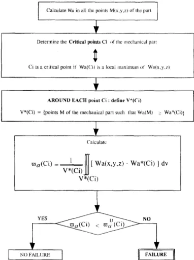
According to the Froustey and Lasserre criterion, the critical points C; with regard to fatigue are those where Wa is maximum. Around each point it is always possible to define the volume V* (C;) by the set of points M where Wa (M) is higher than Wa* (C;) (see 3). We postulate that the part of Wa (M) exceeding Wa* (C;) is the damaging part of the strain energy volumic density. From V* (C;), a, (C;) is defined by (4). wn (6’;) is the volumic mean value of the strain energy volumic density around the critical point C;. (3) V* (C;) = {points M (z, 9, ) z around C; such that Wn (M) 2 Wa* (C;)}
(4) w7, (G 3. Uniaxial stress
1
) = v* (C;)
JJJ
I-* CC*) [Wa (x, y, z) - Wu* (C;)] du statesAt the endurance limit and at the critical point C;, this new quantity a, (C,) is supposed to be constant, whatever the uniaxial stress state. If we note wg (Uniuz) its value at the endurance limit for any uniaxial stress state our criterion can be written by inequation (5). Failure occurs if this inequation is not verified.
(5) a, (C;) < a,: (Uniux) 3.1. EXAMPLES ON SMOOTH CYLINDRICAL SPECIMENS
To apply this criterion, the following parameters have to be identified: o*, Wu* (Uniuz) and a: (Uniuz). As there is no stress gradient along the longitudinal axis of a smooth cylindrical specimen, the volume V* can be reduced to the surface 5” inside the specimen cross-section, Eqs. (3) and (4) become:
(6) S* = {points M (2, y, z) around C; such that Wu (M) 2 Wu* (C;)}
(7) w, (G) = s* cci> 1
JJ
so (c,) [Wa (2, Y, 4 - Wa*(Cdl ds
The Wu distributions are axisymmetric in traction and in rotative bending (Fig. 1) and for this reason these two sinusoidal loadings are taken in reference to identify g*. In traction, all the points of the cross-section of the specimen have the same Wu value (Fig. 2), expression (7) becomes:
(8) Wu(Truc) = + * WC, (n-UC) = Wu (True)- wu* (Uniuz) = gTra& cr 2 *2 In four point rotative bending S* is a crown, the iso-Wa lines are circles as shown in Figure 2. For such a loading on smooth cylindrical specimens w,, is given by (9) where
(TX~,~B~,,,~ is the maximum stress due to rotative bending on the cross-section and p* is the radius of the circle representing the iso-Wa* line (Fig. 2).
(9) Wa (R&Bend) = “kdhrl .r2 4E,R’
+ wc, (C;, RotBend) = ““~~lld.(1-(~)2) ifp*<R
At the endurance limit, wj, (C;) is supposed to be constant whatever the uniaxial stress state at the critical point C; : w: (Trac) = w: (C;! R&Bend). Thus equation (10) is obtained from (8) and (9); it is a convenient expression for design purposes. From (2) and (8) it is easy to prove that Wa* (Uniaz) is given by (11); wf (Urr,l;a,z) can be calculated by (12).
(12)
Equation (10) is only available if (T&~~,,,~~/@~,,,~, < &; according to the authors this condition is true on all metallic materials, usually this ratio is less than 1.3 (Papadopoulos and Panoskaltsis, 1994). u&+,,,~ can be considered as a material parameter if the radius of the specimen is larger than about 5 mm as shown by Pogorotskii and Karpenko (from Papadopoulos and Panoskaltsis, 1994).
Traction Rotativc Bending Plane Bending
- specimen outline iso-Wa* line m, [ ,?A s* Fig. 2. - Iso-Wa lines and S’ surfaces on the cross-section
of a specimen loaded in traction. four point rotative bending or plane bending.
ENERGY BASED FATIGUE CRITERION 243
3.2. PREDICTION IN FOUR POINT PLANE BENDING
The iso-Wa lines are straight lines parallel to the neutral fibre of the cross-section (Fig. 2). Expression (13) can be deduced from (6) and (7), where CJplBrn(/ is the maximum stress on the cross-section due to plane bending and ?J* is the ordinate of the iso-Wa* line (Fig. 2).
(13)
Wa (Pl Bend) = g~~n&‘2 + wLJn (C;, PIBend) = w. 2 {A(a) - N’}
7x-
where CI = x
--!!(Q-
i and A (a) = ’ r 1) &T2 - $ arcsin ck --
2 a J!iT7 - arcsin Q
According to the previous hypothesis, W: (Uniaz) = wf (C;, PIBend). By noting y = c+?lBrnd/&,tBend the ratio we are looking for, this ratio is solution of Eq. (14) where A (z) is the function defined by (13).
wf (Uniax) = a: (C;, PiBend) (14)
e 272.A(t3+324=”
where
4. Multiaxial stress states
The influence of the triaxiality of stresses on the endurance limit has already been shown in a number of studies: Galtier and Seguret (1990) for instance. We propose to take into account this influence by using the F function defined by Froustey et al.
(1992). By referring to the work of De Leiris (1969) these authors define the degree of triaxiality, dTa, for a fully reversed loading by expression (15) where Wsa and Wda
are respectively the spherical part and the deviatoric part of the strain energy volumic density (16). For any periodic loading it is easy to prove that Wa = Wsa + Wda.
(15)
dTa = WsaWsa + Wda
(16)
wsa= (?..j$!) $ LT &(t)dt and Wda= (F) f iT
rJxo(t)dt
where 11, (t) = ~.k (t) and J2 n (t) = $ s;,j (t) s;) (t) by noting a;j (t) = ~ ' 6ij + ";j (t).
Based on many experimental data in high cycle fatigue, Froustey et al. (1992) have proposed to relate, at the endurance limit, the value of Wa (C;, load), whatever
the loading, to the value of Wn in Torsion, Wa (C;? Tars), by the function F
(see 17) depending on the degree of triaxiality of the stresses at the critical point
C;, dTa (C;, load), and a new material dependent parameter p.
(17) F(dTa(C;, load), ,#) = ;$;z’;;rt))
1 .{I-$n[i+dTa(C;Joad)+?-I)]} = 1 - dTa(Ci, load)
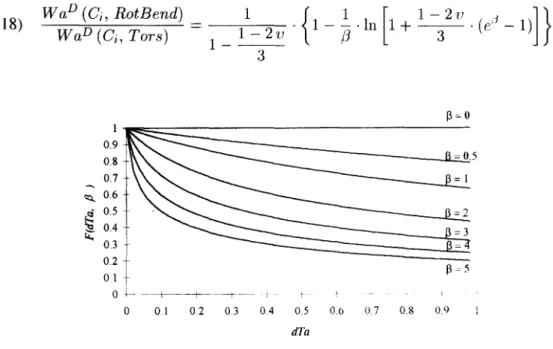
The ,O parameter is representative of the material triaxiality sensitivity. io, is equal to zero for a XC 18 annealed steel and is around 3 for a spheroidal graphite cast iron. Evolution of the function F is illustrated by Figure 3. The identification of the ,6 parameter has to be done by applying Eq. (17) with the endurance limits in Rotative Bending and in Torsion. It becomes (18) where the only unknown is ,/?; u is the Poisson ratio. The endurance limit in torsion is the only other experimental data needed to apply this approach.
(18) WaD (C;, RotBend) WaD (Ci, Tom) = 1 _ 1 - 271 l .{l-j-ln[l+y.(e”-l)]} 3 1 0.9 0.8 0.7 ; 0.6 6 0.5 6 0.4 G 0.3 0.2 01 B = 0.5 015 t 0 1.. --t---f- +-- i I 0 01 02 03 04 0.5 0.6 07 0.8 0.9 1 dTa
Fig. 3. - Evolution of the function F
In order to take into account the triaxiality influence we suppose that Wa* is loading dependent and verifies Eq. (19). It can be noted that in traction, rotative bending and plane bending, dTa (Ci, load) is the same and so Wa* has the same value. With (19) Wa* is defined whatever the loading, so V* is also defined.
(1%
Wa* (Ci, Tom) Wa* (C; , load) = F (dTa(C;, load), p)ENERGY BASED FATIGUE CRITERION 245 The influence of triaxiality has also to be taken into account in the definition of the limit value of r$ (C;). By analogy with the previous assumption, we postulate that for any loading at the endurance limit the value of a: (C;), noted r$ (C;, load), verifies (20).
‘2oJ
W([ (Ci, load) = F (dTa (C;, loud), p> * P; (C;, load) = F (dTu (Ci, loud), ,#) a,? (C;, Tom) W(f (Uniuz) F (dTa (Uniux), /?) With this last point the criterion can be applied on any fully reversed loading. Its use can be summarized as described below.
Use of this proposal
Two static characteristics of the material are necessary: E and U. Only three experimental endurance limits under fully reversed loadings are needed: the endurance limit in traction, (T$~,,,, the endurance limit in rotative bending, criOtBc,nd and the endurance limit in torsion, r&. From ~$OtB~lLd and rT,, D the /‘Jl material parameter is identified by solving Eq. (18). At the endurance limit on any mechanical part, the terms of the stress tensor are solutions of Eq. (20). In this equation a,? (C;, Zoud) is defined by:
(21)
a,? (Ci, loud) = -A-.-
v* (Cd
JJJ
1-
* *
(c ) VW?
9, 2, Zoad)
- Wa
* (C;, loud)] du (G, zo4)where V” (Ci) = {points A4 (2, 9, z) such that Wu (M) 2 War and Wu* (C;, Zoud) = Wu* (Uniuz) F (dTu (C;, loud), p) F (dTu (Uniax), 0)
The use of this criterion in a design department can be synthesized as shown in Figure 4. 5. Application of the criterion under combined loadings
The predictions of our proposal are presented below for several combined loadings usually used in laboratory tests. Calculations are detailed in combined rotative bending and torsion. For the other combined loadings: plane bending and torsion, traction and torsion, biaxial traction on thin walled tubes (traction and internal/external pressure) final results only are presented.
5.1. COMBINED ROTATIVE BENDING AND TORSION ON SMOOTH CYLINDRICAL SPECIMEN
On a smooth cylindrical specimen loaded at its endurance limit (~&BPnd+~O, 7n4,tBcr,d+To) with ~Rg,,tBrlld+Tu/7RDotB~~~+T” = k the Wu distribution on the specimen cross-section is given by expression (22).
2
(22) W,, (RotBend + To) = i
0 [
. (dk?d+To 4E ) 2 + ( D rRotBr,rrl+TO)I
2 EllROPEAN JOURNAL OF MECHANICS, A/SOLIDS.VOL. 17, No 2, I998Calculate Wu in all the pomts M(x.y,~) of the pall
AROUND EACII point Ci : define V*(Ci)
V*(Ci) = {points M of the mechanical par, such thar Wa(M) : Wa*(Ci))
I ma(Ci) =- ill [ Wa(x,y,z) - Wa*(Ci) J dv V*(Ci) V*(Ci)
Fig. 4. - Synoptic of our proposal for use in a design department
The Wa* (Ci) va ue in combined Rotative Bending and Torsion is given by: 1
(23)
W,* (C, , RotBend+To) = 2 <4Ylc)2 - bRDootBrnJ 4E . F (dTa (C;, RotBend + To), p) F (dTa (Uniaz), ,O)
So by using (22) and (23) it is easy to prove that the T* radius of the circle on the cross-section representing the iso-Wa* line is given by:
(24) 2
2 GL)” - (~RDotBwJ
= ((T&.jrnd+To)2 . (1-t 2. (1 + u)/k2) .
F (dTa (Ci, RotBend + To)! [j) F (dTa (Uninz), /3)
ENERGY BASED FATIGUE CRITERION 247 From its definition (21) z~f (Ci, RotBend + To) is given by the following expression
(25):
(25) rn: (C;, RotBend + To) = oXuf~~+To ’ (I+ ’ (lkT ‘I)) c 2 k%cF GootBwJ2 . F(dT u (L:R 0 tBend:To) p)
I
8E F (d;lu (Uniaz), /3) , -Wa* (C;, RotBend+To)
and its value is defined by expression (26).
(26)
rn: (Ci, RotBend+To) = (cJ&~~,,~~)~ - (c&.)~ . F (dTa (Ci, RotBend + To), P) 4E F (dTa (Uniuz), /?)
From (25) and (26) and by using (23) the endurance limits (a&Bi,,,ll+To: $&Bi,,,,+70) can be calculated. They are given by (27) whatever the ratio k.
(27)
D
~RofBmffTo
=
J1 + 2 (1 + qp .
~~RDofBe,,d)2 F (dTu (C;, RotBend + To); p)F (dTu (Uniuz), /3)
D D
7RotBrr,d+To = ~RotBd+To if
These predictions are phase independent because the degree of triaxiality is not phase dependent.
(28) dTu (Ci, RotBend + TO) = (1 - 2v). k”
3 . k” + 6. (1 + U)
Furthermore, these predictions lie on a curve all the closer to the Gough et al. (195 1) ellipse quadrant, (~~~t~~~tl+~~/(rRDutBe,ld)2 + (~~Ot~l,nd+~o/~~Oo)2 = 1, than the P parameter is close to zero (ductile material). ,Lj’ is all the more different from zero than the material is brittle; in this case the predictions are close to the Gough et al. (1951) ellipse arc.
5.2. OTHER COMBINED LOADINGS
5.2.1. Plane bending and torsion, traction and torsion
The results derived from our approach are dependent on the mode of loading; its predictions are different for each of these combined loadings, as illustrated by Figure 5. This method leads to three curves close to ellipse quadrants which are not phase dependent. This is in agreement with experiments.
5.2.2. Biaxial traction on thin walled tube (traction and internal/external pressure)
The longitudinal stress is CJI sin w t and the hoop stress is CTh sin (w t + cp) with q/q1 = A. It must be pointed out that in biaxial traction on a thin walled tube the degree of triaxiality defined by (15) is phase dependent (see 29). Under this loading the endurance limits predicted by the criterion are phase dependent (30). They lie on a curve close to an ellipse arc as shown in Figure 5.
(2% dTa (C;, BinzTmc) = (Lg).( x~-2.Wx~coscp+1 x”+2.x~coscp+l
>
(30) ap = cJ&,( 1 + l/P - 2 (w CO8 cp)/X . 1 F (dTa (C;; BicmTrac), j3) F (dTa (Uniaz). /3) and ~7; = $
~. ~~ Plane Bending + Torsion Rotative Bending + Torsion * ~~~.._ Traction + Torsion
normal stress amplitude
0 0.1 0.2 0.3 0.4 0.5 0.6 0.7 0.8 0.9 1 1.1 longitudinal endurance limit I traction endurance limit
Fig. 5. - Predictions of the criterion in combined loadings and phase influence in biaxial traction.
ENERGY EASED FATIGUE CRITERION 249
6. Comparison between experiments and predictions
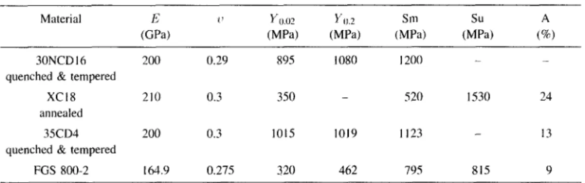
In order to test the accuracy of the predictions of our proposal, the comparison between experiments and predictions has been made for four materials and 14 experimental endurance limits on smooth cylindrical specimens. The materials are: a 30NCD16 quenched and tempered steel (Froustey and Lasserre, 1989), a XC1 8 annealed steel (Lasserre and Froustey, 1992), a 35CD4 quenched and tempered steel and a spheroidal graphite cast iron (AFNOR standard close to FGS800-2) (Bennebach, 1993) and (Palin-Luc, 1996). Their mechanical characteristics are given in Table I.
TABLE 1. - Static mechanical characteristics of the tested materials. Material E (GPa) y0.02 YlJ.2 WPa) (MPa) Sm (MPa) (MPa) su (8) A 30NCD 16 200 0.29 895 1080 1200 -
quenched & tempered
XC18 210 0.3 350 - 520 1530 24
annealed
35CD4 200 0.3 1015 1019 1123 13
quenched & tempered
FGS 800-2 164.9 0.275 320 462 795 815 9
b’=Young modulus, o=Poisson ratio, Y u.u2=Yield stress at 0.02%. Ynz=Yield stress at 0.2%, Sm=Maximum tensile stress, Su=Ultimate tensile stress, A=Elongation at failure.
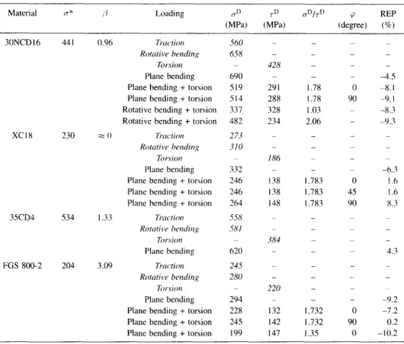
For an objective and easy comparison the Relative Error of Prediction of the criterion, REP, is defined by (31).
(31) x 100
All the REP are shown in Table II with the experimental data. The Table II proves that our criterion is in very good agreement with experiments. The absolute value of the REP is always less than 10%. Since crack propagation is not taken into account in the proposed criterion test results have to be relative to crack initiation detected as soon as possible with today experimental set up; for instance 0.5 mm in depth for a 12 mm diameter specimen with our multiaxial fatigue testing machine (Palin-Luc and Lasserre, 1994).
The values of o* given in Table II show that the ratio CT*/C$~~,~ varies between 0.7 and 0.9 for the five tested materials; we have not enough experimental data to generalize this observation.
7. Conclusion and prospects
This high cycle multiaxial fatigue criterion is the first to predict the experimental differences between traction, rotative bending and plane bending. These differences are
TABLE II. - Experimental results and relative error of prediction, REP, of the criterion. The values in italics are used to identify the different parameters (T* and /j of the criterion
Material (+: :I Loading n” +I cTD/TD (3 REP
(MPH (MI%) (degree) (96) 3ONCDl6 441 XC18 230 35CD4 FGS 800-2 534 204 0.96 T~lKtiO~l Rot&w bending TOr:SiOH Plane bending Plane bending + torsion Plane bending + torsion Rotative bending + torsion Rotative bending + torsion
;=: 0 hction
Rotutive hrndir,,~ Tor.Gorr Plane bending Plane bending + torsion Plane bending + torsion Plane bending + torsion
I .33 Trodon Rotrrtilv hmtling Tu,:c-ion Plane bending 3.09 Trnctim Rotati\,r hmding krsiorl Plane bending Plane bending + torsion Plane bending + torsion Plane bending + torsion
560 658 690 519 514 337 482 273 3/O 332 246 246 264 558 5x/ 620 245 280 294 - 228 132 245 142 199 147 - - 428 - 291 288 328 234 - 186 - 138 I38 I48 .3t(4 - - - 220 - - - - 1.78 I .78 1.03 2.06 - - - I .783 1.783 I .783 - - - - - - - - 1.732 1.732 I .35 - - 0 90 - - - 0 45 90 - - - - 0 90 0 - - -4.5 4.1 -9.1 4.3 -9.3 .- -6.3 I .6 I .6 x.3 - 4.3 - - -9.2 -7.2 0.2 -10.2
explained by the volumic distribution of the mean value on a cycle of the strain energy volumic density. Fully reversed loading modes are distinguished with this approach. The predictions of this criterion are in very good agreement with uniaxial and multiaxial experimental data on smooth cylindrical specimens in several materials. The criterion takes into account the difference between ductile and brittle materials by the ,/3 parameter. In the future the development of this method on notched specimens will be done by using the finite elements method to take into account the volumic distribution of the strain energy density around the notch. It is also necessary to take into account the influence of a mean value in a loading before this criterion can be adopted for design purposes. Nevertheless the capabilities of this method are very promising.
Acknowledgements
This work was carried out as part of a research contract with the Materials Engineering Department of Renault. Renault is gratefully acknowledged for enabling the authors to do this work.
ENERGY BASED FATIGUE CRITERION 251
REFERENCES
BALLARD P., DANG VAN K., DEPERROIS A., PAPADOPOULOS Y. V., 1995, High cycle fatigue and finite element analysis, Fatigue Fract. Engng. Mater. Struct., 18, No. 3, 397-41 I.
BARRAULT J., LASSERRE S., 1980, Limites de fatigue de I’acier 35CD4 en flexion rotative et en flexion plane.
Rev. Mecanique Materiaux et Electricire, Sept., 275-218.
BENNEBACH M., 1993, Fatigue d’une fonte GS. Influence de l’entaille et d’un traitement de surface, Ph. D. thesis, ENSAM CER de Bordeaux, France, 157 p.
De LEIRIS H., 1969, TriaxiaIitC des contraintes et critere de non fragilite, Bulletin de I’Associution Technique Maritime Aeronautique, 48 l-49 1.
FROUSTEY C., LASSERRE S., 1989, Multiaxial fatigue endurance of 30NCDl6 steel, ht. J. Fatigue, 11, No. 3, 169-175.
FROUSTEY C., LASSERRE S., DUBAR L., 1992, Validite des crittres de fatigue multiaxiale a I’endurance en flexion-torsion, Mat-Tech Y2, 79-85, IITT-International, France.
GAI~TIER A., SEGURET J., 1990, Criteres multiaxiaux en fatigue : exploitation en bureau d’etudes. Proposition d’un nouveau critere, Rev. Fran@se Me’canique, No. 1990-4, 291-299.
COUGH H. J., POLLARD H. V., GLENSHAW W. J., 1951, Some experiments on the resistance of metals to fatigue under combined stresses, Aeronaut. research council reports und memorunda, 141 p., London.
LASSERRE S., FROUSTEY C., 1992, Multiaxial fatigue of steel-testing out of phase and in blocks: validity and applicability of some criteria. Int. J. Fatigue, 14, No 2, 113-120.
LEMAITRE J., CHABOCHE J.-L., 1988, Me’canique des maferiaux solides. Ed. Bordas, Paris, 544 p.
MASSONNET Ch., 1955, Le dimensionnnement des pieces de machines soumises a la fatigue. Contribution experimentale B l’etude de I’effet de l’echelle et des entailles. Rev. Univ. Mines, Paris, 9, T. XI, No. 6, 204-222.
MILLER K. J., ZACHARIAH K. P., 1977, Cumulative damage laws for fatigue crack initiation and stage I propagation, J. Strain Analysis, 12, No. 4, 262-270.
PALIN-LUC T., LASSERRE S., 1994, Multiaxial fatigue testing machine under variable amplitude loading of bending and torsion. In Recent Advances in Experimental Mechanics, J. F. Silva Gomes et al. ed., Balkema A. A., Rotterdam, 965-970.
PALIN-LUC T., 1996, Fatigue multiaxiale d’une fonte GS sous sollicitations combinees d’amplitude variable. Ph. D. thesis, ENSAM CER de Bordeaux, France, 261 p.
PALIN-LUC T., LASSERRE S., BBRARD J.-Y., 1997, Damage evolution of a spheroidal graphite cast iron loaded around its endurance limit. In Proc. 5th Eur. ConjI on Advanced Materials and Processes and Applications,
SARTON L. A. J. L. and ZEEDIIK H. B. ed., Netherland Society for Material Science, Zwijndrecht, vol. 1,
511-514.
PAPADOPOULOS I. V., 1994, A new criterion of fatigue strength for out-of-phase bending and torsion of hard metals, Int. J. Fatigue, 16, No. 6, 377-384.
PAPADOPOULOS I. V., PANOSKALTSIS V. P., 1994, Gradient dependent multiaxial high-cycle fatigue criterion, Proc. 4th Int. Co@ Biaxial/Mulfiaxial Fatigue, SF2M, St-Germain-en-Laye, France, Vol. 1, 461-476.
SIMBURGER A., 1975, Festigkeitsverhalten zlher Werkstoffe bei einer mehrachsigen, phasenverschobenen Schwingbeanspruchung mit kdrperfesten und verlnderlichen Hauptspannungsrichtungen. Laboratorium fur betriebsfestigkeit, Darmstadt, Germany, Bericht, Nr. FB-121, 89 p.
TSYBANEV G. V., 1994, An energy approach to fatigue tests and crack initiation stage determination. From
Problemy Prochnosti, Ukranian Acad. Sci., Kiev. Plenum Publishing Corp., 2, 12.27.
VIVENSANC M., GANNIER A., 1994, Testing and microstructural interpretation of 35CD4 steels in cumulative high cycle fatigue damage. In Recent Advances in Experimental Mechanics. J. F. Silva Gomes et ul. ed., Balkema A. A., Rotterdam, 1107-l 112.
(Manuscript received January 13, 1997; revised November I I, 1997).