Science Arts & Métiers (SAM)
is an open access repository that collects the work of Arts et Métiers Institute of
Technology researchers and makes it freely available over the web where possible.
This is an author-deposited version published in: https://sam.ensam.eu
Handle ID: .http://hdl.handle.net/10985/9937
To cite this version :
Jean-Edouard DESAIGUES, Christophe LESCALIER, Anne BOMONT-ARZUR, Olivier BOMONT
- High Strength Steel solutions for automotive parts : State of the art of machinability
enhancement and further developments - In: Tenth International Conference on High Speed
Machining, Allemagne, 2013-09-26 - Proceedings of the Tenth International Conference on High
Speed Machining - Progress in Productivity and Quality - 2013
High Strength Steel solutions for automotive parts:
State of the art of machinability enhancement and further developments
J.E. Desaigues1,2, C. Lescalier2,
A. Bomont-Arzur1, O. Bomont2
1ArcelorMittal Long Carbon R&D – Gandrange Bars & Wires, Gandrange, France 2Arts et Métiers ParisTech – Centre de Metz, Metz, France
Abstract
For many decades ArcelorMittal has been developing solutions to enhance machinability of high strength steels for automotive parts. Many well-known metallurgical solutions create or retain inclusions in the metal and then promote machinability without decreasing the mechanical characteristics. Such metallurgical treatment usually leads to the formation of so-called Built-Up Layers (BUL) or transfer layers on the cutting tool while machining. The tool wear rate decreases and thus allows a longer tool life or a better productivity. The existence of such BUL on the cutting tool depends on many parameters i.e. tool geometry, tool material, cutting parameters… There is a growing need in the automotive industry for lighter parts. This has led to a global trend to develop new steel grades with higher mechanical properties. ArcelorMittal is currently developing new metallurgical solutions to optimize steel grades to ensure a better machinability thus preventing productivity losses. BUL characteristics are being studied for the most important machining operations. This paper summarizes the main developments in steel machinability for many decades. Some results from research works into turning and drilling highlight the benefits of these new steels.
Keywords:
Machinability, Super High Strength Steels, Built-Up Layer
1 INTRODUCTION
Machining and grinding are material removal processes devoted to produce finished workpieces. Machining often accounts for a substantial fraction of the total workpiece cost (up to 65%). This is why machinability is thoroughly investigated by steelmakers. This paper focuses on long carbon products used in automotive industry. Market studies highlight two steel families: free-cutting steels and High and Super High Strength Steels. A bibliographic survey shows that almost 40% of machinability studies focused on metallurgical problems deals with free cutting steels while 60% deals with construction steels. Nowadays, new steel compositions are proposed to reach higher yield stress and tensile stress while saving costs. This trend leads to micro and low alloyed steels with bainitic structure. Machinability should therefore be lowered compared with usual quenched and tempered steels. Solutions are to be found to enhance it. This review summarizes the usual metallurgical solutions used by steelmakers to improve the machinability. New solutions for the machinability improvement are currently expected to answer the new customer’s requirements for construction steels as well as high strength steels. The paper also proposes some relevant results from research work performed in turning and drilling.
2 MACHINABILITY
Machinability is fully dependent on the cutting process. The results cannot be roughly adapted from process to process [1], [2]. Four criteria usually describe machinability i.e. cutting forces, surface quality, chip shape and tool life. Some may be added to better describe the mechanical phenomena involved in metal cutting i.e. the apparent friction coefficient or the cutting temperatures. For steelmakers, improvements in machinability are in most of cases associated with metallurgical treatments which have an impact on the following items:
Reduction of the friction coefficient at both of the tool’s interfaces,
Improvement of the surface quality and dimensional tolerances,
Improvement of the chip breakage, Increase in tool life.
These machinability improvements usually depend on interactions between the tool and the chip when cutting.
3 STEEL SOLUTIONS FOR MACHINABILITY
From the steelmaker’s point of view, machinability can be enhanced by:
1. The addition of non-metallic and metallic miscible elements in steel such as Mn, S, Se...
2. The addition of metallic and non-metallic immiscible elements in steel such as Pb, Bi, Te.
3. The reduction of the number of hard particles which leads to the decrease of the steel abrasiveness during machining but requires the optimization of the steelmaking process.
Depending of their composition – and thus their melting point - non-metallic inclusions will appear and solidify at several moments during the steelmaking process. The knowledge of their composition, constitution and occurrence is essential if their detrimental effects are to be minimized and their positive effects used [3].
It is generally assumed that metallurgical treatment can improve the machinability by:
Improving chip breakability, for example through Liquid Metal Embrittlement (LME).
Limiting the formation of a Built-Up Edge (BUE). Creating a Built-Up Layer (BUL).
Figure 1: Schematic drawing of the behaviour of various types of inclusions during machining (after [4], [5]) A delicate balance between the deoxidisation elements used and the resulting inclusion population is required to achieve the optimum combination of machinability and tool wear.
3.1. Sulphur (S) – sulphides
After oxygen, sulphur is the most important non-metallic element in steelmaking practice. The main part of sulphur is combined with manganese, forming MnS inclusions. The other principal sulphide inclusions types are FeS and (Mn,Me)S (Me as metal) [6]. It has been known for many decades that MnS inclusions can enhance machinability. Scientific studies on this topic have been undertaken only since the end of the 60s. There are two opposite trends in the steel development process. The first is to produce a steel grade with the lowest possible sulphur content and then ensure the highest notch toughness. The second is to increase the concentration in sulphides to improve machinability and retain notch toughness. The most relevant solution to limit the sulphides concentration in steel while increasing machinability consists in optimizing the sulphides morphology. Before hot rolling, sulphides are spheroidal due to their solidification in the liquid metal. The melting point of pure MnS is about 1600°C. Sulphides in steel contain oxides (FeO, MnO, SiO2) and
FeS which decreases the melting temperature under the steel liquidus (around 1500°C).
MnS size in the work material
The size of sulphides has supposedly a major influence on machinability improvement. A few big MnS inclusions seem more efficient than numerous small ones [6], [7]. In substance, these results don’t explain the influence of the MnS size on a lubricating effect in machining.
Built-Up Edge (BUE) is usually considered as detrimental for machining. It is supposed to occur at low cutting speed and progressively disappear when cutting speed increases. Several authors have found that larger MnS inclusions may reduce the BUE appearance at low cutting speed [8], [9]. However, the mechanisms leading to these results are not well known. Some studies have shown that the size of MnS is directly linked to the cooling rate in continuous casting. When the cooling rate is lower, MnS can grow for a longer time. It may explain why MnS inclusions are bigger when steel comes from blooms rather than from billets.
Figure 2: Relationship between machinability and number of sulphide inclusions in free-cutting steel. There is a constant volume fraction of MnS in the steel. In this way,
the larger the sulphide particle size (i. e. the smaller the number of sulphides) the better the machinability (after [7]). MnS action on machinability
The contact length on the rake face of the tool is shortened by the presence of MnS [10], [11]. The separation of the chip from the tool on which it is sliding requires fracture. The shorter contact length results in thinner chips and lower cutting forces. It is also possible that, in this form, they may provide surfaces of easy flow where the work done in this shear zone is less than it would be in the body of the metal [10]. In this way, sulphides can act as internal lubricant, promote chip breakage and can also lead to the transfer of MnS layers on both rake and flank faces of the cutting tools [5]. These effects are particularly noticeable for free-cutting steels rather than for construction steels because of their higher sulphur content.
Selenium
Selenium (Se) inoculates the MnS inclusions. The melting point of Se is low (217°C at 1 bar). This element changes the visco-plastic behaviour of the MnS inclusions. During hot rolling, MnS inclusions are more resistant to the deformation and therefore become less elongated. On the final product, MnS have a more globular shape. Kiessling [6] has studied the influence of Se and found that the MnS inclusions become larger and more globular through Mn(S,Se) formation. The usual Selenium content in these steels is ~ 0.02 to 0.04%. However selenium is regarded as a toxic element. Steelmakers usually avoid it to preserve worker’s health.
3.2. Pb / Bi / Te
Lead (Pb) and bismuth (Bi) can be added to enhance machinability and surface roughness. Both of these elements are heavy metals and induce liquid metal embrittlement with its consequences on chip breakage, lubricating effect at the tool/chip and tool/work piece interfaces leading to the decrease of the cutting forces. These phenomena are mainly due to their physical properties: Pb and Bi are both immiscible elements in the steel matrix. Both have a low melting point: 327°C for Pb, and 271°C for Bi at 1 bar.
The main differences between Pb and Bi are:
For the same gain in machinability, Pb content is three times higher than Bi (for example: 0.3% Pb compared with 0.1% Bi).
The hot forming of Bi steels is problematic because of the LME at grain boundaries under hot rolling temperatures [5].
The cost of bismuth and the very low number of suppliers can also be an issue. In May 2013, the average cost of Bi pure element was 15,31 € per kg while pure Pb was about 1,70 € per kg. Bi is then about 9 times more expensive than Pb.
Tellurium (Te) can be added alone or in association with Pb and/or Bi. Te’s melting point is 450°C at 1 bar. Te surrounds the sulphide inclusions, as Pb and Bi do. Oxides and tellurides play an essential role in hot rolling. Having a thin form at the inclusion/matrix interface, these phases behave as a lubricant which, by reducing the friction stress, reduces the deformability of sulphides. In addition, as in the case of Selenium, the MnS inclusions become less plastic through the Mn(S,Te), resulting in less deformation during hot rolling. This is explained by the fact that there is a small solid solubility of Te in MnS [6]. This leads to more globular inclusions in the steel and a better machinability. The Te content must be lower than 0.030% to prevent surface defects occurring during hot rolling [5], [6], [12], [13].
3.3. Oxides
Oxide inclusions are often considered as detrimental for many properties of steel. Because of their high hardness, they are assumed to be a huge source of possible nucleate cleavage cracks [6], then decreasing many mechanical characteristics of steel, such as ductility, toughness, and fatigue resistance [14]. In reason of their high melting point, they can already be solid during the steel making process. Important inclusion phase are corundum, escolaite, spinels and the calcium-aluminates [6]. The main difficulty is to avoid or to limit as well as possible the presence of sharp-edge hard oxides such as Al2O3. At the contrary, the presence of malleable oxides
can lead in some cases to an improvement of machinability (especially, inclusion within certain composition ranges in the MnO-SiO2-Al2O3 and
CaO-SiO2-Al2O3 systems). Special metallurgical treatments
conduct to such results. A typical example, well encountered in the case of construction steels, is the calcium treatment. Kiessling describes the effects of a calcium treatment on Al-Si deoxidized steels, explaining that the usually encountered inclusion compositions are in the area I and II respectively (see figure 3), depending on the Al and Si levels. An addition of Ca makes the composition of the inclusions evolve. This change is done following the direction of the arrows. Some “new” inclusions appear (area III and IV respectively).
The principle leading to this phenomenon is almost the same as with sulphides: a good deformability in the primary shear zone allowing a better chip fragmentation and a lubrication which reduces the increase in temperature at the tool/chip and tool/work material interfaces [15]. As an additional result, the inclusion’s hardness and so abrasiveness decreases leading to a longer tool life.
Figure 3: Influence of calcium treatment on the inclusions in the system CaO-Al2O3-SiO2 (after [16])
4 BUILT-UP LAYER (BUL)
4.1. Definition
It is commonly assumed that so-called Built-Up Layer (BUL) or transfer layers are formed by plastically deformable inclusions which soften at the contact zone between the tool and the steel (see figure 4). The BUL and the BUE (Built-Up Edge) are quite different, since the selective transfer mechanism is done inside the flow layer, the thickness of the MnS layer stuck on the tool face is fairly constant (for given cutting conditions), and much smaller than a Built-Up Edge. In this case, there is no space between tool face and chip bottom, and all of these features correspond to the definition of the BUL (CIRP Unified Terminology, 1986) [17].
Figure 4: Built-Up-Layer formation on the tool during the cutting operation
4.2. BUL domain of existence and BUL thickness A BUL can be described in many ways: composition, structure, thickness... Many authors show that BUL depends on many parameters (cutting parameters, work material, tool material, cutting time, tool wear…). However, for a given tool and a given work material, the only parameters should be the cutting speed, the cutting feed, the cutting depth and the cutting time. Many studies highlight that BUL’s thickness will evolve with the cutting speed: BUL starts to appear when the BUE disappears, the thickness then reaches a maximum (up to 30 µm [18]–[20]), and then progressively decreases.
4.3. BUL Localization and structure
Several authors have already studied the morphology of BUL when machining several kinds of steel [13], [15], [19]–[21]. It is therefore difficult to bring out global trends. However, many assumptions can be made.
BUL are mostly observed on the rake face and the flank face of the tool, even if strong differences appear between layers from the rake and the flank face, as reported [13], [18], [20]. On the rake face, it is often observed experimentally that the BUL is spread in the Chip Flow Direction and is located at the centre region and the exit region of crater wear [22].
The morphology of the BUL depends on many factors, especially tool geometry and the possible presence of a chip-breaker. It is indeed often described in the literature that the deposit layer doesn’t entirely cover the rake face and appears irregular and non-uniform at the end of the tool/chip contact zone [13] when using a cutting insert with a chip-breaker (which is the case for most of the modern cutting inserts). At the contrary, the use of a cutting insert without chip-breaker leads to a more regular BUL which covers continuously the rake face of the tool. In this way, a huge number of undertaken studies on BUL were performed by using cutting inserts having no chip-breaker, which overcomes the geometry of the tool. Layers on the flank appear generally thinner and more scattered than at the rake. It has also sometimes been found differences in terms of chemical composition. Concerning the rake face, most of the studies distinguish three zones [23] (see figure 5) which are different because of their structure and chemical composition: A first zone (A), very close to the cutting edge, where
very few material seems deposited,
A second zone (B) which appears first covered by MnS, CaS and oxides, then more covered by oxides and CaS but with few MnS.
A third zone (C), with less deposited material
Each of these zones corresponds obviously to different tool/chip contact conditions in terms of stress and temperature, as reported by [23], [24]. Many studies link these three regions with the nature of the tool/chip contact and the composition of the material deposited: Zone (A) is often assumed to be the “pure sticking
zone”. The nature of tool/material contact in this zone could explain that scarcely no material is deposited. Zone (B), where the contact conditions evolve along
the Chip Flow Direction. This zone groups together : a) a first zone often called “adhesion zone” or “mixed
shear and sliding zone”
b) a second zone mostly considered as a “pure sliding zone” and located after the first sub-zone. Zone (C) is considered as another “pure sliding zone”,
but the tool/chip contact is intermittent.
Deposited layers are mostly observed in zones (B).
Figure 5: Schematic presentation of the elemental distribution in the inclusion layer (after [23]) 4.4. BUL composition
The composition of the adhered inclusion layer highlights manganese, calcium (in case of Ca-treated steels) and sulphur as major elements. The oxygen content is often negligible. In case of dry machining, the chip flow can be considered as the only source of non-metallic inclusions which may contribute to the BUL occurrence [25]. According to the literature, the composition of the BUL closely resembles that of the non-metallic inclusions present in steel. This composition however evolves according to its position on the tool face, as previously mentioned. Helle [26] has summarized the compositions of many kinds of non-metallic inclusions assumed to form deposit layers on the cutting tool during machining. As a conclusion, both the layers on the tool and the inclusions in the steel were often close to anorthite or gehlenite, and sometimes spessartite. The composition of the layers on the rake face and flank face were found to be similar, even if the manganese content of the layer appeared slightly higher on the flank face.
In many studies, authors relate that inclusion layers on the rake face appear cracked [13], [15], [18], [20], [25]. Authors attribute these cracks in the layer to the thermal stress during the machining: the BUL and the tool do not have the same coefficient of thermal expansion. Soon after machining, during the cooling of the tool, thermal stresses could appear and lead to cracks, thus leading to the removal of part or totality of the BUL.
4.5. Mechanisms of BUL formation
BUL formation occurs during the cutting. A flow-zone (about 1 - 30 µm thick) is then created at the tool-chip interface at the secondary shear plane. Qi and Mills [27] have formulated a hypothesis for the formation of the adhering layer, described in four stages:
Extraction of viscous non-metallic inclusions onto the cutting tool surfaces,
Adhesion of the coating onto the tool, Hardening and growth in the coating, Formation of a stable layer.
It is necessary for the BUL to be renewed. This occurs thanks to the deposition of new non-metallic inclusions during the machining.
The behaviour of the inclusions in the flow zone of the steel has a major influence on BUL formation. In this zone, where the temperatures reaches 800°C and a even higher value, the most important property of the inclusions is their ability to deform plastically with the steel over a wide range of temperature.
In this way, Pálmai [25] shows that, depending on the viscosity of the steel ηsteel and that of the inclusions ηinclu
moving in the flow zone, two cases can be distinguished: (a) ηinclu < ηsteel
(b) ηinclu > ηsteel
In this theory, case (a) leads to a possible BUL formation. On the contrary, case (b) doesn’t seem to allow a BUL formation. This could explain BUL formation due to the transfer of deformable inclusions. However transfer of abrasive inclusions harder than the steel matrix onto the cutting tool, has also been observed during experiments. This can be detrimental for the cutting tool, and this is why, in order to protect the cutting tool, it is important for steelmakers to control the composition of these oxides. 4.6. Wettability and chemical reactions
Many authors [28] have suggested a relation between steel’s ability to form a BUL and wettability of the non-metallic inclusions on the cutting tool. Authors focus mainly on low-carbon resulphurized free-machining steels with high sulphur contents. Wettability is only considered for sulphide inclusions. Similar explanations for high strength steels are proposed and take into account the wettability and reactivity of complex oxides with two carbide grades [29]. It is suggested that a thin titanate or tungstate layer on the tool may bind the inclusion to the tool, depending on the carbide grade or coating. This could provide an explanation for the experimental results concerning the percentage area of the tool covered by the adherent layer.
According to [18], [21], [23], [26], [29]–[31], the BUL can chemically react with the cutting tool during machining. The extremely severe thermo-mechanical conditions could therefore be considered as catalyser, enhancing the possible chemical reactions. It has been suggested that chemical reactions, i.e. tool oxidation, can occur to create an efficient and stable BUL. Similar trends are found for sulphide and oxide inclusions. A very thin layer composed of titanium oxide such as CaTiO3 could then appear at the
tool interfaces. It should then promote the adherence of inclusions with which chemical affinity is high. TiC is often identified as a tool substrate component furthering BUL since it reacts with steel oxide inclusions such as MnO, SiO2, FeO and CaO+MnS [29]. It is also assumed that
wettability of non-metallic inclusions with tool is considered as a prerequisite for the BUL formation.
5 ADVANTAGEOUS EFFECTS OF A BUL DURING MACHINING
In the literature, most studies dealing with BUL in machining find an improvement of machinability. This is usually considered as the result of several mechanisms acting between the cutting tool, the forming chip and the work piece. The tool/chip contact conditions can be described with the qualification and/or quantification of several phenomena principally occurring at the tool/chip interface, with for example: the cutting forces, the apparent friction coefficient, temperature distributions of the tool/chip and tool/work piece interfaces. The BUL is often seen as a third body whose presence changes the tool/chip and tool/work piece contact conditions.
5.1. Cutting force and feed force
The hypothetical influence that a BUL could have on the cutting forces has been investigated in many studies.
Several authors have observed a slight decrease of the cutting forces when machining free-cutting or construction steels with the presence of a BUL on the cutting tool [13], [15], [32], [33]. Assumptions were made about the viscoplastic nature of the BUL during machining. However, other authors did not observe any significant decrease of the cutting forces when machining Ca-treated 42CrMo4 construction steel [21]. In this way, the presence of a BUL doesn’t systematically lead to a decrease of the cutting forces.
5.2. Reduction of tool wear / Increase in tool life
Most studies on BUL point out that the presence of a BUL has a beneficial effect on the tool wear. This is seen as the result of the decrease of abrasion and diffusion wears [18], [26], [34].
The tool surface under the inclusion layer displays few wear patterns and seems close to an unworn tool surface. The chip is apparently not sliding against the surface of the tool coating but on the relatively thick inclusion layer which decreases the tool wear [16], [20].
However, BUL is sometimes assumed to increase other kinds of wear, especially chemical wear of the tool substrate and/or tool coating material, as suggested by [21], [30], [31].
The observed wear reduction appears to be different for the rake (crater wear) and flank (flank wear) faces. The reduction of crater wear is the most encountered phenomenon attributed to the beneficial presence of a BUL [13], [15], [18], [21]–[23], [28], [32], [33], [35], [36]. Occurrence of a BUL on the rake face induces a longer tool life for the same cutting conditions. In certain studies, the presence of a protective BUL is assumed to change the position and morphology of the crater [37], revealing a change in the nature of the tool/chip contact length, stress and temperature distributions. It is interesting to notice that most studies dealing with machinability enhancement methods propose flank wear measurement as machinability index, even if BUL is observed – in most cases – on the rake face of the cutting tool, and is thus supposed to reduce the crater wear.
5.3. Anti-diffusion barrier
Most turning operations for steel machining usually deal with coated carbide inserts. Diffusion wear is supposed to occur with the increase in temperature at the tool/chip contact zone to become the predominant tool wear mechanism at higher cutting speeds. Even if cemented carbide inserts have a good aptitude for machining at high temperatures, they are particularly subject to diffusion mechanisms. The most important mechanism to remember is the cross diffusion of cobalt contained in the tool material with iron from the work material, which will little-by-little leave the cutting tool. Cobalt is the most concerned chemical element for diffusion. In this way, cobalt will be progressively extracted with the chip flow and disappear from both the faces of the tool. This is detrimental for the cutting insert because of cobalt’s role as a binding element, as reported in [38]. In order to limit this phenomenon, solutions are generally found with the use of an adequate tool coating which will act as an anti-diffusion shield.
However, when the tool coating disappears due to the contact with the chip or the work piece, diffusion may occur, leading to a rapid wear. When a BUL exists, the protective layer plays a similar role as an anti-diffusion shield.
6 EXPERIMENTAL RESULTS IN MACHINING
According to tool manufacturers the highest consumption of tools relates to turning and drilling which are the most prevalent metal cutting operations. Automotive industry has some major specific machining operations such as gear machining. However a bibliographic survey shows that about 95% of the cutting experiments devoted to BUL investigation are turning experiments. ArcelorMittal creates steel grades with enhanced machinability and tests them for most of these cutting operations [39]–[43]. Studies are carried out in turning, drilling, gear machining and even deep hole drilling. This paper focuses on turning and drilling. All machining tests are performed without lubricant.
6.1 Machinability improvement in turning
Tests were carried out on a medium carbon steel grade (0,35 - 0,40%C). A reference heat and two calcium-treated heats were investigated. The parameters of the calcium-treatment process (targeted amount of calcium, etc…) have been determined thanks to modeling with non-commercially available software CEQCSI, developed by ArcelorMittal Maizières (formerly IRSID) and based in a large part on IRSID slag model [43].
The cutting operation studied is a single point turning with three cutting tools: a HSS WKE45 tool, a P30 uncoated carbide tool, a P15 TiC-Al2O3-TiN coated carbide tool.
Machinability indexes are calculated for each tool: V60, V20 and V15 deduced from a Taylor tool wear model and should be seen as the cutting speed allowing a tool life about 60 or 20 or 15 minutes respectively. The cutting parameters used for each test are detailed in Table 1.
Table 1: cutting parameters and wear criteria Machinability index Tool Depth of cut (mm) Feed (mm/rev) Wear criteria (mm) V60 HSS 1 0,1 Tool death V20 Carbide 2 0,4 VB = 0,3 or KT = 0,18 V15 Coated carbide 2 0,4 VB = 0,3 or KT = 0,18 Results in terms of machinability are given in Figure 6. In the graph, the value 100% corresponds to the V15 index of the reference grade.
Figure 6: Machinability results
The modification of the oxides in the Ca-treated steels has no influence (neither detrimental nor beneficial) when cutting with HSS tools or uncoated carbide tools.
However, a significant improvement in machinability is observed when using coated carbide tools, which means with higher cutting speeds, thus higher temperatures in the flow zone at the tool/material interface.
The increase in the machinability index V15 is respectively of 31% for Heat 1 and 21% for Heat 2. This highlights differences in terms of inclusionary populations between Heat 1 and Heat 2. The predicted liquid oxides were found to contain some % in SiO2 and MgO, with a
basic calcium aluminate being C12A7 for Heat 1 and CA for Heat 2. This trend was confirmed by the oxides really obtained in the product. Thus, the success of the metallurgical treatment, directly depending on the steelmaking process, has a huge influence on the machinability.
6.2 Machinability improvement in drilling
The following results deal with drilling operations of construction steels [39]. In this example, industrial trials were carried out on three medium carbon steel grades (0,40 - 0,50%C) called C1, C2 and U1. C1 and C2 are some commercially available steel grades.
Their chemical composition is similar but a treatment is applied to C2 to enhance machinability. U1 is a developed high strength steel grade with higher machinability. Two different metallurgical treatments are applied to this steel grade to enhance its machinability for a wide range of cutting conditions. Chemical compositions and mechanical properties are listed in Table 2.
Table 2: Steel grades compositions HV30 C Mn S Chemical composition (%)
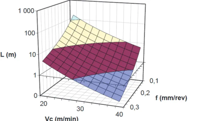
C1 245 0,457 0,739 0,028 C2 240 0,468 0,634 0,036 U1 345 0,429 0,1283 0,300 The employed tool is a HSS uncoated twist drill provided by Titex. Its outer diameter is 6 mm with flute height of 57 mm. A drill-sharpening operation is performed before any experiment to create two relief faces per cutting lip. Tool wear tests are performed within the range of cutting conditions previously determined [39]. The chosen tool wear criterion is VB = 100 µm. The tool life is expressed as a length L (m), the sum of the depth of the holes drilled until the tool wear criterion is reached.
Figure 8: Tool life for C2 steel grade
The tool wear is directly linked with the cutting speed. As can be seen in figures 7 and 8, metallurgical treatment applied to C2 steel grade improves the tool life, even at higher cutting speeds.
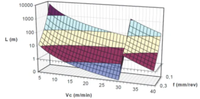
Figure 9: Tool life for U1 steel grade
Concerning the U1 steel grade (see figure 9), the wear results reveal two different domains which are representative of the two different metallurgical treatments for machinability improvement. The first one seems effective for low cutting speeds (up to 25-30 m/min), whereas the second one improves machinability at higher cutting speeds (30 m/min and higher). Despite higher mechanical properties (see table 2), U1 steel grade shows better results than C1 and C2 steel grades.
7 CONCLUSION
Recent progresses in new high strength steel grades lead to higher mechanical specifications and downsizing for automotive applications. Global cost saving requires to focus on machinability. This leads to new challenges in metallurgical treatment for machinability enhancement. The key of success depends on the steelmaker as well as the machinist since efficient machining of these improved steels is also linked to the cutting tool properties and the cutting conditions. BUL appearance depends on the tool coating or tool substrate. New experimental means and protocols are currently being applied to provide more information concerned with the thermo mechanical conditions at BUL.
8 ACKNOWLEDGEMENTS
The authors wish to acknowledge Pr. Alain D’Acunto (Arts et Métiers ParisTech Metz) as well as Olivier Pinoli (ArcelorMittal) for their support and advice.
9 REFERENCES
[1] H. Chandrasekaran, « Material development and its role in advanced machining situations », Journal of Mechanical Working Technology, vol. 17, pp. 119-136, 1988.
[2] E. Schneider, « Etude des mécanismes de formation des couches de transfert non métalliques - Applications aux aciers à très hautes caractéristiques mécaniques à usinabilité améliorée », Université Paul Verlaine Metz, Metz, 2009.
[3] F. B. Pickering, Inclusions. London: The Institution of Metallurgists, 1979.
[4] K. Iwata et K. Ueada, « The Effect of Lead on Crack Behavior of Leaded Free Machining Steel », Fourth North American Metalworking Conf., pp. 326-333, 1976. [5] G. Bernsmann, M. Bleymehl, R. Ehl, et A. Hassler, « The making of free cutting steels with additions of lead, bismuth, tellurium, selenium and tin », Stahl und Eisen, vol. 121, no 2, pp. 87-91, 2001.
[6] R. Kiessling, Non-metallic inclusions in steel Part III. London: Iron and Steel Institute, 1968.
[7] T. Gladman et F. B. Pickering, Steel and Coal, pp. 1178-1187, 1962.
[8] H. Yaguchi, « Effect of MnS inclusion size on machinabilty of low-carbon, leaded, resulfurized free-machining steel », Journal of Applied Metalworking, vol. 4, pp. 214-225, 1986.
[9] J. Fujiwara, « Cutting Mechanism of Sulfurized Free-Machining Steel », in Scanning Electron Microscopy, Osaka University, Japan, 2012, p. 353-366.
[10] E. M. Trent et P. Wright, Metal Cutting. Butterworth Heinemann, 2000.
[11] B. W. Dines, « The function of carbon and sulphur in the machining behaviour of steel », Thèse de doctorat, University of Birmingham, Birmingham, 1975.
[12] J. Bellot, « Influence des inclusions de composés du soufre, du sélénium et du tellure sur la déformabilité à chaud et les propriétés mécaniques des aciers », Thèse de doctorat, Université de Nancy 1, Nancy, 1972. [13] I. Essel, « Machinability enhancement of non-leaded free cutting steels », RWTH, Aachen, 2006.
[14] A. Melander et A. Gustavsson, « An FEM study of driving forces of short cracks at inclusions in hard steels », International Journal of Fatigue, vol. 18, no 6, pp.
389-399, 1996.
[15] G. Bittès, « Contribution à la connaissance des mécanismes fondamentaux liés à l’usinabilité des aciers de construction mécanique », Thèse de doctorat, Université de Toulon et du Var, 1993.
[16] R. Kiessling, Non-metallic inclusions in steel Part V. London: The Institute of Metals, 1989.
[17] J. Hamann, F. Le Maître, et D. Guillot, « Selective Transfer Built-up Layer Displacement in High-Speed Machining – Consequences on Tool Wear and Cutting Forces », CIRP Annals - Manufacturing Technology, vol. 43, no 1, pp. 69-72, 1994.
[18] J.-M. Brion, « Contribution à l’étude des mécanismes de formation de couches de transfert non métalliques sur un outil en coupe continue d’aciers de décolletage à inclusions contrôlées », Thèse de doctorat, Institut National Polytechnique de Lorraine, Nancy, 1993.
[19] R. M’Saoubi et H. Chandrasekaran, « Innovative methods for the investigation of tool-chip adhesion and layer formation during machining », CIRP Annals-Manufacturing Technology, vol. 54, no 1, pp. 59–62, 2005.
[20] A. Nordgren et A. Melander, « Tool wear and inclusion behaviour during turning of a calcium-treated quenched and tempered steel using coated cemented carbide tools », Wear, vol. 139, no 2, pp. 209-223, 1990.
[21] S. Ruppi, B. Hogrelius, et M. Huhtiranta, « Wear characteristics of TiC, Ti(C,N), TiN and Al2O3 coatings in
the turning of conventional and Ca-treated steels », International Journal of Refractory Metals and Hard Materials, vol. 16, no 4-6, pp. 353-368, 1998.
[22] H. S. Qi, « Formation of a transfer layer at the tool-chip interface during machining », Wear, vol. 245, no 1-2,
pp. 136-147, 2000.
[23] A. Larsson et S. Ruppi, « Structure and composition of built-up layers on coated tools during turning of Ca-treated steel », Materials Science and Engineering A, vol. 313, no 1-2, pp. 160-169, 2001.
[24] F. Schultheiss, M. Fallqvist, R. M’Saoubi, M. Olsson, et J.-E. Ståhl, « Influence of the tool surface micro topography on the tribological characteristics in metal cutting—Part II Theoretical calculations of contact conditions », Wear, vol. 298-299, pp. 23-31, 2013.
[25] Z. Pálmai, « The effect of deoxidation of steel on machinability », Wear, vol. 38, no 1, pp. 1–16, 1976.
[26] A. S. Helle, « On the interaction between inclusions in steel and the cutting tool during machining », Thèse de doctorat, Helsinki University of Technology, Helsinki, 1995.
[27] H. S. Qi et B. Mills, « On the formation mechanism of adherent layers on a cutting tool », Wear, vol. 198, no 1-2,
pp. 192-196, 1996.
[28] S. Katayama et M. Hashimura, « Effect of Tool Materials on Adhesion between Free-machining Steel and Cutting Tool », JSPE, vol. 59, pp. 1991-1996, 1993. [29] P. Helistö, A. S. Helle, et J. Pietikäinen, « Interface phenomena between oxide layers and cemented carbide tools », Wear, vol. 139, no 2, pp. 225-234, 1990.
[30] A. Nordgren et A. Melander, « Tool wear, layer formation and inclusion behavior during turning of Ca-treated quenched and tempered steel SS2541 using TiC-Al2O3-TiN coated cemented carbide tools », Swedish
Institute for Metals Research, Stockholm, IM-2228, 1987. [31] G. Brandt et M. Mikus, « The formation of protective layers when machining steel with ceramic cutting tools », Wear, vol. 118, no 1, pp. 99-112, 1987.
[32] K. Tasaka, T. Akasawa, S. Katayama, et K. Kuroiwa, « Effect of Deoxidation on Nonmetallic Inclusions in Steel and the Machinability », Tetsu-to-Hagane, vol. 57, no 13,
pp. 2076-2089, 1971.
[33] V. Grolleau, « Approche de la validation expérimentale des simulations numériques de la coupe avec prise en compte des phénomènes locaux à l’arète de l’outil », Thèse de doctorat, Ecole Centrale de Nantes, 1996.
[34] D. Robat, P. Jacquot, H. Michel, J. Bellot, et M. Gantois, « Machinability of steels containing controlled inclusions in turning with carbide or TiN-coated H.S.S. steels », presented at the 11th Int. Plansee Seminar ’85, Reutte (Austria), 1985, vol. 2, pp. 433-453.
[35] J. Bellot, « L’usinabilité des aciers de construction et les moyens permettant de l’améliorer », presented at the Progrès et évolution dans le domaine de l’usinage, de la mise en forme et de l’assemblage des métaux, Saint-Etienne (France), 1977.
[36] D. Guillot, « Contribution à l’étude de l’influence inclusionnaire sur l’usinabilité des aciers bas carbone », Thèse de doctorat, Ecole Centrale de Nantes, 1995.
[37] X. Zhang, H. Roelofs, S. Lemgen, U. Urlau, et S. V. Subramanian, « Application of thermodynamic model for inclusion control in steelmaking to improve the machinability of low carbon free cutting steels », Steel research international, vol. 75, no 5, pp. 314–321, 2004. [38] T. Kagnaya, « Contribution à l’identification des mécanismes d’usure en usinage d’un WC-6%Co par une approche tribologique et thermique », Thèse de doctorat, Mines ParisTech, 2009.
[39] A. Arzur-Bomont, M. Confente, O. Bomont, E. Schneider, et C. Lescalier, « Super High Strength Steels for automotive applications: Investigation in machinability for dry drilling operations », presented at the 10th CIRP International Workshop on Modelling of Machining Operations, Reggio di Calabria, 2007.
[40] A. Arzur-Bomont, M. Confente, E. Schneider, C. Lescalier, et O. Bomont, « Machinability in drilling - Mechanistic approach and new observer », presented at the 13th ESAFORM Conference on Material Forming, Brescia, 2010.
[41] A. Bomont, A. D’Acunto, O. Bomont, M. Cofente, et K. Inal, « Comparison of steel grades for forged and machined parts: determination of residual stresses », presented at the 7th International CIRP Workshop on Modelling of Machining Operations, Cluny (F), 2004. [42] A. Bomont, M. Confente, O. Bomont, E. Schneider, et C. Lescalier, « Influence of material structure on deep hole machinablity of super high strength steels application to crankshaft manufacturing, results and analysis », presented at the 5th International Conference on High Speed Machining, Metz (F), 2006.
[43] A. Kirsch-Racine, A. Bomont-Arzur, et M. Confente, « Calcium treatment of medium carbon steel grades for machinability enhancement: from the theory to industrial practice », Rev. Met. Paris, no 12, pp. 591-597, 2007.
![Figure 1: Schematic drawing of the behaviour of various types of inclusions during machining (after [4], [5]) A delicate balance between the deoxidisation elements used and the resulting inclusion population is required to achieve the optimum combinati](https://thumb-eu.123doks.com/thumbv2/123doknet/7338048.212144/3.892.470.830.113.378/schematic-behaviour-inclusions-machining-deoxidisation-resulting-inclusion-population.webp)
![Figure 3: Influence of calcium treatment on the inclusions in the system CaO-Al 2 O 3 -SiO 2 (after [16]) 4 BUILT-UP LAYER (BUL)](https://thumb-eu.123doks.com/thumbv2/123doknet/7338048.212144/4.892.449.808.115.399/figure-influence-calcium-treatment-inclusions-cao-built-layer.webp)
![Figure 5: Schematic presentation of the elemental distribution in the inclusion layer (after [23]) 4.4](https://thumb-eu.123doks.com/thumbv2/123doknet/7338048.212144/5.892.562.829.113.303/figure-schematic-presentation-elemental-distribution-inclusion-layer.webp)