Science Arts & Métiers (SAM)
is an open access repository that collects the work of Arts et Métiers Institute of
Technology researchers and makes it freely available over the web where possible.
This is an author-deposited version published in:
https://sam.ensam.eu
Handle ID: .
http://hdl.handle.net/10985/19686
To cite this version :
Linda AISSANI, Akram ALHUSSEIN, Corinne NOUVEAU, Lamia RADJEHI, Issam LAKDHAR,
Elia ZGHEIB - Evolution of microstructure, mechanical and tribological properties of vanadium
carbonitride coatings sputtered at different nitrogen partial pressures - Surface and Coatings
Technology - Vol. 374, p.531-540 - 2019
Any correspondence concerning this service should be sent to the repository
Administrator :
archiveouverte@ensam.eu
Evolution of microstructure, mechanical and tribological properties of
vanadium carbonitride coatings sputtered at di
fferent nitrogen partial
pressures
Linda Aissani
a,b, Akram Alhussein
c,⁎, Corinne Nouveau
d, Lamia Radjehi
a, Issam Lakdhar
c,
Elia Zgheib
caMater Science Department, ABBES Laghrour-Khenchela University, P.O. Box 1252, 40004, Algeria bMaterials and Tribology Group, Laboratory of Foundry, Annaba University BO, 12 CP 23000, Algeria
cICD–LASMIS, Université de Technologie de Troyes, CNRS, Antenne de Nogent, Pôle Technologique Sud Champagne, 26 Rue Lavoisier, 52800 Nogent, France dArts et Metiers ParisTech, Laboratoire Bourguignon des Matériaux et Procédés, Rue Porte de Paris, 71250 Cluny, France
A R T I C L E I N F O Keywords: V-C-N thinfilms Magnetron sputtering Nitrogen pressure Microstructure Wear Mechanical properties A B S T R A C T
Vanadium carbide coatings were deposited by R.F. reactive magnetron sputtering at different nitrogen partial pressures. The structures and the mechanical and tribological behaviour of these coatings were studied.
By using a combined approach of EDS and WDS, it has been shown that increasing nitrogen concentration from 0 to 27 at.% led to decrease the carbon content from 48.50 to 30.50 at.%. All coatings exhibited a dominant fcc-VC structure with additional fractions of vanadium nitrides, as determined by XRD. Nanoindentation mea-surements showed that the highest hardness of 26.1 GPa was obtained for the coating with a (N + C) / (V) ratio equal to 1.44. The transition in brittleness-ductile failure mode was noticed with increasing nitrogen content. This adhesive feature can prevent phase separation and improves the wear resistance of the coatings. Moreover, the nitrogen partial pressure showed a significant influence on the friction coefficient because of film density and residual stress effects.
1. Introduction
In the last few years, transition-metal carbides and nitrides have attracted much attention for technological purposes. They are ex-tremely hard, having high melting points, good thermal conductivity, and good corrosion and wear resistance [1–3]. Among them, vanadium nitrides are very well-known materials widely applied as hard and wear resistant protective coatings for cutting tools or other components [4]. The addition of nitrogen to vanadium enhances mechanical and tribo-logical properties, and significantly increases oxidation resistance, which is due to the formation of a dense fcc-VN phase [5]. Sarakinos reported the influence of nitrogen on the microstructure–property of reactive magnetron sputtered VeN films [6,7].
Vanadium carbides present a potential for industrial applications due to their excellent properties at high temperatures, such as good wear resistance and high hardness, attributed to the very fine grain dispersion in thin films [8]. Oliveira et al. [9] have reported the in-fluence of carbon content on the mechanical properties of vanadium carbide coatings deposited by the thermo-reactive diffusion method
[9]. Also, Wu et al. [10] studied the effect of carbon content on the mechanical properties and electronic structure of various vanadium carbides. Until now, previous studies have reported the elaboration of vanadium carbides by different methods such as: pulsed laser deposi-tion, magnetron sputtering and electron beam deposition [11–13].
Despite the vast application potential of vanadium carbide, its structural applications are limited by its brittleness, which has hindered its use in contrast to other transition-metal carbides [9,10,14]. This is especially due to the excessive amorphous carbon in the coatings that does not allow the dislocations to move and consequently a rapid fracture in the film takes place along the grain boundaries [15]. Therefore, several studies have been proposed to improve the toughness of vanadium carbide films based on their composition and micro-structure by the introduction of nitrogen atoms into the VeC film structure. According to Khyzhun et al., the introduction of nitrogen into the carbides system has been shown to be very promising for the achievement of different properties such as wear resistance, residual stresses and hardness [16]. In fact, V-C-N coatings were reported to possess different properties in comparison to coatings based on the
⁎Corresponding author.
E-mail address:akram.alhussein@utt.fr(A. Alhussein).
mixture of VeN and VeC and exhibit exceptional thermal stability at higher temperatures. The best mechanical properties may be ascribed to the formation of hard VeC bonds [9]. V–C–N thin films are produced by chemical and physical methods [9,14,17,and]. Therefore, the magne-tron sputtering technique, allowing the production offine thin films at low temperature (~300 °C) can be used for industrial deposition of films on various substrates. The elaboration of V–C–N thin films by reaction magnetron sputtering (in an argon–nitrogen atmosphere) was performed using V and C targets with different V/C atomic ratios under a nitrogen atmosphere [14] or with V target and addition of carbon and nitrogen containing reaction gases CH4and N2[15,17]. Another feature
of the reactive magnetron sputtering technique is the possibility to produce ternary thin films, which offer interesting properties for in-dustrial applications [18]. Mechanical and tribological properties of these hardfilms depend on the phases that compose the material. Va-nadium carbonitride (V-C-N) is a ternary compound that combines the excellent chemical and wear resistance of VeN [18] and VeC [9], re-spectively. For these reasons, many researchers are interested in the ternary vanadium based compounds combining nitrides and carbides to improvefilm crystallization and its performance [19,20]. Their purpose was to establish the relationship between the microstructure and the mechanical properties of vanadium carbonitride. V-C-N coatings with different carbon contents were elaborated by Grigore et al. [21]. They observed that thefilm mechanical properties were improved with ad-ditional carbon and nitrogen content in V-C-N multilayers. The hard-ness of V-C-N films reached 3380 HV0.05, being higher than that of
binary VN (2970 HV0.05) and VC (2770 HV0.05) films, due to the
for-mation of solid solution strengthening. However, limited reports are available about the effects of nitrogen on the structural, mechanical, and tribological properties of V-C-N [18–20].
Yu et al. [20] have studied the V-C-Nfilms elaborated by magnetron sputtering using vanadium and carbon targets and a mixture of reactive AreN2gas. They investigated the influence of carbon content on the
film structure. Excellent mechanical properties and wear resistance were obtained by adding carbon into the VeN matrix leading to form V-C-N solid solution. The influence of different (C + N)/V ratios on structure, mechanical properties and wear resistance of V-C-N coatings was comprehensively investigated. Previous reports on sputtered V-C-N coatings discussed either the microstructure and mechanical properties with different nitrogen content [18] or the influence of the V/(C + N)
ratio on the mechanical and tribological behaviour without under-standing the chemical bonding structure [20].
Thus, the purpose of the present study is to determine the influence of nitrogen partial pressure variation (PN2) during the sputtering
pro-cess on the structure and composition of the V-C-N coatings and relate it to mechanical properties, adhesion and tribological performance of films.
2. Experimental methods 2.1. Deposition procedure
A series of V-C-N coatings was deposited using the radio frequency
(R.F, 13.56 MHz) magnetron sputtering technique (NORDIKO 3500), equipped with two V and C targets (99.99% purity, 106 mm in dia-meter). XC100 steel (with a chemical composition of (0.95 to 1.05) wt. % C, (0.5 to 0.8) wt.% Mn, 0.25 wt.% Si, 0.05 wt.% S, 0.035 wt.% (P and S), the balance being Fe) and Si (100) were used as substrates [5]. In order to enhance the quality of substrate surfaces to obtain an average roughness Raof about 30 nm (determined by optical
profilo-metry), samples were polished with SieC carbide paper and diamond paste down to 1μm. Then, these samples were cleaned in an ultrasonic bath with acetone and ethanol (5 min per sample) and dried in air.
The substrates were placed on the centre of the substrate-holder and its distance from the targets wasfixed at 80 mm. The residual pressure was reduced to 2 × 10⁻⁵Pa. Prior to deposition, the targets and sub-strates were cleaned by Ar+ion bombardment for 5 min, applying a voltage of−700 V and −500 V, respectively.
The working pressure of 0.4 Pa was kept constant for all experi-ments. The coatings were deposited in a mixture of Ar (discharge gas) and N2(reactive gas) with different N2/Ar ratios of 0/0.4, 0.02/0.38,
0.04/0.36, 0.06/0.34, 0.08/0.32, and 0.10/0.30 (Table 1). In order to keep a constant pressure, argon and nitrogen partial pressures were adjusted and theirflow rates were controlled and regulated using MKS flow meters during the deposition process.
The V-C-Nfilms with different nitrogen contents were deposited for 120 min with constant power (bias voltage) applied to V and C targets: 550 W (−900 V) and 150 W (−300 V), respectively. The deposition temperature was maintained at 150 °C and the sample holder rotation speed was set at 30 rpm in order to obtain uniform and homogeneous coatings. The deposition parameters and chemical composition offilms are summarized inTable 1.
2.2. Characterizations: XRD, SEM, EDS, XPS, nanoindentation and tribotester
The crystallographic structure of the samples was investigated by X-ray diffraction (XRD) by means of a Siemens D5000 diffractometer. XRD analysis was carried out by using a CoKα radiation line
(λ = 1.78 Å) and applying 45 kV and 40 mA. The range of diffraction angles (2θ) was 25°–75° with a scanning speed of 2°/min. The average crystalline size of the coatings was determined with the Scherrer for-mula (Eq.(1)) [13]: = ∙ D λ β θ 0.9 cos (1)
where 0.9 is the shape factor,λ = 0.178 nm represents the X-ray wa-velength of the radiation source,β is the peak width (full width half maximum, FWHM) in radians andθ is the Bragg's angle.
The morphology analysis of surfaces and cross-sections of the V-C-N coatings was carried out by using a Jeol JSM-6400F Scanning Electron Microscope (SEM). The chemical composition of the coatings was ob-tained by combining energy and wavelength dispersive X-ray spectro-scopy (EDS, WDS).
The nature of the chemical bonds was investigated by X-ray pho-toelectron spectroscopy (Riber SIA 100 XPS, KαAl= 1468.68 eV, Table 1
Electrical power and voltage applied to the vanadium and carbon targets and the chemical composition of the VC and V-C-Nfilms deposited at 0.4 Pa during 120 min.
Coatings PN2 V target C target Chemical composition (at.%)
P(W) U(-V) P(W) U(-V) N V C O N + C/V VC 0.00 0 50.0 48.5 1.5 0.95 0.02 6.7 47.0 45.0 1.3 1.10 0.04 12.1 44.0 40.5 3.4 1.18 V-C-N 0.06 550 900 150 300 18.0 41.0 38.8 2.2 1.38 0.08 22.6 40.0 35.0 1.6 1.44 0.10 27.0 38.5 30.5 4.0 1.56
300 W). The vacuum in the spectrometer was 4 × 10⁻⁸Pa. The spec-trometer calibration was performed using binding energy level of C1s
(284.8 eV), which was absorbed on the surface of the samples. Then, the corresponding V2p, C1sand N1sspectra werefitted under a
multi-peak fitting method by using CasaXPS Software, and the ratio of Lorentzian to Gaussian was 20% [21].
The coating hardness and elastic modulus were determined by using a Nano Indenter XP, MTS Systems Corporation with continuous stiffness measurement (CSM) provided with a three-sided pyramidal diamond tip (Berkovich). Nanoindentation tests were carried out by applying a maximum load of 5 mN, 45 Hz of CSM frequency and 2 nm of oscillation amplitude. For each sample, 5 indentations were made, limiting the maximum indentation depth by up to 7% of the coating thickness in order to avoid the effect of substrate stiffness. The residual stresses were calculated from the sample-curvature radius using Stoney's formula (Eq.
(2)) [22,23]. ⎜ ⎟ = − × ⎛ ⎝ − ⎞ ⎠ σ E υ t t R R 6(1 ) 1 1 s s s f 2 0 (2)
where the subscript S refers to the substrate, Es(195 GPa) and νs
(0.29) are the Young's modulus and Poisson ratio of Si (100) substrate, respectively. tfand tsare thicknesses offilm and substrate, respectively.
R0and R are the substrate curvature radii of the uncoated Si wafer and
the coated Si wafer, which was determined by measuring the curvature of the silicon wafer before and afterfilm deposition with a three-di-mensional (3D) optical profilometer (VEECO, Wyko-NT 1100) [5].
The wear resistance of the coatings was investigated by using a TRIBO tester in dry conditions at room temperature. The ball-on-disc wear tests were performed by sliding against a 100Cr6 ball of 6 mm in diameter under a normal load of 2 N, at a constant sliding speed of 5 cm·s−1and for a sliding distance of 200 m. The wear loss was quan-tified by measuring the profile of the wear track. The wear rates (WR) of
thefilms were calculated using the following equation (Eq.(3)) after calculating the wear track area with an optical profilometer:
= ×
W Wear volum Load Sliding distance R
(3) The substrate-film adhesion was evaluated by scratch tests using a Scratch Tester Millennium 200. Measurements were carried out using a conical diamond tip with a radius of 0.2 mm. The applied load was increased from 0.01 to 40 N with a constant loading speed of 0.01 mN/ s. The stripping speed and length were 10 mm/min and 10 mm, re-spectively. The worn samples morphologies were observed by means of a SEM.
3. Results and discussion 3.1. Chemical composition
The influence of nitrogen partial pressure on the chemical compo-sition of V-C-Nfilms is presented inFig. 1andTable 1. We can see that increasing this pressure led to increase the N content gradually from 0 to 27 at.% and to decrease both V and C contents down to 38.50 at.% and 30.50 at.%, respectively. This result is in agreement with Schalk et al. [24] similarly showing a decrease in Al and Ti contents as a function of increasing nitrogen partial pressure. The partial pressures of nitrogen and argon were controlled and balanced in order to maintain the total pressure at a constant value by using MKSflowmeters during the films deposition. Increasing nitrogen partial pressure caused the poisoning of targets and the reduction of ionization leading conse-quently to a lower amount of vanadium and carbon during sputtering. This confirms the gradual decrease of the V and C deposition rates, with increasing nitrogen partial pressure. Consistently, by increasing the pressure of nitrogen from 0 to 0.10 Pa, the (N + C)/V ratio increased from 0.95 to 1.56. All films contained a small amount of oxygen
(1.5–3 at.%), which might be induced by residual oxygen in the de-position chamber and contamination of the targets.
3.2. Microstructure
The evolution of the microstructure of V-C-N coatings with in-creasing PN2is shown inFig. 2. At low diffraction angles (between 26°
and 33°) small crystallographic planes emerge and indicate the pre-sence of V5O9phase (JCPDS card, No. 18-1450) for all coatings, which
the oxygen mainly induced in thefilms and partly replaced the nitrogen and carbon. The diffraction patterns of films sputtered at 0 and 0.02 Pa show fcc-VC phase (JCPDS card, No. 07-0257) with strong diffraction from (111), (200) and (101) crystallographic planes at (43.9°), (47.4°) and (49.7°), respectively. The orthorhombic V2C phase (JCPDS card,
No. 71-1258) was also detected on (202) and (131) crystallographic
0
10
20
30
40
50
60
0.00
0.02
0.04
0.06
0.08
0.10
1.56
1.38
1.44
1.18
1.10
0.95
(N + C)/V ratio
%.
t
a
,
n
oi
ti
s
o
p
m
o
c
l
at
n
e
m
el
E
P N
2(Pa)
N
C
V
0
Fig. 1. Variation of chemical composition for V-C-N coatings as a function of nitrogen partial pressure.
Fig. 2. X-ray diffraction patterns for V-C-N coatings sputtered at different ni-trogen partial pressures.
planes corresponding to diffraction 2θ angles of 54.9° and 56°, respec-tively. The films sputtered with varying pressure between 0.04 and 0.08 Pa presented a significant reduction in V2C and VC phases. The
V2C crystallographic plane is no longer visible and the intensity of (101)
VC crystallographic plane becomes very low. The gradually weakened peaks indicate the poor crystallization of vanadium carbides. However, the XRD diffraction patterns show a high peak situated at 52.4°, re-presenting a tetragonal (400) VN.81phase (JCPDS card, No. 71-1139).
Also, the crystallographic planes at 54.78° assigning to the (201) re-flection of V2N was detected (JCPDS card, No. 71-0618). This is due to
vanadium significantly exhibiting a more negative enthalpy when it combines with nitrogen.
The high quantity of nitrogen in film corresponding to a partial pressure of 0.10 Pa led to significantly change the film structure. From
Fig. 2, we can see the appearance of several VN0.81crystallographic
planes and the hexagonal V2N phase related to the (101), (201) and
(210) crystallographic planes located at 33.9°, 54.9° and 68.2°, re-spectively. It should be noted that all films deposited with different (N + C)/V ratios varied between 1.10 and 1.56 presented a dominant tetragonal VN.81phase similar to the tetragonal V5N phase reported in
reference [20].
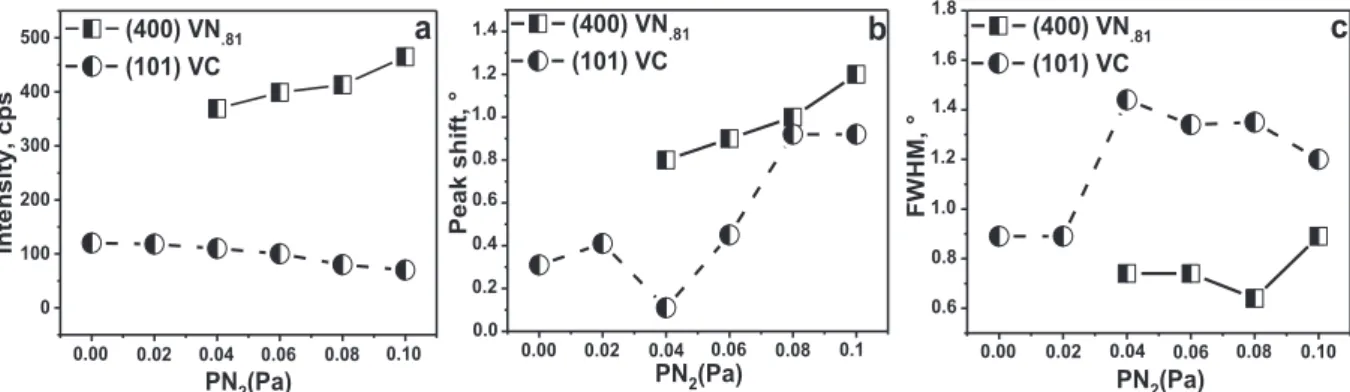
Fig. 3presents the variation of intensity, peak shift and FWHM as a function of nitrogen partial pressure for V-C-N coatings. These results were obtained for both (400) VN.81and (101) VC phases.
Generally, increasing pressure led to increase all these parameters for both phases except the intensity of (101) VC phase (Fig. 3). These changes in (101) VC and (400) VN.81peak intensities, FWHM and
po-sitions suggest that the distortion of the VC lattice occurs progressively as the nitrogen content in the coating increases. Addition of nitrogen led to a progressive replacement of the vanadium carbides by orthor-hombic vanadium nitride resulting in a severe decrease in intensity accompanied by an increase in FWHM of the (101) VC. This is due to the poor crystallization of vanadium carbides and the moderate ex-istence of carbon in the coatings in its amorphous state [25]. This is in good agreement with N. Schalk [24], who reported the decreasing of stress-free lattice parameters with increasing nitrogen content in the sputtered titanium aluminium nitride coatings. We can also relate these changes in coating microstructure to the compressive residual stress introduced in coatings, during sputtering, by the complex nature of the diffusion of vanadium, nitrogen and carbon atoms [23].
In order to determine the binding state, simultaneous XPS was carried out on the coatings. FromFig. 4, one can see that the coating surface mainly consists of V, C, and N. At 0.01 Pa,the high-resolution
V2p spectrum shows peaks at the binding energies of the V2p(3/2,1/2)
(513.47 and 515.28 eV, FWHM 1.07 eV). The aforementioned peaks can be explained with three binding energies (Fig. 4a): peaks of V2p3/2
(513.52 eV, FWHM 1.02 eV) and V2p1/2(515.13 eV, FWHM 2.22 eV)
which are assigned to the VeC bond of the VC component [26,27], while the third peak of V2p3/2 (513.12 eV, FWHM 1.16.4 eV) is
as-signed to V2C [27]. Moreover, the C1s peak at the binding energy of
283.4 eV also demonstrates the presence of a CeV bond of VC (Fig. 4c) [27,28], which were supported by the XRD data. The results are similar to those reported in the literature for VC phase [29]. For the N1 s XPS spectra (397.44 eV, FWHM 1.56 eV) (Fig. 4e), the main peak of N1 s corresponds to V2N (397.40 eV, FWHM 1.54 eV) [5] and the minor
peak corresponds to VNx(297.80 eV, FWHM 2.82 eV) [30]. These
re-sults mean that vanadium carbide and nitride coexist in the coating as shown from the XRD analysis (Fig. 2).
At 0.06 Pa, we notice a significant decrease in the C1s spectra in-tensity and changes in the V and N1 s spectra. A positive shift from 513.47 up to 514.21 eV for the peaks of V2p is observed. The V2p(3/2, 1/2)(514.21 and 521.61 eV, FWHM 2.25 eV) spectra can befitted into
four peaks, located at about (513.81 eV, FWHM 1.39 eV), (516.7 eV, FWHM 2.89 eV) (517.31 eV, FWHM 2.36 eV) and (522.079 eV, FWHM 2.46 eV) (Fig. 4b), corresponding to VN.81, V2N, VC and VOx[5,31].
The C1s spectrum is located at a binding energy of 282.86 eV (Fig. 4d). Through Gaussian fitting analysis, the peaks at (282.84 eV, FWHM 1.20 eV) and (283.67 eV, FWHM 3.07 eV) correspond to VeC and CeN bonds [26,32]. This indicates that the CeN binding is weakly formed in the V-C-N coatings after incorporation of nitrogen atoms and confirms the coexistence of vanadium nitride and carbide phases in the V-C-N system at high nitrogen content. However, the vanadium carbonitrides do not appear in the XRD diffraction patterns (Fig. 2), showing that the content of vanadium carbonitride is very low. The peak size of N1s between 397.36 and 398.78 eV becomes large and asymmetric (Fig. 4f). The main peak of N1s spectra corresponds to VN.81(397.25, FWHM
2.42 eV) and the minor peak corresponds to V2N (398.56 eV, FWHM
2.42 eV) [5,30]. However, the third peak corresponds to NeC bond (398.39 eV, FWHM 1.60 eV) [32]. The XRD and XPS analysis results reveal that V-C-N coatings are an interstitial (VeC, VeN) mixture, which exhibits a crystalline structure. However, the VeC binding in-tensity decreases gradually while VeN binding increases. This suggests that VeN and VeC bonds coexist in the coatings and the content of VN.81 increases while the VC content decreases with increasing N
content. 3.3. Morphology
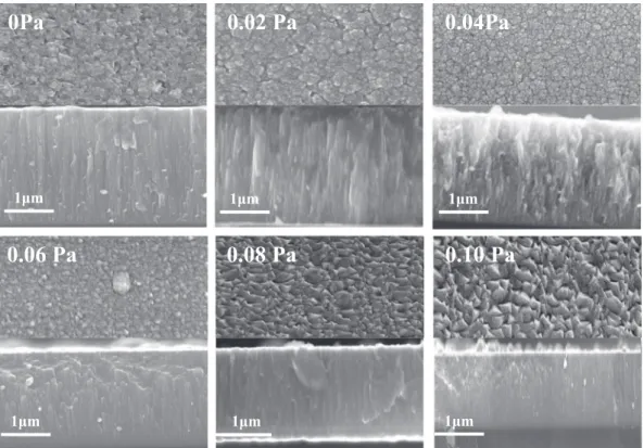
SEM images showing the cross section and surface morphology of V-C-N coatings are represented inFig. 5.Fig. 6presents the variation of film thickness, growth rate and crystallite size of films deposited at different nitrogen partial pressures. One can notice that the surface of coatings sputtered at low pressure varied between 0 and 0.04 Pa, re-vealing a porous surface withfine grains of 14 and 12 nm respectively (Fig. 5). Thefilms deposited at PN2= 0.06 Pa present uniform andfine
grains. Increasing the pressure led to decrease the growth rate of V-C-N films (Fig. 6). In fact, the addition of nitrogen led to modify the growth mode offilms with the presence of amorphous carbon. By increasing the pressure up to 0.08 Pa, significant changes in coating morphology were observed such as pyramidal like sharp grains (26 mm in size,Figs. 5 and
0 100 200 300 400 500 0.10 0.08 0.06 0.04 0.02
a
s p c , yt i s n et nI PN2(Pa) (400) VN.81 (101) VC 0.00 1.8 1.6 1.4 1.2 1.0 0.8 0.6 0.10 0.08 0.06 0.04 0.02 0.00c
PN2(Pa) (400) VN.81 (101) VC ° , M H W F 1.4 1.2 1.0 0.8 0.6 0.4 0.2 0.0 0.1 0.08 0.06 0.04 0.02 0.00b
PN2(Pa) (400) VN.81 (101) VC ° ,t fi h s k a e P6). The pyramidal grain size increased gradually with increasing pres-sure from 0.08 to 0.10 Pa (Figs. 5 and 6). In our previous study [29], we reported a similar evolution of the morphology of VeN coatings de-posited by the same procedure, which is a result of the mutual inter-ference of the intermediate VN and V2N phases.
The grain size of V-C-Nfilms sputtered at PN2> 0.06 Pa clearly
increased simultaneously with decreasing thefilm thickness. The grain coalescence, performed with increasing the N content infilms, is due to the reduction of ion bombardment energy during the reactive sput-tering of V, C and N elements and the re-nucleate on the VeN com-pounds throughfilm deposition [3].
Cross-sectional SEM images (Fig. 5) show a columnar morphology for all coatings with different column widths. A similar morphology was reported by Bondarev et al. [18].
We noticed that a superficial thin oxide layer was subsequently formed, the thickness of which depends on the applied nitrogen partial pressure. Its maximum value (≈0.11 μm) was measured for the film deposited at 0.04 Pa, which contained about 3.4 at.% of oxygen. The formation of this oxide layer is due to the reduction in dense structure caused by the low kinetic energy of incidence ions, which increased nucleation of oxides during film growth [33]. From Fig. 6, we can clearly see that growth rate andfilm thickness, evaluated by SEM, de-crease from 0.0022μm/min, 2.41 μm (at 0 Pa) to 0.0013 μm/min, 1.60μm (at 0.10 Pa), respectively. This behaviour can also be explained by the pollution of the target and the re-nucleation of the vanadium nitrides throughfilm deposition. It may also be slightly affected by the low compact solid solution, which decreases by increasing nitrogen
content as compared to the VeC coatings [34,35].
3.4. Mechanical properties
To investigate the mechanical behaviour of the V-C-Nfilms sput-tered at different nitrogen partial pressures, nanoindentation mea-surements were performed.Fig. 7(a) illustrates the typical load-dis-placement curves obtained from these tests. It can be shown that these curves are superimposed at low loads < 100 mN, signifying that elastic deformation is dominant at this stage for all coatings [29].
The maximum applied load was about 700 mN, which allowed achieving maximum indentation depths (Fig. 7a, b). With a limit of 7% of totalfilm thickness, it clearly shows a stiffer plastic response, as is demonstrated by the lower indentation depth and greater loading cur-vature.
This response results in a smaller depth with an equivalent max-imum load than compared with load-displacement curves without taking a limit of 10% of totalfilm thickness. Suggesting the V-C-N films are more resistant to plastic deformation than a steel substrate; this qualitative analysis confirmed the inactive effect of the substrate on the hardness values (Fig. 7a, b). It can also easily be seen that the load-displacement curves stabilized as thefilm thickness increased, which can be explained by strain gradient effect or the Hall-Petch effect [36]. Also, the higher the nitrogen pressure, the higher the penetration depth is. This indicates that the plastic deformation of vanadium nitrides is lower than that of vanadium carbides.
Mechanical properties of coatings sputtered at different PN2 are
512 514 516 518 100000 120000 140000 160000 180000 200000 ). u. a( S P C Binding Energy (e V) 515.17 eV 513.47 eV V2p1/2 V2p3/2 513.13 eV V-C V-C V-C
P
N 2=0.01 Pa
a
)V2p
512 516 520 524 0 10000 20000 30000 40000 V2p1/2 V2p3/2 513.20 eV 517.06 eV 514.60 eV 513.20 eV ). u. a( S P C Binding Energy (e V) V-C V-N V-C V-Ob
)V2p
P
N2=0.06 Pa
280 282 284 0 2000 4000 6000 8000 10000 12000 ). u. a( S P C Binding Energy (e V) 283.71 eV 283.23 eV V-C 282.71 eV V-Cd
) C1s
P
N 2=0.06 Pa
280 282 284 0 2000 4000 6000 8000 10000 12000 14000 283.67 eV 282.85 eV V-C V-C 282.85 eV ). u. a( S P C Binding Energy (e V)P
N 2=0.01 Pa
c
) C1s
394 396 398 400 0 1000 2000 3000 4000 5000 397.80 eV 397.40 eV 397.44 eVP
N 2=0.01 Pa
V-N V-Ne
) N1s
Binding Energy (e V) ). u. a( S P C 394 396 398 400 0 2000 4000 6000 8000 10000 12000 397.38 eV 398.89 eV 398.51 eV 397.27 eV V-N V-N V-N Binding Energy (e V) ). u. a( S P Cf
)N1s
P
N 2=0.06 Pa
summarized in Fig. 7(c) andTable 2. The coating hardness (H) and elastic modulus (E) increased with an increase of PN2up to 0.06 Pa and
then, beyond this value, they decreased gradually. The H and E values were measured with considering 7% of totalfilm thickness. For a pure VC coating, the average hardness value was 15 GPa. Wefind that the V-C-Nfilms have a significant increase in hardness and elastic modulus, from (H = 17 ± 2 GPa, E = 220 ± 10 GPa) at PN2= 0.02 Pa to
(H = 26.1 ± 1.0 GPa, E = 268 ± 10 GPa) at PN2= 0.06 Pa (Fig. 7c).
This can be explained by the increasing density and sub-stoichiometric films with a mixture of vanadium carbide and nitride phases. According to XPS analysis, the peak shift of V2p binding energy suggests that the bonding character changed from VeC to harder VeN bonds due to the N insertion through V atoms [23,37].
FromFig. 2, the XRD diffraction pattern of the film sputtered at 0.06 Pa shows a major (400) VN.81peak indicating the effect of solid
solution strengthening of the V-C-N coating by nitrogen atoms in-corporation and grain refinement [2,32]. At a higher PN2, the structure
was polycrystalline and the (N + C)/V ratio further increased and reached 1.56 at PN2= 0.10 Pa. This is considerably higher than that of
VN.81and VC phases, typically exhibiting a decrease in the hardness
and elastic modulus, which is consistent with several works in the lit-erature [19,38]. It seems that the low hardness of coatings deposited at PN2= 0.10 Pa is due to the large grain size (37 nm,Fig. 5) and the low
film thickness according to the Hall-Petch relation [19]. Furthermore, the V-C-N coating suffers from significant oxygen contamination which typically reacts with vanadium, forming oxides and affects harmfully the mechanical properties [5].
The elastoplastic behaviour of coatings can be investigated by H/E and H3/E2ratios. Both ratios are related to the toughness of the
coat-ings [31] varied similarly. The highest elastic and plastic strain ratios of 0.097 and 0.224 GPa respectively, were obtained for the coating de-posited at 0.06 Pa. This is mostly a consequence of the low elastic modulus value, as compared to those of other hardfilms [25–33]. The addition of nitrogen led to significantly change the chemical composi-tion, in particular the (N + C)/V ratio (Fig. 1), and consequently the microstructure of the coatings (Figs. 2 and 5). The H/E and H3/E2ratios
of all V-C-Nfilms, except the film deposited at 0.1 Pa, are higher than that of a pure VC coating [20].
The values of residual stresses calculated from the sample-curvature radius using Stoney's formula are shown in Table 2. We found that compressive residual stresses produced during sputtering in pure VC were−2.2 GPa. By increasing the nitrogen pressure, the lowest value of this stress was measured in thefilm sputtered at 0.06 Pa (0.4 GPa). The drop in residual stress with the addition of nitrogen can be explained by the changes infilm growth due to the incorporation of nitrogen in the vanadium lattice. We found that mechanical properties of V-C-N coat-ings deposited at 0.06 Pa were close to those previously reported for V-C-N coatings with N + V = 83.01 at.%, and C = 16.89 at.% [20]. Moreover, the drop in the mechanical properties can be explained by the relaxation of residual stress and the formation of V2N phase at high
nitrogen content, which is less dense as compared to the VN.81phase
0.06 Pa
0.08 Pa
0.10 Pa
1μm
1μm
1μm
0Pa
0.02 Pa
0.04Pa
1μm
1μm
1μm
Fig. 5. SEM images of surface and cross-sections for V-C-N coatings sputtered at different nitrogen partial pressures.
2.8
2.6
2.4
2.2
2.0
1.8
1.6
(400) VN.81 (101) VC (101) VC (400) VN.81 (400) VN.81 (400) VN.81Growth rate( m/min) Thickness( m) Crystallite size (nm)
PN
2(Pa)
et ar ht w or G( 0 1* ni m/ m -3 )s s e n k ci h T ,( m ) 5 10 15 20 25 30 35 401.4
0.10
0.08
0.06
0.04
0.02
0.00
) m n( e zi s et il l at s yr C µ µ µ µFig. 6. Growth rate, film thickness and crystallite size for V-C-N coatings sputtered at different nitrogen partial pressures.
[5].
3.5. Tribological properties 3.5.1. Friction
Fig. 8shows the friction coefficient curves of the V-C-N coatings
sputtered at different nitrogen partial pressures. The friction coeffi-cients of all V-C-N coatings are characterized by two different parts. For V-C-N, the friction coefficient (CoF) is not constant during the test. An initial running-in period, during which the CoF rises rapidly can be observed, which represents a transition pattern of friction for rough surfaces. This is followed by a steady-state region which varies from test to test, from a minimum of 3 m of the total sliding distance [39].
Surface roughness (RMS) and friction coefficient (CoF) of V-C-N coatings deposited at different nitrogen pressures are presented in
Table 3. The RMS value of VCfilm was close to that of a V-C-N coating deposited at 0.02 Pa. FromTable 3, we can note that increasing the nitrogen pressure led to significantly decrease the coating roughness, which may be due to the competitive growth between vanadium car-bides and nitrides [23]. The low surface roughness can affect friction and wear performance during the sliding test. The CoF average of the V-C-N coating, measured against a 100Cr6 ball, was 0.42 at 0.06 Pa
0 100 200 300 400 500 600 700 800 2100 1800 1500 1200 900 600 300
b
N
m
,
d
a
o
L
Indentation depth, nm
0 Pa 0.02 Pa 0.04 Pa 0.06 Pa 0.08 Pa 0.1 Pa 0 100 200 300 400 500 600 700 800 180 160 120 80 40 0a
N
m
,
d
a
o
L
Indentation depth, nm
0 Pa 0.02 Pa 0.04 Pa 0.06 Pa 0.08 Pa 0.1 Pa 300 250 200 25 20 15 10 0.1 0.08 0.06 0.04 0.02 PN2 (Pa) 0.00c
a P G , s ul u d o m ci t s al E a P G , s s e n dr a HH(GPa)
E(GPa)
Fig. 7. Load-displacement curves as a function of the indenter penetration depth: a) maximum penetration limited to 7% of the totalfilm thickness, b) without limited penetration and c) hardness and elastic modulus for V-C-N coatings sputtered at different nitrogen partial pressures.
Table 2
Mechanical properties of V-C-N coatings. PN2, Pa 7% of totalfilm
thickness, nm
H, GPa E, GPa H/E H3/E2,
GPa R. stresses, (GPa) 0 168 15 ± 2 210 ± 10 0.071 0.077 2.2 0.02 147 17 ± 2 220 ± 10 0.077 0.102 1.9 0.04 140 18 ± 1 234 ± 10 0.077 0.107 1.6 0.06 133 26 ± 1 268 ± 10 0.097 0.245 0.4 0.08 114 22 ± 1 263 ± 10 0.083 0.154 0.5 0.1 112 14 ± 2 220 ± 10 0.063 0.057 0.8
0
2
4
6
8
10
12
14
0 Pa 0.02 Pa 0.04 Pa 0.06 Pa 0.08 Pa 0.1 Pa0.26
0.32
0.38
0.56
0.50
0.44
0.62
,t
n
ei
ci
ff
e
o
c
n
oi
t
ci
r
F
Sliding distance, m
µFig. 8. Friction coefficient vs. the sliding distance for the V-C-N coatings sputtered at different nitrogen partial pressures.
Table 3
Roughness and tribological properties of V-C-N coatings. PN2, Pa Roughness Tribological properties
RMS, nm CoF WR(×10−7), mm3/Nm 0 41 0.62 11.30 0.02 37 0.58 8.21 0.04 26 0.56 4.25 0.06 8 0.44 2.22 0.08 10 0.47 2.66 0.10 11 0.56 4.20
(Fig. 8) close to the values reported by Ge et al. [40].
The CoF values for the V-C-N coatings deposited at different PN2
varying from 0.04 to 0.08 Pa were similar to those previously reported by Bondarev and Yu [18,20] indicating a positive influence of nitrogen
addition. The V-C-N coating deposited at 0.10 Pa unexpectedly de-monstrated a high CoF value which can be explained by the decrease in the VN.81phase with a significant (N + C)/V ratio = 1.65. In fact,
ni-trogen addition causes surface softness of V-C-N films (H = 14 GPa) leading to increase the contact area and consequently the friction force during sliding test [39]. Thus, these results are in partial accordance with a previous study showing a decrease in the CoF [18]. According to our previous study [8], the decrease in the CoF is also attributed to the contamination of the V-C-N coating by oxygen and the formation of vanadium oxides. These oxides act as a lubricant between the film surface and the ball resulting in a low friction coefficient. The decrease in the surface roughness of V-C-N coatings having a higher (N + C)/V ratio indicates the negative influence of a low carbon content in the coatings [18].
3.5.2. Wear
Micrographs and cross-sectional wear track depth profiles of the V-C-N samples are presented inFig. 9. The wear rate values are presented inTable 3. For thefilms deposited at a low nitrogen pressure ≤ 0.04 Pa, the spallation failure mode is observed and the total delamination of the V-C-Nfilms is due to the low resistance to plastic deformation (Fig. 7a) [23]. The V-C-N coatings deposited at 0.06 and 0.08 Pa confirm an especially good wear resistance; their wear rates are in the range of 2.66 × 10⁻⁷mm3/Nm. A little abrasion wear is observed in the middle of wear tracks parallel to the sliding direction, which is attributed to its low surface roughness and high hardness value [18,23]. The SEM images of coatings sputtered at 0.04 and 0.10 Pa show a significant amount of wear debris accumulated on the wear track and the wear rate for both films is 4.20 × 10⁻⁷mm3/Nm. This result indicates that
abrasion is due to the low resistance offilms to plastic strain, which is
expected in ductile films [18,41]. 3.5.3. Adhesion
Scratch tests were carried out on V-C-N coatings by applying dif-ferent loads of 5, 20 and 40 N. The scratch tracks were investigated to evaluate the influence of nitrogen partial pressure on the film adhesion and to reveal the damage nature between the coating and the XC100 substrate. The SEM images of scratch tracks are presented inFig. 10. For all samples; applying a low charge of 5 N did not cause any failure in the scratch track. A further increase in the applied load to 10 N led to initiate and propagate cracks through coatings. Wear track morphology of V-C-N deposited at 0.06 Pa was relatively smooth. We did not ob-serve spallation or delamination of the coating. However, some chip-ping of layers at the edges of the scratch can be observed. The wear tracks of V-C-N coatings sputtered at 0 and 0.10 Pa have a very rough surface. The track becomes broader and the conformal cracks along the scratch edge are visible. This is a typical brittle-ductile behaviour in V-C-N coatings [29]. The cohesive failure of the V-C-N coatings is a re-sponse to the internal stress developed within the coatings during the test where cracking occurs in high stress areas [22,42].
By increasing the applied load up to 40 N, it can be seen that the wear resistance of the very hard V-C-N coatings is even higher than that of the VeC coating. This adhesive feature is confirmed by the char-acteristics of the wear track. For the V-C-N coating deposited at 0.06 Pa, the wear track reveals few cracks. According to Sun et al. [42], the transition-metal carbonitride coatings become harder when the energy of crack propagation decreases with the reduction of the carbon con-tent, which is in agreement with our results. However, all coatings present deterioration, an obvious delamination and cracks on track edges of the scratch. The plastic deformation along the tracks is caused by tensile stress behind the sliding stylus [43].
50 100 150 200 0.25 0.20 0.15 0.10 0.05 -0.00 -0.05 -0.10 -0.15 -0.20 -0.25 m µ , ht p e d k c ar T
Lateral distance (µm)
%(PN2=0 Pa % (PN2=0.02 Pa) %(PN2=0.04 Pa % (PN2=0.06 Pa) %(PN2=0.08 Pa % (PN2=0.1 Pa)0 Pa
0.02 Pa
0.04 Pa
0.06 Pa
0.08 Pa
0.10 Pa
100μm
100μm
100μm
100μm
100μm
100μm
4. Conclusion
In this paper, the effects of nitrogen partial pressure on the struc-ture, morphology, mechanical and tribological properties of the Vanadium carbonitride magnetron sputtered coatings were in-vestigated.
✓ V-C-N coatings sputtered at low pressure ≤ 0.04 Pa consisted of solid solution of fcc-VC and hcp-V2C. Increasing the nitrogen partial
pressure led to change the microstructure of thefilms to hcp-V2N
and t-VN.81 phases. This is due to the incorporation of nitrogen
through the vanadium lattice. However, the VC carbide appeared in low amounts at 0.10 Pa.
✓ It was demonstrated that the porous morphology changes to a dense one with a pyramid like peak when nitrogen atoms are incorporated into the vanadium lattice.
✓ The hardest V-C-N film was sputtered at 0.06 Pa of nitrogen partial pressure with the formation of a vanadium carbide and nitride mixture. Its value of 26.1 GPa was obtained with (N + C) / V = 1.44. Thisfilm showed an excellent strength to elastoplastic deformation. The mechanical parameters of V-C-Nfilms gradually decreased with grain coalescence.
✓ The V-C-N film sputtered at 0.06 Pa revealed the lowest friction coefficient (0.42) and the best wear performance. However, in-creasing the nitrogen partial pressure to > 0.08 Pa led to a decrease in thefilm resistance to plastic strain and the total delamination of all the V-C-N coatings.
Acknowledgements
The authors would like to thank the support of PVD Coatings Project for the equipment supplied by the La.Bo.Ma.P at Arts et Metiers ParisTech of Cluny, which was used in this study. We would like to thank Pr. IMHOFF for the XPS and SEM analysis of the test samples.
References
[1] M.T. Hosseinnejad, M. Ghoranneviss, G.R. Etaati, M. Shirazi, Z. Ghorannevis,
Deposition of tungsten nitride thinfilms by plasma focus device at different axial
and angular positions, Appl. Surf. Sci. 257 (2011) 7653–7658.
[2] H. Zhao, Z. Ni, F. Ye, Structure and mechanical properties of reactive sputtered
WCNfilms, Surf. Eng. 32 (4) (2016) 307–313.
[3] C.P. West, I. Harrison, E.J. Cussen, D.H. Gregory, Facile synthesis of bimetallic
carbonitrides, V1−xTix(C, N), by microwave carbothermal reduction–ammonolysis/
carburisation (MW-CRAC) methods, J. Eur. Ceram. Soc. 29 (2009) 2355–2361.
[4] N.S. Gajbhiye, R.S. Ningthoujam, Low temperature synthesis, crystal structure and
thermal stability studies of nanocrystalline VN particles, Mater. Res. Bull. 41 (2006)
1612–1621.
[5] L. Aissani, C. Nouveau, M.J. Walock, H. Djebaili, A. Djelloul, Influence of vanadium
on structure, mechanical and tribological properties of CrN coatings, Surf. Eng. 31
(10) (2015) 779–788.
[6] Y. Qiu, S. Zhang, B. Li, J.-W. Lee, D. Zhao, Influence of nitrogen partial pressure and
substrate bias on the mechanical properties of VN coatings, Procedia Eng. 36 (2012)
217–225.
[7] K. Sarakinos, J. Alami, D. Severin, P.M. Karimi, M. Wutti, The effect of the
back-scattered energetic atoms on the stress generation and the surface morphology of
reactively sputtered vanadium nitridefilms, Thin Solid Films 516 (14) (2008)
4568–4573.
[8] C. Aguzzoli, C.A. Figueroa, F.S. Souza, A. Spinelli, I.J.R. Baumvol, Corrosion and
nanomechanical properties of vanadium carbide thinfilm coatings of tool steel,
Surf. Coat. Technol. 206 (2012) 2725–2731.
[9] C.K.N. Oliveira, C.L. Benassi, L.C. Casteletti, Evaluation of hard coatings obtained
on AISID2 steel by thermo-reactive deposition treatment, Surf. Coat. Technol. 201
(2006) 1880–1885.
[10] L. Wu, T. Yao, Y. Wang, J. Zhang, F. Xiao, B. Liao, Understanding the mechanical
properties of vanadium carbides: nano-indentation measurement and
first-princi-ples calculations, J. Alloys Compd. 548 (2013) 60–64.
[11] R. Teghil, A.D. Bonis, A. Galasso, P. Villani, A. Santagata, D. Ferro, S.M. Barinov,
Nanostructured thinfilms obtained by ultra-short pulse laser deposition of
vana-dium carbide, Appl. Surf. Sci. 255 (2009) 5220–5223.
[12] X. Zhang, B. Wang, Z. Zhan, F. Huang, Microstructure, chemical states, and
me-chanical properties of V–C–Co coatings prepared by non-reactive magnetron
sput-tering, Thin Solid Films 540 (2013) 135–141.
[13] E. Portolan, C.L.G. Amorim, G.V. Soares, C. Aguzzoli, C.A. Perottoni,
I.J.R. Baumvol, C.A. Figueroa, Carbon occupancy of interstitial sites in vanadium
carbidefilms deposited by direct current reactive magnetron sputtering, Thin Solid
Films 517 (24) (2009) 6493–6496.
[14] U. Jansson, E. Lewin, Sputter deposition of transition-metal carbidefilms — a
cri-tical review from a chemical perspective, Thin Solid Films 536 (2013) 1–24.
[15] M.E. Launey, R.O. Ritchie, On the fracture toughness of advanced materials, Adv.
Mater. 21 (2009) 2103–2110.
[16] O.Y. Khyzhun, V.A. Kolyagin, Electronic structure of cubic and rhombo-hedral
tantalum carbonitrides studied by XPS, XES, and XAS methods, J. Electron.
Spectrosc. Relat. Phenom. 137–140 (2004) 463–467.
[17] C. Mitterer, N. Fateh, F. Munnik, Microstructure–property relations of reactively
magnetron sputtered VCxNyfilms, Surf. Coat. Technol. 205 (13–14) (2011)
3805–3809.
[18] A.V. Bondarev, M. Golizadeh, N.V. Shvyndina, I.V. Shchetinin, D.V. Shtansky,
Microstructure, mechanical, and tribological properties of Ag-free and Ag doped
VCN coatings, Surf. Coat. Technol. 331 (2017) 77–84.
[19] C.L. Yeh, Y.D. Chen, Combustion synthesis of vanadium carbonitride from V-C
powder compacts under nitrogen pressure, Ceram. Int. 33 (2007) 365–371.
[20] L. Yu, Y. Li, H. Ju, J. Xu, Microstructure, mechanical and tribological properties of
magnetron sputtered VCNfilms, Surf. Eng. 33 (2017) 919–924.
[21] E. Grigore, C. Ruset, C. Luculescu, The structure and properties of VN-VCN-VC
coatings deposited by a high energy ion assisted magnetron sputtering method,
Surf. Coat. Technol. 205 (2) (2011) S29–S32.
[22] E. Grigore, C. Ruset, X. Li, H. Dong, The influence of carbon content on the
char-acteristics of V–C–N coatings deposited by combined magnetron sputtering and ion
implantation (CMSII), Surf. Coat. Technol. 204 (2010) 2006–2009.
[23] L. Aissani, M. Fellah, C. Nouveau, M.A. Samad, A. Montagne, A. Iost, Structural and
mechanical properties of Cr–Zr–N coatings with different Zr content, Surf. Eng. 34
(2017) 1–9.
[24] N. Schalk, J. Simonet Fotso, D. Holec, G. Jakopic, A. Fian, V. Terziyska, R. Daniel,
C. Mitterer, Influence of varying nitrogen partial pressures on microstructure, me-chanical and optical properties of sputtered TiAlON coatings, Acta Mater. 119
(2016) 26–34.
[25] X. Wu, G. Li, Y. Chen, G. Li, Microstructure and mechanical properties of vanadium
carbide coatings synthesized by reactive magnetron sputtering, Int. J. Refract. Met.
Hard Mater. 27 (2009) 611–614.
[26] F. Liu, Y. Yao, H. Zhang, Y. Kang, G. Yin, Z. Huang, X. Liao, X. Liang, Synthesis and
characterization of vanadium carbide nanoparticles by thermal refluxing-derived
precursors, J. Mater. Sci. 46 (2011) 3693–3697.
[27] G. Greczynski, D. Primetzhofer, L. Hultman, Reference binding energies of
transi-tion metal carbides by core-level X-ray photoelectron spectroscopy free from Ar+
etching artefacts, Appl. Surf. Sci. 436 (2018) 102–110.
[28] R. Teghil, A. De Bonis, A. Galasso, P. Villani, A. Santagata, D. Ferro, S.M. Barinov,
Nanostructured thinfilms obtained by ultra-short pulse laser deposition of
vana-dium carbide, Appl. Surf. Sci. 255 (2009) 5220–5223.
[29] X. Cai, L. Zhong, Y. Xu, Z. Lu, J. Li, J. Zhu, Y. Ding, H. Yan, Microstructural
characterization of a V2C and V8C7ceramic-reinforced Fe substrate surface
com-pound layer by EBSD and TEM, J. Alloys Compd. 747 (2018) 8–20.
[30] J.H. Ouyang, S. Sasaki, The friction and wear characteristics of cathodic arc
ion-plated (V, Ti) N coatings in sliding against alumina ball, Wear 257 (7–8) (2004)
708–720.
[31] J.-G. Choi, The surface properties of vanadium compounds by X-ray photoelectron
spectroscopy, Appl. Surf. Sci. 148 (1999) 64–72.
[32] L. Aissani, M. Fellah, L. Radjehi, C. Nouveau, A. Montagne, A. Alhussein, Effect of
annealing treatment on the microstructure, mechanical and tribological properties
of chromium carbonitride coatings, Surf. Coat. Technol. 359 (2019) 403–413.
[33] L. Aissani, C. Nouveau, M.J. Walock, H. Djebaili, A. Djelloul, Influence of vanadium
on structure, mechanical and tribological properties of CrN coatings, Surf. Eng. 31
(10) (2015) 779–788.
[34] C.I. Enriquez-Flores, E. Cruz-Valeriano, A. Gutierrez-Peralta, J.J.
Gervacio-Arciniega, E. Ramírez-Álvarez, E. Leon-Sarabia, J. Moreno-Palmerin, Relation be-tween work function, microstructural and mechanical properties of TiN-films, Surf.
Eng. 34 (2018) 660–666.
[35] P. Stoyanov, J. Schneider, M. Rinke, S. Ulrich, E. Nold, M. Dienwiebel, M. Stüber,
Microstructure, mechanical properties and friction behavior of
magnetron-sput-tered V-C coatings, Surf. Coat. Technol. 321 (2017) 366–377.
[36] S. Chen, L. Liu, T. Wang, Investigation of the mechanical properties of thinfilms by
nanoindentation, considering the effects of thickness and different
coat-ing–substrate combinations, Surf. Coat. Technol. 191 (2005) 25–32.
[37] C. Ramoul, N.E. Beliardouh, R. Bahi, C. Nouveau, A. Djahoudi, M.J. Walock, Surface
performances of PVD ZrN coatings in biological environments, Tribol. Mater. Surf.
Interfaces 13 (1) (2019) 12–19.
[38] C. Aguzzoli, C.A. Figueroa, F.S. de Souza, A. Spinelli, I.J.R. Baumvol, Corrosion and
nanomechanical properties of vanadium carbide thinfilm coatings of tool steel,
Surf. Coat. Technol. 206 (2012) 2725–2731.
[39] G. Cassar, J.C. Avelar-Batista Wilson, S. Banfield, J. Housden, A. Matthews,
A. Leyland, A study of the reciprocating-sliding wear performance of plasma surface
treated titanium alloy, Wear 269 (2010) 60–70.
[40] F. Ge, X. Zhou, F. Meng, Q. Xue, F. Huang, Tribological behavior of VC/Ni
multi-layer coatings prepared by non-reactive magnetron sputtering, Tribol. Int. 99
(2016) 140–150.
[41] L. Milschi, I. Belahsen, G.C. Lain, S.S. Tomiello, C.D. Boeira, L.T. Bim, F. Cemin,
C.M. Menezes, B.L. Perotti, J. Catafesta, C.A. Figueroa, Optical and tribological properties of decorative titanium carbonitride coatings, Surf. Eng. 34 (2018)
562–568.
[42] Y. Sun, C. Lu, H. Yu, A.K. Tieu, L. Su, Y. Zhao, H. Zhu, C. Kong, Nanomechanical
properties of TiCN and TiCN/Ti coatings on Ti prepared byfiltered arc depositions,
Mater. Sci. Eng. A 625 (2015) 56–64.
[43] C. Sun, Q. Xue, J. Zhang, S. Wan, A.K. Tieu, B.H. Tran, Growth behavior and
me-chanical properties of Cr-V composite surface layer on AISI D3 steel by thermal