Science Arts & Métiers (SAM)
is an open access repository that collects the work of Arts et Métiers Institute of
Technology researchers and makes it freely available over the web where possible.
This is an author-deposited version published in: https://sam.ensam.eu Handle ID: .http://hdl.handle.net/10985/7315
To cite this version :
Gong JILIN, Bassel ASLAN, Eric SEMAIL, Frédéric GILLON - Flux Weakening Strategy Optimization for Five-Phase PM Machine with Concentrated Windings - 2012
Ghent, Belgium, 19-21 sept 2012
FLUX WEAKENING STRATEGY OPTIMIZATION FOR FIVE-PHASE
PM MACHINE WITH CONCENTRATED WINDINGS
Jinlin GONG
(1)(2), Bassel ASLAN
(1), Eric SEMAIL
(1)and Frédéric GILLON
(2) (1)Arts et Metiers ParisTech-L2EP, 8 Bd. Louis XIV, F-59046 Lille, France
(2)ECLille, L2EP, F-59650 Villeneuve d’Ascq, France
E-mail: [email protected], [email protected]
Abstract. The paper applies an Efficient Global Optimization method (EGO) to improve the efficiency, in flux weakening region, of a given 5-phase Permanent Magnet (PM) machine. An optimal control for the four independent currents is thus defined. Moreover, a modification proposal of the machine geometry is added to the optimization process of the global drive. The effectiveness of the method allows solving the challenge which consists in taking into account inside the control strategy the eddy-current losses in magnets and iron. In fact, magnet losses are a critical point to protect the machine from demagnetization in flux-weakening region. But these losses, which highly depend on magnetic state of the machine, must be calculated by Finite Element Method (FEM) to be accurate. The FEM has the drawback to be time consuming. It is why a direct optimization using FEM is critical. EGO method, using sparingly FEM, allows to find a feasible solution to this hard optimization problem of control and design of multi-phase drive.
Keywords: Efficient global optimization (EGO), five-phase, flux weakening, concentrated windings.
INTRODUCTION
Multiphase drives are used in different areas, such as electrical ship propulsion [1], aerospace [2] and hybrid-electric vehicles [3]. Compared to the traditional 3-phase drives, they present specific advantages: tolerance to faults especially coming from power electronics devices; lower pulsating torque; splitting the power across more inverter legs especially for very high power drives or for 10-15 kW very low voltage (<60V) drives in automotive sector. Moreover in comparison with three-phase drives, supplementary degrees of freedom that are favorable to optimization appear concerning the current control [4]. In this paper, a five-phase machine, designed for automotive applications [5], is considered. This machine presents fractional-slot concentrated windings because of their high torque/volume ratio, high efficiency, and simple winding structure [6]. However, high rotor losses (in magnets and iron) are one of the undesired parasitic effects which can appear with such kind of machine windings because of high level of space harmonics, whose impact is particularly significant at high speed in the flux weakening zone [7]-[9]. These rotor losses reduce the efficiency of the machine and furthermore they can cause magnet heating which increases the risk of magnet demagnetization, leading finally towards full breakdown. Researches have been done in order to develop an optimal flux weakening strategy (choosing the optimal current vector) in 3-phase PM machines [10]-[12] and a few one for multiphase machines [13]-[16]. In these researches, copper losses are always the first criteria to be minimized while iron and magnet losses are often not considered. The reason of this absence is the lack of accurate analytical model for the calculation of the eddy-current losses and the necessity to have a finite element model to calculate them. As consequence the corresponding optimizations are only reliable for low speeds and with classical integral slots machines whose windings present low harmonic content. In [17] an optimization is done for three-phase machine taking into account copper losses and iron losses using FEM software.
The present paper applies a control optimization procedure in order to maximize the efficiency of low voltage five-phase machine with concentrated windings considering iron and magnet losses. This applied optimization procedure protects the machine from full breakdown by adding a constraint on total rotor losses level. Total losses in the machine are calculated using FEM [18]. However, despite of the evolution in the computer performances, direct optimization with FEM is still complex and time-costly. Surrogate-assisted optimization approach allows approximating the high fidelity model by fast analytical coarse model [19]. But due to the inaccuracy of the surrogate model, the solution found is not enough accurate. The Efficient Global Optimization (EGO) algorithm, one of surrogate-assisted algorithms, has been used successfully in the field of electromagnetic design optimization [20][21]. It uses the FEM in conjunction with a progressively built surrogate model whose accuracy increases with the search for optimal design [22]. By this way, EGO benefits from both the rapidity of surrogate model and the accuracy of FEM.
The work presented in this paper is structured in two main parts. In the first part, flux weakening control strategy optimization of five-phase PM machine is introduced and solved using the EGO algorithm. In the second part, the effect of the geometry and the control strategy are combined in a common goal in order to improve the performances of the drive.
FLUX WEAKENING OPTIMIZATION STRATEGY
Two flux weakening optimizations problems are formulated. The first problem only takes into account the fundamental current. The second problem takes into account both the fundamental and the 3rd harmonic current according to the special characteristics of the five-phase machine. A first set of 50 points are selected and evaluated using FEM in order to build the initial surrogate models for both problems. A first optimization test is performed directly on both surrogate models. According to the optimization results for the two problems, two optimization strategies are used: exploration surrogate model strategy (EGO) and exploitation one (RS – response surface methodology). The final optimization results of the two problems are compared. This approach shows clearly the advantage for multiphase machines to use all the available degrees of freedom.
Optimization problem with 2 design variables
a) Problem formulation
The global objective of a machine is to produce torque with good efficiency in a required speed range. In case of five-phase PM machine the electromagnetic torque can be computed by:
(1)
with Ek: the k-harmonic of electromotive force; Ik: the k-harmonic of current; K: a constant ;: the speed;k:
phase between k-harmonic of respective electromotive force and current.
Usually, the value of E3 electromotive force can be considered as negligible in comparison with E1 and
consequently the associated value of current I3 is imposed to zero in order to minimize the Copper losses in the
stator.
The optimization problem considers in this case only with the fundamental currents
I1,1
as design variables as it is presented in Eqn. (2). The objective function is to minimize, for a characteristic functioning point in the flux weakening zone, the total losses including rotor and stator losses. There are four inequality constraints and one equality constraint. The rotational speed of machine is fixed to 16 000 rpm which is the allowed maximal speed in flux-weakening zone. The motor power should be more than 10 kW. In order to avoid the demagnetization of the magnet, the rotor losses due to eddy currents in magnets and iron should be less than 400 W. The stator losses consisting in copper and iron losses should be less than 800W. The voltage per phase should be less than 70 V, due to the limit of the DC voltage bus supply.(2) min ( ) 0 , , 1 3 1 Losses Total I I
s.t. Speed 16000rpm, Power10kW, Lossesrotor 400W , Lossesstator 800W , max
Uphase
70Vwith I1
0,230
(A), 1
85,60
(Degree)and Speed – maximum rotational speed, Power – power generated by the machine at maximum speed, Lossesrotor
–losses in rotor (iron + magnets), Lossesstator – losses in stator (iron + windings), (Uphase) – needed phase voltage,
Total Losses – Lossesstator+ Lossesrotor.
The chosen range for the phase 1 is in adequacy to the fact the machine is working in flux-weakening mode. b) Exploration surrogate model optimization (RS) - Efficient global optimization (EGO)
Surrogate-assisted optimization approach allows to approximate high fidelity model by fast analytical coarse model in order to reduce the computation cost. But, due to the inaccuracy of surrogate model, the solution found is not accurate enough. Moreover the problem of finding the global optimum is not always trivial in case of multimodal models, especially when the multiple local optima are of similar depth. Therefore it is wise to enhance the accuracy of the model using further function calls (infill or update points): new samples coming from fine EMF model are added to the initial sampling plane.
The EGO algorithm is a surrogate-based optimization algorithm which uses Kriging models as surrogates for the fine model, in order to guide the search for the optimal solution. At each iteration of the algorithm, the improvement of solution is sought through an internal optimization loop, using the surrogate model. This optimization consists in the maximization of an Infill Criterion (IC) whose expression is based on the Kriging model prediction and an estimate of the prediction error [23]. The considered IC naturally balances the exploration of the design space, improving thus the quality of the Kriging surrogate model and the exploitation of promising regions of the design space in the search for improving solutions. By this way, the number of fine model (FEM) calls is drastically reduced, obtaining thus the optimal trade-off solutions with an affordable computational cost. The role of the surrogate model within the algorithm is to guide the search for improving solution.
The computational flow of the EGO algorithm can be described step-by-step as follow:
K E1I1cos1 E3I3cos3 / Tem
Step 1). (Initialization of the sampling plane): Select the initial designs of the sampling plane using Latin Hypercube strategy.
Step 2). (Fine model evaluation): Evaluate the designs of the sampling plane with the fine model
Step 3). (Kriging model construction): Build the Kriging models (see appendix) for each objective and constraint functions
Step 4). (Improvement point search): Find the improvement point using the Infill Criterion (IC), expressed in equation (3). (3)
( )
( ) max exp x P x I E x Subject to ginexp(x)0Where E
I(x) is the Expected Improvement (EI) which is the probability that the estimated response is smaller than the current minimal objective function; Pexp(x)is the cumulative distribution function;exp in
g is the inexpensive constraint in terms of evaluation time. Details on the IC can be found in [23].
Step 5). (Infill point fine model evaluation): Evaluate the infill point determined at the precedent iteration using the fine model (FEM).
Step 6). (Best objective value): If the objective infill is lower than the best objective and constraint violation is in acceptable tolerance, set this point as the new best point.
Step 7). (Sampled data addition): Add the infill point to the sampled data set.
Step 8). (Stop criterion verification): If the maximum iteration number is attained, the algorithm ends. Otherwise, return to the step 3) and repeat.
The expected improvement (EI) criterion was first used by Schonlau [22]. The EI criterion quantifies the amount of improvement expected to be attained by sampling at a certain point. The mathematical formulation of the EI criterion is given in (4).
(4) [ ( )] {( ̂) ( ̂ ̂ ) ̂ ( ̂ ̂ ) ̂ ̂
where and Φ represent the normal probability density function, respectively the normal cumulative distribution function. Within the expression of EI we can distinguish the two terms corresponding to the exploitation of the surrogate models (first term), respectively the exploration of the design space (second term). When the value of the predicted error ̂ is zero (i.e. point already sampled), the EI becomes null, meaning that for this point there is no expectation of improvement. If the predicted error ̂ is different from zero, but small, and the predicted value of the function ̂ is very small, in compare to the current best known value of the function , then the first term of the expression (5) becomes predominant. Though, the search is performed locally, exploiting the good accuracy of the surrogate models prediction. Otherwise, if the predicted error ̂ is important, then the second term in (5) takes control, looking to explore areas of the design space with high surrogate model inaccuracy.
Thus, the optimization’s algorithm is applied not directly to the surrogate model but well to EI, which makes it possible to have two complementary mechanisms (exploitation / exploration) allowing a more robust convergence. The use of the surrogate model makes it possible to highly reduce the evaluation number of the fine model (here FEM to compute the losses).
c) Optimization results using EGO
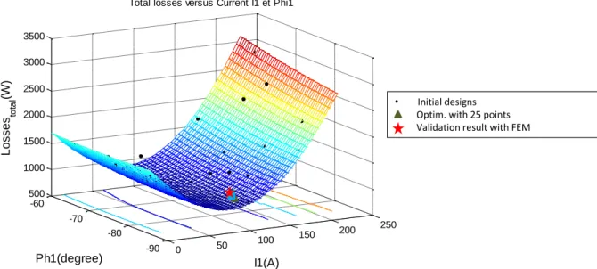
An initial set of 25 designs was chosen using the full factorial design. The set of designs were then evaluated in parallel on the available computer cores by the FEM. The Kriging models for each objective and constraint functions are built individually using the initial points. Fig. 1 presents the Response Surface (RS) of the total losses function for this optimization problem. The initial set of 25 designs is marked with the black dots. The optimal solution of this model (green triangle in Fig. 1) was sought using algorithm Sequential Quadratic Programming (SQP). The optimal solution was then validated using the FEM. According to the expert, the optimization result corresponds well the experiment. Another 25 points surrounded by the red dotted rectangle in Fig. 1 around the optimal one are selected and evaluated by the FEM. The new Kriging models for the objective
and the constraints functions are then fitted with the 50 points. The optimal solution with the new models is presented in Fig. 1 by the blue square.
Figure 1. Kriging model and Optimization results
The model of the objective function presented in Fig.1 is complex. Therefore the exploration surrogate model strategy is employed. The EGO algorithm is then used on the Kriging model with 50 initial points. Instead of direct optimization with the surrogate model, the EGO algorithm maximizes the Expected Improvement (EI) in order to find the infill point which allows improving the model in the most incertitude zone. Once a point found, it is then evaluated with the FEM and added to the set of sampled data in order to build new Kriging models on the increased data set. The model accuracy increases progressively with the increase of the sample data. The algorithm stops when the stop criterion is satisfied, returning the final optimal solution which is validated by the FEM. Considering the time consuming FEM model, a total budget of 50 fine model evaluation is imposed. The final solution with EGO algorithm is marked by the red star.
With the set of 25 points, no solution was found with all the constraints. A modification of voltage constraint to 100 V instead of 70V was then chosen and allows finding a solution (I1, 1) = (114.16, -80.3) that
verifies the constraints with acceptable tolerance (9886W for the power instead of 10 000W). After adding 25 points around the initial optimal solution, a new optimization with these 50 points is done with the voltage constraint of 70 V. An optimal solution is found with the respected constraints (I1, 1)=(144.3, -82.2).
The table 1 presents a comparison. For each optimal value (I1,1) found by Kriging model for a set of
25 or 50 points, the values of Power, Losses and Voltage are given using at first the Kriging model (square in grey) and secondly the FEM model (underlined). Relative errors are then provided in order to compare result obtained with Kriging model to those calculated with FEM, FEM results being taken as reference.
With the set of 25 points, it appears that the Kriging model leads to an error of more than 30% for the power and rotor losses. With the set of 50 points which allows verifying the voltage constraint of 70V, the error is weak for all variables except of the power (50.9%).
With EGO, the solution (I1, 1)=(142.9, -75.9) is verifying all the constraints if a tolerance of 2.5V (less
than 5%) is accepted for the voltage.
Table 1. Optimal solution with the first optimization problem
I1 (A) 1 (°) Power (W) Lossesrotor (W) Lossesstator (W) Uphase (V) Total losses (W) 25 points 114.16 -80.3 9886 384.8 657.9 100 956.9 7456 288.6 641.6 109.6 930.2 32,6% 33,3% 2,5% -8,8% 2,9% 50 points 144.30 -82.2 9886 394.9 783.3 70 1174.3 6551 376.3 798.7 71.1 1149.2 50,9% 4,9% -1,9% -1,5% 2,2% Final solution (with EGO) 142.90 -75.9 10020 379.7 798.7 72.5 1178.5 0 50 100 150 200 250 -100 -50 0 0 1000 2000 3000 4000 5000 I(A) Phi(theta) T o ta l los s e s (W ) • Initial designs
Optim. first problem with 25 points Optim. first problem with 50 points Optim. result with EGO
Analysis of results of optimization process shows that the voltage constraint is the most pregnant. As consequence, it has been decided to explore the impact of injecting third harmonic currents in order to attenuate the pressure due to the DC bus voltage. In the following part, the optimization on the second problem will be presented. The same constraints and objective are presented; nevertheless, there are four design variables instead of two 2 ones.
Optimization problem with 4 design variables
a) Problem formulation
Five-phase structure adds a freedom degree to the control strategy of synchronous machine by allowing injecting the 3rd harmonic of current. This property increases the number of input parameters in flux weakening strategy from two, in the case of 3-phase machine (fundamental current amplitude and phase
I1,1
), to four in the case of 5-phase machine
I1,1,I3,3
[1]. The added parameters can have a remarkable effect on iron and magnet losses in concentrated windings structure especially with the influence of iron nonlinearity. The optimization problem with 4 design variables is presented in Eqn. (5). The both optimization problems (1) and (5) have the same objective and constraints.(5) min ( ) 3 3 1 1, , , Losses Total I I s.t. , Power10kW, Losses W
rotor 400 , Lossesstator 800W , max
Uphase
70V With
0,230
( ),
85, 60
( ),
0,25 ( ),
0,90 ( ) 3 3 1 1 A Degree I A Degree I b) Exploitation surrogate model optimization
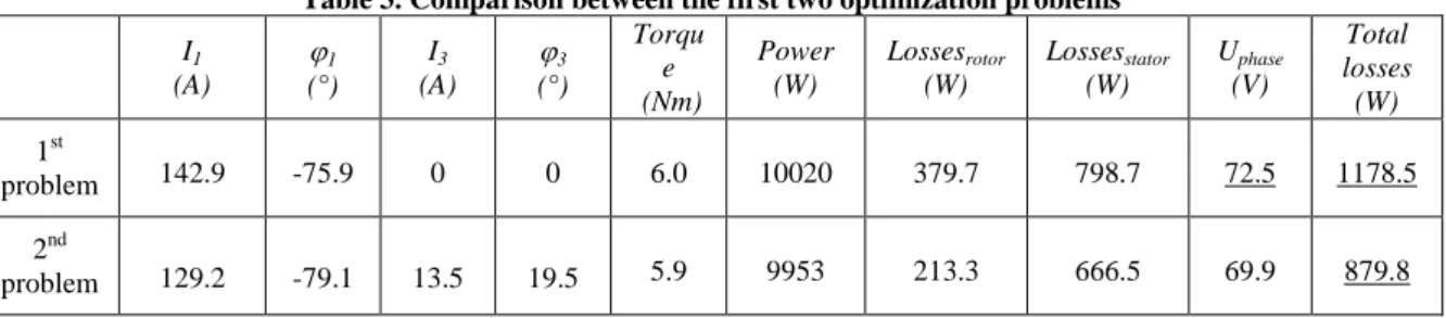
As in the first optimization problem, a first set of 25 points is selected. The Kriging model of the objective function with the 25 initial designs (black points) is presented in Fig. 2. As we can see that the Kriging model with four design variables is less complicated than the previous one with two design variables. The first optimal solution of this model (green triangle in Fig. 2) is sought using algorithm Sequential Quadratic Programming (SQP) with multi-start strategy. The solution validated by FEM is marked with a red filled star. The both solutions (Kriging model and FEM) are very close, and the Kriging model can be considered sufficiently accurate. The exploitation surrogate model optimization strategy is hence chosen for this problem. It means that the infill points at the optimum predicted by the surrogate model will be progressively added to the sampling plane.
Figure 2. Kriging model with 25 samples and Optimization results with 4 design variables
The table 2 presents the improvement process of optimization by iteration. The comparison between the optimal solutions and the FEM evaluation result underlined at the optimum is presented respectively in the table 2. All the optimal solutions respect the constraints, but the FEM results are not satisfied until the one with 45 points. The first line presents the results with 25 points, and both the torque and the voltage constraints are not respected. After adding 10 points to the sampling plane, only the voltage constraint (less than 70V) is not respected.
rpm Speed 16000
• Initial designs Optim. with 25 points Validation result with FEM
0 50 100 150 200 250 -90 -80 -70 -60 500 1000 1500 2000 2500 3000 3500 I1(A)
Total losses versus Current I1 et Phi1
Ph1(degree) L o sse s to ta l (W )
Table 2. Optimal solution with the first optimization problem I1 (A) 1 (°) I3 (A) 3 (°) Power (W) Lossesrotor (W) Lossesstator (W) Uphase (V) Total losses (W) 25pts 126.7 -78.4 15.02 30 9886 202.0 643.6 70 845.6 9684 201.2 677.9 72.5 879.0 2,1% 0,4% -5,1% -3,4% -3,8% 35pts 128.4 -78.4 13.93 25.7 9886 207.9 648.6 70 870.3 10941 209.5 662.6 72.1 872.2 -9,6% -0,8% -2,1% -2,9% -0,2% 45pts (final) 129.2 -79.1 13.48 19.5 9953 213.3 666.4 69.93 879.6 9953 213.3 666.5 69.91 879.8
The exploitation surrogate model optimization allows finding the feasible solution for the 4 design variables.
c) Comparison and conclusion between the two problems.
The two optimization problems are compared in this part. The table 3 presents the comparison between the optimal solutions. By injecting the 3rd harmonic currents, the voltage constraint is respected while the mechanical torque is kept. Furthermore, the total losses in the machine decrease 25%. The comparison can well illustrate the advantages for 5-phase machines to inject third-harmonic component.
Table 3. Comparison between the first two optimization problems
I1 (A) 1 (°) I3 (A) 3 (°) Torqu e (Nm) Power (W) Lossesrotor (W) Lossesstator (W) Uphase (V) Total losses (W) 1st problem 142.9 -75.9 0 0 6.0 10020 379.7 798.7 72.5 1178.5 2nd problem 129.2 -79.1 13.5 19.5 5.9 9953 213.3 666.5 69.9 879.8 Two optimization strategies are employed respectively for the two problems: exploration surrogate model optimization and exploitation one. The choice of the most appropriate optimization strategy depends on the model complexity. If the model to be approximated is smooth and not complex, the exploitation strategy (RS) can be employed; otherwise the exploration one (EGO) should be used.
OPTIMAL SHAPE DESIGN OF 5-PHASE HIGH SPEED MACHINE
The flux weakening control strategy is accomplished in the previous part. In this part, the shape design optimization is presented.
a) Optimization problem formulation with 6 design variables
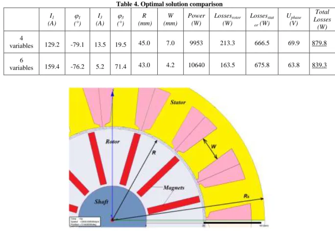
The objective of this part is to optimize design of the 5-phase high speed machine. Compared to the 4 design variables optimization problem, two dimension variables are added in order to take into account the machine structure optimization: the rotor radius and the stator tooth width (tooth width + slot width =constant) (see Fig. 3). Both added parameters have remarkable effects on the objective function. The increase of the rotor radius decreases the height of the stator slots causing more copper losses (smaller copper section), and vice versa. The increase of the stator slot width (by decreasing the tooth width) expands the copper section leading to less copper losses. Furthermore, the machine magnetic structure depends widely on the two optimized dimensions which gives these parameters an important influence on the machine torque and eddy-current losses. The same objective and constraints are considered compared to the two precedent problems. The optimization problem is presented in Eqn. (6): (6) min ( ) , , , , ,1 3 3 1 Losses Total W R I I s.t. , Power10kW, Losses W
rotor 400 , Lossesstator 800W , max
Uphase
70Vrpm Speed 16000
With
0,230
( ),
85, 60
( ),
0,25
( ),
0,90 ( ),
35,60
( ),
3,13( ) 3 3 1 1 A I A R mm W mm I Where R – the radius of rotor, W – the stator tooth width. b) Optimization design using EGO algorithm
As the number of design variables increases, it is difficult to have an accurate surrogate model. There are two approaches to enhance the accuracy of surrogate model: increase the sampling points and use the appropriate sampling strategy. In our case, an initial set of 70 points using Latin Hypercube strategy is selected for the 6 design variable problem. The EGO algorithm is used in order to obtain a global optimum and have an accurate surrogate model around the optimum. A total budget of 200 fine model evaluations is imposed during the EGO optimization process.
The table 4 presents the comparison results between the 4 and 6 design variable problems. The initial dimension parameters are considered for problem with four variables.
Table 4. Optimal solution comparison
I1 (A) 1 (°) I3 (A) 3 (°) R (mm) W (mm) Power (W) Lossesrotor (W) Lossesstat or (W) Uphase (V) Total Losses (W) 4 variables 129.2 -79.1 13.5 19.5 45.0 7.0 9953 213.3 666.5 69.9 879.8 6 variables 159.4 -76.2 5.2 71.4 43.0 4.2 10640 163.5 675.8 63.8 839.3
Fig. 3 Studied machine structure with the two optimized dimensions (R, W)
After adding two dimension parameters, the high speed machine can improve notably the performance at the optimal solution. The critical rotor losses are reduced (23%) while all the constraints are respected. Moreover the final optimal solution can work with lower DC voltage bus supply (-9%) and higher mechanical power (+7%).
CONCLUSIONS
The optimization results prove the remarkable effect of using the freedom degree offered by a 5-phase structure on iron and magnets losses. Whereas, by injecting relatively low 3rd harmonic of current (~10% of fundamental) total losses are notably reduced (25%). Moreover, due to this optimization procedure rotor losses are decreased far below the imposed limit (47%), which makes the machine well protected against magnet demagnetization. An optimization with EGO algorithm is ongoing, which will allow obtaining progressively the optimal solution of the FEM with small evaluation budget. Combining with two geometric parameters, a more complex optimization control problem is formulated and resolved. The performances of the 5-phase machine with concentrated windings are notably improved at high speed (16 000 rpm).
REFERENCES
[1] S. Sadeghi, L. Parsa, "Multiobjective Design Optimization of Five-Phase Halbach Array Permanent-Magnet Machine," IEEE Trans. on Magnetics, vol.47, no.6, pp.1658-1666, June 2011
[2] Xiaoyan Huang, A. Goodman, C. Gerada, Youtong Fang, Qinfen Lu, "Design of a Five-Phase Brushless DC Motor for a Safety Critical Aerospace Application," IEEE Trans. on Industrial Electronics, vol.59, no.9, pp.3532-3541, Sept. 2012
[3] L. Parsa, H.A. Toliyat H.A., "Fault-Tolerant Interior-Permanent-Magnet Machines for Hybrid Electric Vehicle Applications," IEEE Trans. on Vehicular Technology, vol.56, no.4, pp.1546-1552, July 2007
[4] E. Levi, “Multiphase Electrical Machines for Variable-Speed Applications”, IEEE Transactions on Industrial Electronics, Vol. 55, No. 5, May 2008.
[5] L. Lu, B. Aslan, L. Kobylanski, P. Sandulescu, F. Meinguet, X. Kestelyn, E. Semail, « Computation of Optimal Current References for Flux-weakening of Multi-Phase Synchronous Machines”, IEEE IECON’2012, International Conference On Industrial Applications of Electronics, September 2012, Montreal (Canada)
[6] A.M El-Refaie, "Fractional-Slot Concentrated-Windings Synchronous Permanent Magnet Machines: Opportunities and Challenges", IEEE Trans. on Industrial Electronics, Vol. 57, No. 1, January 2010.
[7] Seok-Hee Han; Soong, W.L.; Jahns, T.M.; , "An Analytical Design Approach for Reducing Stator Iron Losses in Interior PM Synchronous Machines During Flux-Weakening Operation," Industry Applications Conference, 2007. 42nd IAS Annual Meeting. Conference Record of the 2007 IEEE , vol., no., pp.103-110, 23-27 Sept. 2007
[8] Yamazaki, K.; Fukushima, Y.; , "Effect of Eddy-Current Loss Reduction by Magnet Segmentation in Synchronous Motors With Concentrated Windings," Industry Applications, IEEE Transactions on , vol.47, no.2, pp.779-788, March-April 2011
[9] Chong, L.; Dutta, R.; Rahman, M.F.; Lovatt, H.; , "Experimental verification of core and magnet losses in a concentrated wound IPM machine with V-shaped magnets used in field weakening applications," Electric Machines & Drives Conference (IEMDC), 2011 IEEE International , vol., no., pp.977-982, 15-18 May 2011
[10] Jiunn-Jiang Chen; Kan-Ping Chin; , "Minimum copper loss flux-weakening control of surface mounted permanent magnet synchronous motors," Power Electronics, IEEE Transactions on , vol.18, no.4, pp. 929- 936, July 2003
[11] S.M. Sue, C.T. Pan, “Voltage-Constraint-Tracking-Based Field-Weakening Control of IPM Synchronous Motor Drives,” IEEE Trans. Ind. Electron., vol. 55, no. 1, pp. 340-7, January 2008.
[12] Seung-Ki Sul, “Control of Electric Machine Drive System”, IEEE Press Series on Power Engineering, John Wiley & Sons Ltd, chap 5, 2011
[13] L. Parsa, N. Kim and H. Toliyat, “Field Weakening Operation of a High Torque Density Five Phase Permanent Magnet Motor Drive,” IEEE International Electric Machines and Drives Conference, pages 1507-1512, May 2005.
[14] Z. Sun, J. Wang, W. Jewell, D. Howe, “Enhanced Optimal Torque Control of Fault-Tolerant PM Machine Under Flux-Weakening Operation”, IEEE Trans. Ind. Electron., vol. 57, no. 1, pp. 344-353, Jan. 2010.
[15] L. Lu, E. Semail, L. Kobylanski, X. Kestelyn, “Flux-Weakening Strategies for a Five-Phase PM Synchronous Machine”, EPE 2011 (European Power Electronics Congress), Birmingham ,UK, September 2011,
[16] S. Xuelei, W. Xuhui, C. Wei , "Research on field-weakening control of multiphase permanent magnet synchronous motor," Electrical Machines and Systems (ICEMS), 2011 International Conference on , vol., no., pp.1-5, 20-23 Aug. 2011, Beijing (China)
[17] L. Chedot, G. Friedrich, J.-M. Biedinger, P. Macret, “Integrated Starter Generator: The Need for an Optimal Design and Control Approach. Application to a Permanent Magnet Machine," Industry Applications, IEEE Transactions on , vol.43, no.2, pp.551-559, March-april 2007
[18] http://www.ansys.com/Products/Simulation+Technology/Electromagnetics/Electromechanical+Design/ANSYS+Maxwell last access 19 09 2012
[19] S. Giurgea, H. S. Zire, and A. Miraoui, Two Stage Surrogate Model for Finite-Element-Based Optimization of Permanent-Magnet Synchronous Motor, IEEE Transaction on Magnetics, Vol. 43, No. 9, September 2007
[20] J. Gong, A. Berbecea, F. Gillon, P. Brochet, “Optimal Design of a Double-sided Linear Induction Motor using an Efficient Global Optimization”, International Symposium on Linear Drives for Industry Applications, LDIA2011, Eindhoven, Netherlands.
[21] A. C. Berbecea, S. Kreuawan, F. Gillon, and P. Brochet, A parallel multi-objective efficient global optimization: the finite element method in optimal design and model development, IEEE Transaction on magnetics, Vol. 46, No. 8, ISSN 0018-9464, August 2010. [22] M. Schonlau, W. J. Welch, and D. R. Jones, “Global versus local Search in constrained optimization of computer models”, IMS
lecture notes, Vol. 34, 1988, pp. 11-25.
[23] S. Kreuawan, “Modeling and optimal design in railway applications”, Ph.D. dissertation, Ecole Centrale de Lille, Lille, France, 2008, on line available: http://tel.archives-ouvertes.fr/index.php?halsid=5oc95e2243gc3k9gestnu5km27&view_this_doc=tel-00363633&version=2
[24] S. Kreuawan, F. Gillon, and P. Brochet, “Efficient global optimization an efficient tool for optimal design”, In proceeding of 16th International Conference on the Computation of Electromagnetic Fields (Compumag), Aachen, Germany,2007.
[25] A. Forrester, A. Sóbester, A. Keane, “ Engineering Design via Surrogate Modeling”, A John Wiley and Sons, Ltd., Publication, 2008, ISBN: 978-0-470-06068-1
[26] J. Sacks, W. J. Welch, T. J. Mitchell, and H. P. Wynn, “Design and analysis of computer experiments,” Statistical Science, Vol. 4, No. 4, pp. 409-435, 1989.
APPENDIX
Basis of the Kriging method
Kriging method was first developed by D. Krige and was introduced in field of computer science and engineering by Sacks et Al [10]. In Kriging model, an unknown function ycan be expressed as in (7):
(7) yB
x Z xwhere B(x) is a regression or polynomial model, giving the global trend of the modeled function y, and Z(x), which is a model of stochastic process, gives the local deviations from the global trend. The Gaussian correlation function is chosen in order to control the smoothness of the model.
The mean square error (MSE) is the expected value of difference between the true response and the estimated one. By minimizing the expected MSE, the expression for the Kriging model is:
(8) yˆ(x)fBˆrTR1
yfBˆwhere