Science Arts & Métiers (SAM)
is an open access repository that collects the work of Arts et Métiers Institute of Technology researchers and makes it freely available over the web where possible.
This is an author-deposited version published in: https://sam.ensam.eu Handle ID: .http://hdl.handle.net/10985/9089
To cite this version :
Benoit AUGIER, Patrick BOT, Frédéric HAUVILLE, Mathieu DURAND - Fluid Structure Interaction of Yacht Sails in the Unsteady Regime - 2013
Any correspondence concerning this service should be sent to the repository Administrator : [email protected]
Fluid Structure Interaction of Yacht Sails in the Unsteady Regime
Benoit Augier1, Patrick Bot1, Frederic Hauville1, Mathieu Durand1,2 1 Research Institute of the Naval Academy, France
2 Company K-Epsilon, France
Abstract
The dynamic Fluid Structure Interaction (FSI) of yacht sails submitted to a harmonic pitching motion is numerically investigated to address both issues of aerodynamic unsteadiness and structural deformation. The model consists in an implicit dynamic coupling algorithm between a Vortex Lattice Method model for the aerodynamics and a Finite Element Method model for the structure dynamics. It is shown that the dynamic behaviour of a sail plan subject to yacht motion clearly deviates from the quasi-steady theory. The aerodynamic forces oscillate with phase shifts with respect to the motion. This results in hysteresis phenomena, which show aerodynamic equivalent damping and stiffening effects of the unsteady behaviour. The area of the hysteresis loop corresponds to the amount of energy exchanged by the system and increases with the motion reduced frequency and amplitude. In the case of a rigid structure, the aerodynamic forces oscillations and the exchanged energy are lower than for a flexible structure.
Nomenclature
VBS VTW VAW Vr AW TW βAW βeff φ θ za A T S C Cx Cy Boat Speed True Wind Speed Apparent Wind Speed Reduced Velocity Apparent Wind True wind angle Apparent wind angle Effective wind angle Heel angleTrim angle
Pitching angular velocity
Height of the centre of aerodynamic forces Oscillation amplitude
Oscillation period
Total sail surface (jib + main sail) Total sail plan chord at za
Driving force coefficient Heeling force coefficient
m.s-1 m.s-1 m.s-1 - - deg deg deg deg deg rad.s-1 m deg s m2 m - -
1 Introduction
Sails are soft structures which have shapes that change according to the aerodynamic loading. The resulting modified shape affects the air flow and thus, the aerodynamic loading applied to the structure. This so-called Fluid Structure Interaction is strong and
non-linear, because sails are soft and light membranes which experience large displacements and accelerations, even for small stresses. As a consequence, the actual sails shape while sailing -the so-called flying shape- is different from the design shape defined by the sail maker and is generally not known. Recently, several authors have focused on the Fluid Structure Interaction (FSI) problem to address the effect of the structural deformation on the flow and hence the aerodynamic forces generated [1][2].
Traditional Velocity Prediction Programs (VPPs) used by yacht designers consider a static equilibrium between hydrodynamic and aerodynamic forces. Hence, the force models classically used are estimated on a steady-state. However, in realistic sailing conditions, the flow around the sails is unsteady, mainly because of the yacht motion due to waves. To account for this dynamic behaviour, several Dynamic Velocity Prediction Programs (DVPPs) have been developed (e.g. [3][4][5]) which need models of dynamic aero and hydrodynamic forces. While the dynamic effects on hydrodynamic forces have been largely studied, the unsteady aerodynamic behaviour of the sails has received much less attention. In a quasi-static approach, a first step is to add the velocity induced by the yacht motion to the steady apparent wind to build an instantaneous apparent wind [4][5] and consider the aerodynamic forces corresponding to this instantaneous apparent wind using force models obtained in the steady state. In a recent study, Gerhardt et al. [6] developed an analytical model to predict the unsteady aerodynamics of interacting yacht sails in 2D potential flow and performed 2D wind tunnel oscillation tests. Shoop et al. [7] first developed an unsteady aero-elastic model in potential flow dedicated to flexible membranes but neglected the inertia. Recently, Fossati et al. [8][9] studied the aerodynamics of model rigid sails in a wind tunnel, and showed that a yacht pitching motion has a strong and non-trivial effect on aerodynamic forces. They showed phase shifts and hysteresis phenomenon between the aerodynamic forces and the oscillating apparent wind, highlighting strong deviations from the quasi-static analysis.
In this paper, the effects of unsteadiness and structure deformation on a 8m yacht sail plan are analysed thanks to numerical experimentation. The numerical model corresponds to a J80 class yacht with her standard rigging and sails designed by the sail maker DeltaVoiles. An unsteady FSI model has been developed and validated with experiments in real sailing conditions [10]. The model is used to investigate a rig’s behaviour under a harmonic pitching forcing. The numerical model
is presented in section 2. Section 3 describes the methodology of the numerical investigation. The results are presented in section 4, while concluding remarks and ideas for future work are given, with.
2 Numerical model
To study the aero-elastic problem of yacht sails, a fluid-structure numerical model has been developed by coupling an inviscid flow solver (AVANTI) and a structural solver (ARA). The coupled ARAVANTI software can model a yacht rig in order to predict forces, tensile and shape of sails according to the wind loading in dynamic conditions. The numerical models and coupling are briefly described below. For more details, the reader is referred to [11] for the fluid solver AVANTI and to [12] for the structural solver ARA and the FSI coupling method.
Fluid solver
Flow modelling is based on the vortex lattice method (VLM). This method is suitable for external flows where vorticity exists only in the boundary layers on the lifting surface and its wake. In the lifting surface model, the vorticity is represented by a non-planar dipole distribution along the lifting surface and the wake formed by the vortex shedding at the trailing edge is represented by a vortex sheet. This method is basically made of two parts: a lifting body problem and a wake problem. These two problems are coupled by means of a kind of Kutta condition that has been derived from the kinematic and dynamic conditions along the separation lines. Usually, these lines are reduced to the trailing edges although more complicated situations have been sometimes considered. Except when writing this Kutta condition, the flow has been assumed to be inviscid. The lifting problem is solved by means of a boundary integral method: the surface of the body is represented using panels of rectangular shape which are used to satisfy the potential slip conditions. Specifically, a dipole strength was associated with each panel, and the strength of the dipole was adjusted by imposing that the normal velocity component at the surface of the body must vanish at control points. The wake has been modelled by means of the particles method itself developed by Rehbach [13] and then Huberson [14]. According to this method, the vorticity distribution within the wake is described by means of virtual particles carrying vortices. The motion of particles is computed in a Lagragian framework. The vorticity on each particle has to satisfy the Helmholtz equation. Dissipation of the wake is modelled by damping (empirically adjusted [14]) of the particles intensity in time. For the incoming flow, the true wind is defined with the velocity at 10m height and an atmospheric wind gradient is considered. Boat speed and motion are then considered to determine the apparent wind.
This fluid model has been largely used and validated [15]. As the fluid is supposed to be inviscid, the validity of the model is obviously limited to mostly attached
flows, as it is the case for a sailing yacht on a close hauled course. The viscous drag is not considered in the simulations.
Structural solver
The structure model is a finite element model composed of beams (spars and battens), cables (shrouds and running rigging) and membranes (sails). The sail model is based on CST (Constant Strain Triangles) membrane model elements extended in 3 dimensions. Despite its simplicity, this choice has proven to give a good ratio of accuracy to computing power. The assumptions imposed inside this element are constant stresses, constant strains and uniform stiffness of the material. Non-linearities coming from the geometry and compressions are taken into account. The nonlinear finite element formulation based on the virtual work equation links the variation of forces to the variation of displacement. The Newmark-Bossak Interaction scheme (temporal discretization) is based on a prediction-correction iterative method. Finertial+Fdamping+Fstiffness +Fexternal R (1)
Deriving these as a function of position, speed and acceleration results in a Newton-type scheme:
M
.
u
+
C
.
u
+
K
.
u
=
R
(2) The Newmark scheme puts position, speed and acceleration in the following relation:R
u
K .
*
(3a) K t C t M K* . 12 . (3b)Where [M] is the inertia matrix (mass and fluid added mass), [C] is the damping matrix and [K] is the stiffness matrix. In the stress-strain relationship of the sail fabric, an anisotropic composite material is considered and the properties of several layers may be superimposed in the matrix [K] (films and strings for example).
The sails structure and panelling are imported from the sail designer software Sailpack which was used to make the sails and the structural mesh is built according to the sail design. Mechanical properties of every components of the structure have been experimentally measured.
Fluid structure coupling
The effects of the interaction are translated into a coupling of the kinematic equation (continuity of the normal component of the velocity at the interface between fluid and structure geometrical domains) and dynamic equations (continuity of the normal component of the external force, pressure forces, on the contact surface of the sail with the fluid). An implicit iterative algorithm is used to coordinate the data exchanges between the fluid and structure solvers and to obtain a stable coupling. Two different meshes are used to satisfy the quality criteria of fluid mesh on one side and structural mesh on the other side. The deformation from the structural computation is introduced into the fluid
mesh. Then new forces from the fluid computation are interpolated in the structural code by a consistent method. In a previous work, much attention has been devoted to the validation of this FSI model with respect to full scale experiments [10]. The results showed a good agreement between the simulation and experiment, and the small observed discrepancies were mainly attributed to difficulties to determine precisely the environmental conditions and some inaccuracies in the mechanical properties of the structure elements.
3 Numerical investigation method
a) b)
Figure 1: a) References frame and motion, b) Dynamic wind triangle with pitching motion
The yacht reference frame and the coordinate system are illustrated in Figure 1.a. A steady state computation is run first in order to find the converged equilibrium state to define the sails flying shape without yacht motion. The sailing parameters are the following: true wind speed at a 10m height VTW=6.7 m.s-1, true wind angle TW=40°,
boat speed VBS=2.6 m.s-1, heel angle φ=20° and trim
angle . Thanks to this steady state computation, the converged equilibrium state is found, which is used as the initial condition for the computations with pitching forcing. The altitude of the centre of aerodynamic forces is used to define the flow characteristic quantities: apparent wind speed VAW, apparent wind angle βAW and
sail plan chord C. The apparent wind angle AW is
corrected from the effects of a constant heel and trim according to the effective wind angle theory (first introduced by Marchaj [16]) in ordre to obtain the effective apparent wind angle eff (see Jackson [17] for
heel effect, and Fossati et al. [8] for pitch effect):
cos cos tan tan1 AW
eff (4)
From the converged steady state, an harmonic pitching forcing is imposed to the rig characterized by the oscillation amplitude A and period T.
t T
Acos 2 (5) The motion is gradually imposed by applying a ramp which smoothly increases from 0 to 1 during the first 3s
of imposed motion (see first period in Fig. 2), in order to avoid discontinuities in the acceleration. The investigation has been made in the range A=3 to 6° and T=1.5 to 6s corresponding to the typical environmental conditions encountered, as shown in the experiment of [10].
Due to the pitching motion, the apparent wind experienced by the sails is periodically modified as the rotation adds a new component of apparent wind. Following the analysis of Fossati et al [8], the apparent wind and pitch-induced velocity are considered at the centre of aerodynamic forces height za. This yields time
dependent apparent wind speed and angle, given by: VAW(t) VTWsin TW ² VTWcos TW VBS za(t)² (7a)
) ( sin sin ) ( 1 t V V t AW TW TW AW (7b)
And hence the time dependent effective wind angle:
cos cos tan tan1 t t t AW eff (8)
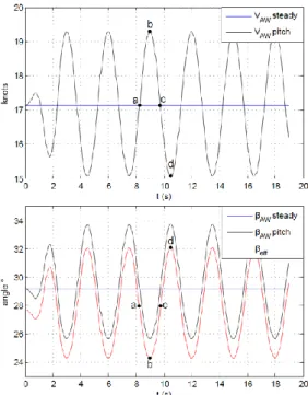
Figure 1.b shows the dynamic vector composition for pitch velocity = max, 0 and min. As shown on Fig. 2,
the apparent wind angle variations (equation 8) are in phase opposition with the apparent wind speed (equation 7).
Figure 2: Time dependent apparent wind speed and angles resulting from pitching oscillation with period T=3s and amplitude A=5°.
The resultant aerodynamic force is projected on the yacht reference frame (Fig. 1.a), in order to get the driving (Fx) and the heeling (Fy) forces. Driving and heeling forces are converted in non-dimensional coefficients in the following way:
) ( 5 . 0 ) ( ; ) ( 5 . 0 ) ( 2 2 t SV Fy t Cy t SV Fx t Cx AW AW (9) where S is the total sail area and ρ is the fluid density.
The unsteady character of a flow is usually characterized by the reduced velocity Vr (or the reduced frequency fr)
defined by: 1 r AW r C f T V V (6)
The pitching period values investigated correspond to a reduced velocity Vr from 2 to 8.5 (reduced frequency fr
from 0.12 to 0.47), which is a similar dynamic range than the experiments of Fossati et al [8].
4 Results
The variations of the aerodynamic force coefficients Cx(t) and Cy(t) with the instantaneous apparent wind angle are analysed for the different values of pitching frequency and amplitude investigated. The cases of varying frequency and constant amplitude are shown in Figure 3, and Figure 4 presents different values of pitching amplitude for a constant frequency.
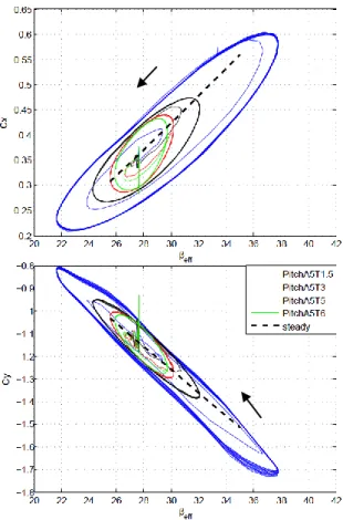
Figure 3: Driving and heeling force coefficients vs βeff(t) at
different pitching periods T=1.5, 3, 5 and 6s with a 5° amplitude. The rotation direction is shown by the arrows. The steady state variation with βeff is also shown.
From the initial condition corresponding to the reference steady state at βeff(0)=27.8°, the system oscillates under
the pitching forcing in a periodic behaviour as shown by the quasi-elliptic limit cycle drawn on the figure. The
initial peak at the beginning of the run is due to imperfection of the restart by the dynamic computation from the reference steady state. It is noticeable that the periodic behaviour is reached after a short transient time of the order of the smoothing ramp applied on the motion initiation. The evolution of Cx and Cy with βeff in a
steady case, obtained from steady computations for different βeff is also shown for comparison. The
hysteresis loop denotes the existence of a phase shift between aerodynamic forces and βeff(t). The enclosed
area represents the amount of energy that can be dissipated or gained from the pitching motion. As the reduced velocity decreases (shorter period), the area of the hysteresis loop highly increases as the range of wind angle swept under pitching ( βeff) gets wider, and the
slope of the hysteresis loop decreases. These results are very similar to the experimental results obtained by Fossati et al. [8]. Limit cycles show the same trends, centered on the steady state trend, with an increasing driving force and a decreasing heeling force (Cy>0) when βeff(t) is increasing.
Figure 4: Driving and heeling force coefficients vs βeff(t) at
different pitching amplitudes A=3, 5 and 6° with a 5s period T. The rotation direction is shown by the arrows. The steady state variation with βeff is also shown.
For a given pitching frequency, the area of the hysteresis loop is noticeably increased by the higher pitching amplitude (Fig 4). Although the reduced velocity is not changed, the amplitude has a strong effect on the unsteady character of the system as the rotation velocity is directly linked to the oscillation amplitude. Increasing
the pitching period moves the ellipse centre towards lower values of βeff(t) and force coefficient. The pitch
amplitude also has a great influence on the hysteresis loop enclosed area. When the pitching amplitude is increased, the variation range of aero forces, variation range of βeff(t) and the mean of βeff(t) increase.
Rigid versus flexible structure
In order to analyse the contribution of the fluid structure coupling in the aero-elastic system, numerical experimentation has also been conducted with a rigid structure. The rigid structure is the converged flying shape calculated from the FSI steady simulation, which is maintained unchanged for the unsteady fluid only simulation with pitching forcing.
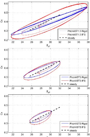
Figure 5: Comparison of rigid and flexible structures: Driving force coefficient vs βeff(t) at different pitching periods T=1.5, 3
and 5s at 5° amplitude. The steady state variation with βeff is
also shown.
Figure 5 shows the evolution of the calculated driving force coefficient Cx(t) for both FSI and fluid only simulations. The enclosed area is smaller and the loop axis slope is slightly lower in the rigid structure case. Fluid only calculation underestimates the damping effect and the stress variation. The same behavior is observed for the side force coefficient Cy(t) (not shown here). The variation range of the aerodynamic coefficients is
underestimated by the fluid only calculation, highlighting the importance of FSI simulation in the case of yacht sails.
5 Conclusions
The unsteady fluid structure interaction of yacht sails and rig under harmonic pitching has been investigated in order to highlight both contributions of dynamic behaviour and fluid structure interaction on a sail plan in realistic conditions. The model is made of a vortex lattice fluid model and a finite element structure model which are coupled with an implicit algorithm allowing for dynamic simulations. This model has been previously validated with full scale experiments in upwind real conditions [10]. The combination of pitching motion, yacht velocity and true wind gives rise to a time dependent apparent wind. The sail plan centre of effort has been chosen as reference and the variations of the resultant aerodynamic forces have been analysed as a function of the dynamic apparent wind angle, according to the analysis introduced by Fossatti et al. [8]. Similarly to the experimental results of [8], the aerodynamic coefficients plotted against the instantaneous apparent wind angle exhibit an hysteresis loop, showing that unsteady conditions lead to aerodynamic equivalent damping and stiffening effects and that the dynamic behaviour of a sail plan subject to pitchin deviates from the quasi-steady theory. The phase shifts and hysteresis loop area increase with the motion reduced frequency and amplitude.
The great influence of the fluid structure interaction has been highlighted by comparison between both rigid and flexible structures. The oscillation amplitude of the aerodynamic forces is higher in the case of a flexible structure than for a rigid structure. It would be interesting to address this issue for different structure mechanical characteristics. For example, the dynamic FSI model may be used to study the effect of different tensions in the rig for different dynamic sailing conditions, which may be useful for rig design purposes and to make racing tuning guides.
To better understand the FSI dynamics of sails, more simulations and experimental work would be needed to investigate in more details the relative contributions of aerodynamics and structural dynamics. It would be also interesting to explore a wider range of forcing in terms of oscillation period and amplitude, as well as other excitations such as roll and yaw motion.
Acknowledgements
The authors are grateful to Prof. Fossati of Politecnico di Milano for valuable discussions and to the K-Epsilon company for continuous collaboration. This work was supported by the French Naval Academy.
References
1. Chapin, V., Heppel, P., “Performance optimization of interacting sails through fluid structure coupling”.
International Conference on Innovation in High Performance Sailing Yachts, Lorient, France, 2010. 2. Renzsh, H., Graf, K., (2010) “Fluid structure interaction simulation of spinnakers getting closer to reality”. International Conference on Innovation in High Performance Sailing Yachts, Lorient, France, 2010 3. Masuyama, Y., Tahara, Y., Fukasawa, T., (1993) “Dynamic performance of sailing cruiser by full scale sea test”. the 11th Chesapeake Sailing Yacht Symposium, Annapolis, Maryland, USA, 1993.
4. Richardt, T., Harries, S., Hochkirch, K., (2005) “Maneuvring simulations for shops and sailing yachts using Friendship equilibrium as an open modular workbench.”. International EuroConference on Computer Application and Information Technology in the Maritime Industries, Hamburg, Germany, 2005 5. Keuning, J.A., Vermeulen, K.J.., de Ridder, E.J., (2007) “A generic mathematical model for the manoeuvring and tacking of sailing yacht”. The 19th Chesapeake Sailing Yacht Symposium, Annapolis, Maryland, USA, 2007.
6. Gerhardt, F. C.; Flay, R. G. J.; Richards, P. (2011): “Unsteady aerodynamics of two interacting yacht sails in two-dimensional potential flow”. J. Fluid Mech., 668. 551-581.
7. Schoop, H., Bessert, N. (2001) “Instationary aeroelastic computation of yacht sails. Int. J. Numer. Meth. Engng. 52, 787-803.
8. Fossati, F., Muggiasca, S., (2011), “Experimental investigation of sail aerodynamic behaviour in dynamic conditions”, Journal of Sailboat Technology, 2011,
2011(03)
9. Fossati, F., Muggiasca, S., (2010), “Numerical modelling of sail aerodynamic behavior in dynamic conditions”. International Conference on Innovation in High Performance Sailing Yachts, Lorient, France, 2010 10. Augier, B., Bot, P., Hauville, F., Durand, M., (2012) “Experimental validation of unsteady models for fluid structure interaction: Application to yacht sails and rig”. J. Wind Engng and Ind. Aero. 2012, 101, 53-66
11. Roux, Y., Huberson, M., Hauville, F., Boin, J.P., Guilbaud, M., Ba, M. (2002) “Yacht performance prediction: Toward a numerical VPP”. High Performance Yacht Design Conference, Auckland, December 2002, pp 11-20
12. Hauville, F., Durand, M., and Roux, Y., (2008), “Aero elastic model applied to the deformation of a rig”, European Journal of Environmental and Civil Engineering 2008, 12(5), 549-560
13. Rebhach, C., (1978) “Numerical calculation of three dimensional unsteady flows with vortex sheets”. AIAA, 16th Huntsville 1978, paper 1978-111.
14. Huberson, S., “Modélisation asymptotique et simulation numérique d'écoulements tourbillonnaire”. PhD thesis, Université Pierre et Marie Curie (ParisVI)- LIMSI-CNRS.
15. Charvet, T., Hauville, F., Huberson, S., “Numerical simulation of the flow over sails in real sailing conditions”. Journal of Wind engineering and Industrial Aerodynamics October 1996, 63(1-3), pp 111-129 16. Marchaj, C.A. (1996), Sail performance : techniques to maximize sail power, International Marine/Mc Graw-Hill, USA.
17. Jackson, P., (2002) “An Improved Upwind Sail Model for VPPs”. High Performance Yacht Design Conference, Auckland, December 2002, pp 11-20