Science Arts & Métiers (SAM)
is an open access repository that collects the work of Arts et Métiers Institute of
Technology researchers and makes it freely available over the web where possible.
This is an author-deposited version published in:
https://sam.ensam.eu
Handle ID: .
http://hdl.handle.net/10985/19396
To cite this version :
Sana CHAABANI, Pedro José ARRAZOLA, Yessine AYED, Aitor MADARIAGA, Albert TIDU,
Guénaël GERMAIN - Comparison between cryogenic coolants effect on tool wear and surface
integrity in finishing turning of Inconel 718 - Journal of Materials Processing Technology - Vol.
285, p.116780 - 2020
Any correspondence concerning this service should be sent to the repository
Administrator :
archiveouverte@ensam.eu
Comparison between cryogenic coolants e
ffect on tool wear and surface
integrity in
finishing turning of Inconel 718
S. Chaabani
a,b,*
, P.J. Arrazola
a, Y. Ayed
b, A. Madariaga
a, A. Tidu
c, G. Germain
baFaculty of Engineering, Mondragon Unibertsiatea, 20500 Mondragon, Spain
bArts et Métiers ParisTech, Campus d’Angers, LAMPA, 2 bd du Ronceray, 49035 Angers Cedex 1, France
cLaboratoire d’Étude des Microstructures et de Mécaniques des Matériaux (LEM3), CNRS Université de Lorraine, 57078 Metz Cedex 03, France
Keywords: Cryogenic machining Inconel 718 Surface integrity Tool wear A B S T R A C T
The most important challenges when machining difficult-to-cut alloys used in critical applications consist mainly in increasing tool life as well as improving the component surface integrity. In particular, the nickel based alloys exhibit very low thermal conductivity inducing higher cutting temperature and thereby rapid tool wear. In this context, cryogenic machining is a promising approach that enhances cooling efficiency either when using the liquid nitrogen LN2 or the carbon dioxide LCO2. According to previous works, cryogenic machining has been carried out on several work materials such as titanium alloys and nickel based alloys. Their findings figured out that longer tool life and better surface integrity were obtained when machining titanium alloys, unlike nickel based alloys. In this work, a comparative study has been carried out in order to investigate the cryogenic ma-chining performance during turning operation of Inconel 718 with respect to tool wear behavior and surface integrity of the machined part. In fact, two cryogenic fluids were employed namely LN2 and LCO2 considering as a reference the conventional lubrication. This study illustrates that conventional lubrication and LCO2cryogenic cooling allowed to obtain similar machining time, tool wear and surface finish. Nevertheless, LN2 cryogenic machining resulted in the lowest tool life as well as the poorest surface finish. Moreover, residual stresses have been measured beneath the machined surfaces when machining using new tools and tools with different levels of tool flank wear. It was observed that compared to conventional lubrication, both cryogenic conditions showed better results with respect to residual stress profiles along the machined surfaces.
1. Introduction
Inconel 718 is a nickel based alloy widely employed in the aero-engine components since this material reveals high mechanical prop-erties over a wide range of temperature (Hongbo and Gaochao, 2015) as well as high corrosion resistance (Kumar et al., 2019). However, during the cutting process, Inconel 718 shows several problems for the same reasons in addition to the low thermal conductivity (Behera et al., 2017) and the chemical affinity with most of tool material (Ezugwu et al., 1999). Consequently, high cutting temperature is occurred and thereby accelerating tool wear and poor surface integrity (Ravi and Kumar, 2011). In this context, cryogenic machining is considered as a promising alternative to reduce the tool wear and to improve the sur-face integrity (Ayed et al., 2017).
Hong et al. (2001)are among the prior researchers that have re-ported the effect of LN2cryogenic cooling on toolflank wear. Authors
carried out experimental turning trials in order to examine the impact of the cryogenicfluid on tool life when cutting a titanium alloy, namely Ti-6Al-4V. They revealed that LN2cryogenic condition contributed to
lowering toolflank wear achieving around 15.8 min when cooling both tool faces at 60 m/min.
Subsequently, Kaynak (2014) extensively focused on the pro-ductivity of nickel based alloy Inconel 718 under LN2cryogenic
con-dition in comparison with dry and MQL methods during turning op-eration. Regard the LN2 delivery, a couple of nozzles were used to
throw the LN2simultaneously at the rake andflank faces of the cutting
tool. The obtained results showed a good agreement with the previous studies concerning the toolflank wear decrease compared to dry and MQL approaches until reaching 2.5 min of cutting.
Thereafter, Iturbe et al. (2016) deeply studied the possibility to employ the LN2cryogenic coolant instead of the conventional lubricant.
For this reason, authors chose to use the same cutting parameters as
https://doi.org/10.1016/j.jmatprotec.2020.116780
⁎Corresponding author at: Faculty of Engineering, Mondragon Unibertsiatea, 20500 Mondragon, Spain; Arts et Métiers ParisTech, Campus d’Angers, LAMPA, 2 bd du Ronceray, 49035 Angers Cedex 1, France.
E-mail address:sana.chaabani@ensam.eu(S. Chaabani).
well as the tool geometry established byKaynak (2014). The experi-ments were conducted under several cooling conditions. The results indicated that conventional condition induces a tool life superior to 20 min. In contrast, shorter tool life was obtained (< 10 min) under cryogenic condition. They explained these observations by the fact that the work material Inconel 718 presents an excessive hardening ten-dency due to the cryogenic temperatures effect. Hence, causing the degradation of the tool and thereby shorter tool life.
So far, few researches have investigated the influence of cryogenic performance using LCO2as a cuttingfluid carried out on Inconel 718. In
particular,Bagherzadeh and Budak (2018)have conducted experiments using LCO2when turning Inconel 718. Theirfindings revealed an
im-provement percentage of 14% of tool life in the case of LCO2condition
delivered from the rake face and flank face simultaneously using a modified nozzle.
Overall, the most of the previous work claimed that when cutting Inconel 718 under cryogenic conditions, the tool flank wear was re-duced (Kaynak, 2014). However, the tool life obtained was limited and did not reach the industrial criterion (15 min) (Dosbaeva et al., 2010). Some authors have also studied the effect of cryogenic cooling on thefinal surface integrity (surface roughness, residual stresses, micro-structural alterations and microhardness) of the machined part. As for the surface finish, the average roughness Rais a major parameter to
characterize the surface condition of the machined part. In this context,
Rotella et al. (2014)studied the effect of different cooling strategies during the orthogonal cutting operation of Ti-6Al-4V. They found that the Ravalues are the lowest under cryogenic condition, regardless the
cutting speeds and feeds tested. These results are consistent with those found byBordin et al. (2017). It seems that the lower surface roughness values reported when using cryogenic cooling are due to the lower tool wear found at those cutting conditions. Nevertheless, Iturbe et al. (2016)figured out an opposite result when machining Inconel 718 in cryogenic conditions. This consequence is closely related to the tool wear picked up during the cutting operation which considerably affects the surface quality of the machined part. Lately,Mehta et al. (2018)
carried out cutting experiments in order to evaluate the machining characteristics of Inconel 718 under several conditions (dry, MQL and LN2). The authors pointed out that the surface quality is improved
under cryogenic conditions.
During the material removal process, the machined material is subjected to both mechanical and thermal loads. As a result, several alterations in the machined surface and the sub-surface can take place namely microstructural changes such as recrystallization (Zhou et al., 2011), distorted grains, severe plastic deformation (Herbert et al., 2012) and work hardening (Devillez et al., 2011). These alterations are closely related to the cutting parameters, the cooling conditions and the material to be machined. In the case of Inconel 718, under cryogenic conditions, the machined surface is highly hardened, resulting in a noticeable gradient in hardness compared to the original material (Pusavec et al., 2011). So far, it appears that the effect of cryogenic
cutting on the alterations occurring on the machined surface and sub-surface microstructure is not developed.
With respect to residual stresses, cryogenic machining produced higher compressive residual stresses in the case of several metallic materials such as AA 7075-T651, Inconel 718, Ni-Ti and AZ31B Mg alloys (Jawahir et al., 2012). In particular,Pusavec et al. (2011) ex-tensively studied the influence of several cooling strategies (dry, MQL and LN2-Cryo) on the machining performance of Inconel 718. They
found that cryogenic condition exhibited the best residual stresses distribution not only with respect to the highest compressive peak value and the largest compressive depth but also the best cooling effect that leads to lower tensile value. Afterward,Pereira and Delijaicov (2019)
examined the effect of cutting parameters on residual stresses of Inconel 718 machined part under dry and LN2cryogenic conditions. In order to
carry out the residual stress profiles on and beneath the machined surface, X-ray (on the surface) and the hole drilling method (beneath
the machined surface) were employed. Results indicated that LN2
in-duced higher tensile surface residual stresses compared to dry condi-tion. Surprisingly, authors related this result to higher cutting forces obtained in LN2condition while the mechanical loading tends to
gen-erate compressive residual stresses. However, below the machined surface, compressive stresses were higher when employing LN2 as a
coolant. In the same context,He et al. (2016)figured out an inverse
result claiming that LN2 coolant generates lower tensile residual
stresses on the surface. Overall, according to the literature review, studies on cryogenic machining of Inconel 718 raise some disagreement regard the tool life improvement. However, even the enhancement did not provide the desired tool life (15 min). With respect to surface in-tegrity (surface residual stresses, surface roughness) some gaps have been identified. In addition, so far, there is no work that have studied the comparison between cryogenic performance using both cryogenic cuttingfluids (LN2and LCO2) when turning Inconel 718 regard the tool
life as well as the surface integrity of the machined part. In this paper, the evaluation of the efficiency of LN2and LCO2performance (tool life,
surface roughness, the affected layer and residual stresses profiles) in finish turning operations of Inconel 718 is carried out.
2. Experimental work 2.1. Workpiece material
The material used in this study is the NiCr19FeNb nickel based alloy (Inconel 718). This alloy has undergone a structural hardening heat treatment in order to precipitate the two phasesγ′ (Ni3(Al,Ti)) andγ″
(Ni3Nb).
Nickel based alloys are superalloys that exhibit excellent mechan-ical properties in an extended temperature range up to 700∘C and good resistance to corrosion and oxidation. Compression test has been con-ducted to identify the ultimate strength and the yield strength at room temperature and at a strain rate of 0.01 s−1(Table 1).
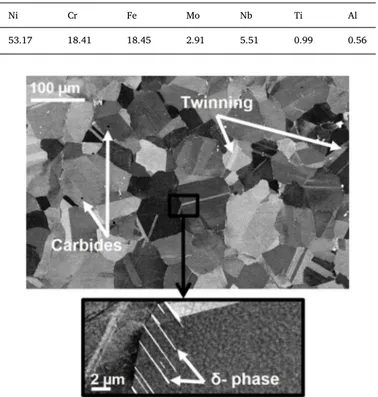
These properties are closely related to the chemical composition. In order to identify the composition of the work material Inconel 718, an energy dispersive spectroscopy (EDS) analysis has been carried out. Results are given inTable 2.
The metallurgical structure of Inconel 718 consists of several phases whose matrix is an austenitic solid solution“γ”. This matrix γ is har-dened by two phasesγ′ and γ″. Besides, the alloy is composed of δ-phase (Ni3Nb) in addition to the carbides particles (Fig. 1) that reveal abrasive
character while machining (Dosbaeva et al., 2010). 2.2. Experimental equipment
Machining experiments have been conducted using the conven-tional lubrication as well as two cryogenic cuttingfluids namely liquid nitrogen LN2and carbon dioxide LCO2. The experiments were carried
out using the same test configuration on a horizontal turning CNC lathe Danumeric 2. The conventional lubricant used during these experi-ments was the HOCUT 3380 supplied at a pressure of 20 bars, cooling the cutting zone. As for the LCO2system, it is composed of a bottle of
LCO2maintained at high pressure equal to 57 bars at room temperature
(liquid state). Concerning the LN2cryogenic trials, the cryogenic system
consists in a phase separator, the cryogenic control and the liquid
Table 1
Mechanical properties of Inconel 718.
Ultimate compression strength (MPa) 1754
Yield strength (MPa) 1150
Young modulus (GPa) 206
Hardness (HV100) 462
Density (g cm−3) 8.19
Thermal conductivity coefficient (W/m K) 11.2
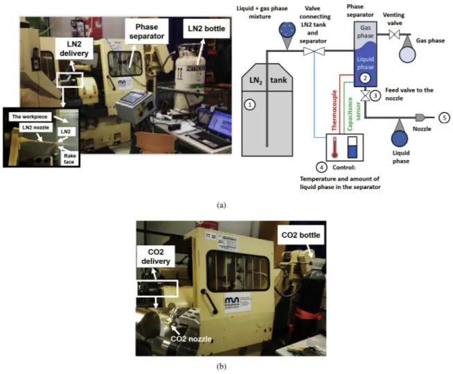
nitrogen bottle mounted on the CNC lathe (Fig. 2).
Indeed, the phase separator is employed in order to make sure that the phase of the nitrogen being delivered to the tip of the nozzle is liquid. The phase separator is placed upstream of the outlet of the tank to remove all vapour from the refrigerant. The separation is achieved physically due to density difference. This way, all the liquid phase is stored in the bottom part of the separator while the gas remains on the top part (Fig. 2a). In addition, the control of the phase of the nitrogen inside the separator is achieved with a thermocouple and a capacitance sensor which determines the amount of liquid inside the separator.
LN2spray was activated before starting the cutting process in order
to reach stable outlet condition. The parameters of the LN2flow are
depicted inTable 3.
The choice of these parameters has been established according to some previous works, in particularLequien (2017).Lequien (2017)has proved that the convective heat transfer coefficient is maximum when the pressure and the nozzle diameter of LN2delivery are high whereas
the distance projection and the inclination angle should be reduced. In this work, the LN2 parameters were not kept the same as Lequien
(2017). However, it was relevant to use bigger nozzle diameter, as lower as possible the distance projection and the inclination angle in order to optimize at best the liquidflow of the nitrogen.
2.3. Experimental methodology
Longitudinal turning experiments were conducted infinishing op-erations on Inconel 718 bar using the same cutting parameters and the same cutting tool asIturbe et al. (2016). In this study, these parameters werefixed whereas the LN2set-up has been changed.
Besides the cryogenic coolants (LN2 and LCO2), conventional
coolant has been employed as a reference in order to evaluate the cryogenic performance when machining Inconel 718. CVD coated car-bide inserts from Mitsubishi supplier (DNMG 150612-MS US905) were exploited in the trials.Table 4sets out the machining conditions.
The trials were carried out until achieving the target cutting time of
15 min or when the maximum tool flank wear defined as VBMAX= 0.3 mm was obtained. Each experiment has been performed
using a fresh cutting tool edge and has been repeated two times. Toolflank wear assessment was performed using a LEICA Z16 APO stereo-microscope. First of all, photos of the tool flank faces were captured (adding the scale). Then, one have to draw two parallel lines limiting the width of the maximum toolflank wear and hence VBMAX
was evaluated. Complementary observations of the cutting tools have been carried out using the scanning electron microscopy (SEM). In addition, profilometer measurements using the confocal profilometer, Alicona IFG4 device have been carried out in order to quantify the material loss volume of the tool as well as the adhered material volume. Machining forces were measured using Kistler 9121 dynamometer.
Onfinishing operations, the surface integrity of the machined part must respond to several quality requirements in terms of surface to-pography, surface hardness as well as residual stresses. For these rea-sons, during the experiments, surface roughness was measured in-situ after each cutting test using a Mitutoyo SJ-210 portable rugosimeter.
SEM observations of the machined part were carried out after two states of tool wear for each cooling condition: when performing with a new tool cutting edge and worn tool cutting edge. Electron backscatter diffraction (EBSD) technique was used in order to characterize the af-fected layer of the machined part. All the EBSD analysis were performed using a software called“Atex” (Beausir and Fundenberger, 2017).
Residual stress profiles of the machined surfaces were established using the incremental hole drilling method according to the ASTM standard by means of the RESTAN MTS300 hole-drilling equipment. 3. Results and discussions
3.1. Tool wear mechanisms
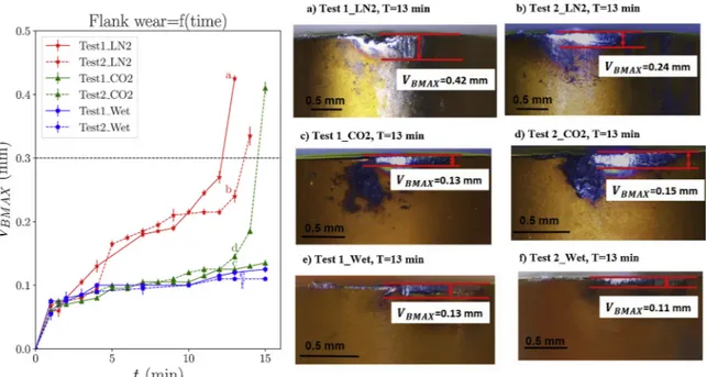
Toolflank wear evolution was measured throughout the turning operations for all cooling methods (conventional and cryogenic condi-tions). The trials were stopped when reaching 15 min of cutting in conventional lubrication even if the criterion of maximumflank wear namely VBMAX= 0.3 mm was not achieved. Regard the LCO2condition,
both tests were stopped at 15 min while the toolflank wear levels were notably different. However, under LN2cryogenic condition, the trials
were stopped when the criterion of VBMAXwas reached. Focusing on
Fig. 3, results indicated that the conventional condition revealed the longest tool life. In fact, the toolflank wear did not surpass 0.12 mm over 15 min of cutting in conventional lubrication. Both repetitions induced the same trend during the cutting process showing a good re-peatability.
As for the LCO2cooling strategy, a similar evolution has been
per-ceived up to 13 min of cutting. Nevertheless, beyond this duration, the toolflank wear progressed drastically to surpass the criterion at 15 min during the second repetition of LCO2experiment. With respect to LN2
cryogenic condition, toolflank wear increased rapidly from the first 2 and 6 min of cutting during test 1 and test 2 respectively causing re-duced tool life. In addition, toolflank wear progress in both cryogenic conditions is quite repeatable at the beginning of the machining pro-cess. Nevertheless, a significant variability was observed at 11 min and 13 min respectively in LN2and LCO2cooling strategies when the tool
flank wear increased notably. In conventional cooling approach, a homogeneous toolflank wear evolution was observed even after longer machining times. In contrast, during LN2cryogenic machining, wear
peaks occurred from the beginning of the turning process, indicating that the cutting process is not performed homogeneously while this parameter showed a steady and slow evolution in LCO2 cryogenic
condition except the last minutes of machining.
In this context,Fernandez et al. (2014)have demonstrated longer tool life obtained under LN2cryogenic condition when comparing with
theflood emulsion. The resulted difference between their work and the present work could be explained by the fact that the work material
Table 2
Chemical composition of Inconel 718 (% wt).
Ni Cr Fe Mo Nb Ti Al
53.17 18.41 18.45 2.91 5.51 0.99 0.56
Fig. 1. Illustration of Inconel 718 microstructure in the as-received state ob-served by SEM technique.
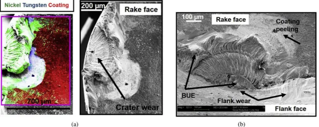
properties are significantly different compared to the one used in the current study. In addition, other factors could be identified consisting in the cutting conditions (cutting parameters as well as the cutting tool geometry). For these reasons, a scientifically rigorous comparison be-tween previous studies and the current job seems to be difficult. Ad-ditional analysis have been carried out in order to study the tool wear mechanisms when machining Inconel 718 under conventional lubrica-tion and cryogenic condilubrica-tions using SEM.Fig. 4shows the SEM ob-servations of the tool wear state on the rake face as well as theflank face obtained in wet condition after 15 min of cutting.
The main mechanism observed consists in adhesion wear. Effectively, deposits of workpiece material were stuck on the rake face near the cutting edge revealing the chip rubbing. This observation is proved by EDS analysis showing the adhered material consisted in nickel. In fact, as long as machining time increased, adhered layers were formed progressively to establish built-up edges that protect the rake face (Xue and Chen, 2011). However, when achieving stagnation state, the build-up edges are not stable inducing the peeling of tool coating material.
With respect to tool wear mechanisms under LCO2condition, the
two tests revealed different mechanisms. The first test exhibits the same trend as the conventional lubrication. Indeed, adhered layers are formed during machining as well as abrasion wear that is mainly caused by the hard carbide particles present in the workpiece material. It is worth mentioning that these two wear mechanisms are closely related (Cantero et al., 2013). Effectively, the adherence of the workpiece material inducing the formation of the built-up edge (BUE) leads to tool chipping, because of the instability of BUE that breaks off alternatively tearing out a small lump of the cutting edge (Fig. 5).
Fig. 2. Experimental set-up for the cryogenic tests: (a) LN2set-up; (b) LCO2set-up.
Table 3
LN2and LCO2flow parameters.
LN2 LCO2
The diameter of the nozzle (mm) 1.5 0.4
The pressure (bar) 10 57
Projection angle (∘) 15 45
Delivery position Rake face Rake face
Table 4
Working conditions.
Workpiece Geometry Cylindrical bar Material Inconel 718
Cutting parameters Cutting speed (m/min) 70 Feed (mm/rev) 0.2 Depth of cut (mm) 0.2
Tool Tool insert Coated carbide
Cutting edge angle (∘) 93 Rake angle (∘) 9 Relief angle (∘) 6 Nose radius (mm) 1.2
Coolants Conventional Hotcut
Cryogenic LN2
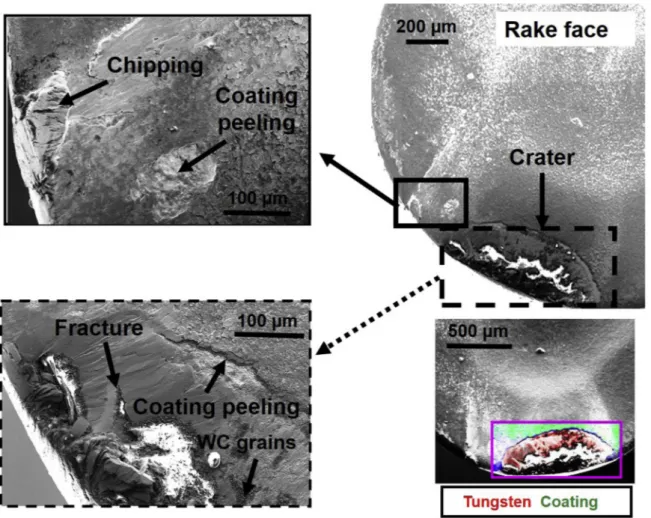
Nevertheless, the tool wear modes and mechanisms occurred during the second test when using LCO2are rather different. Besides the flank
wear, drastic crater wear took place caused by the plucking out of the tool coating particles as illustrated inFig. 6.
Micro-cracks and chipping of the cutting edge have also been ob-served. Overall, these mechanisms are induced by mechanical loads which developed chipping, fracture and coating peeling as well as the chemical interactions at the tool-workpiece and tool-chip interfaces that caused adhesion (Halim et al., 2019).
Concerning the LN2cooling conditions, tool wear mechanisms that
have been detected through the SEM observations and the EDS analysis are not far from those obtained during the second test of LCO2
lu-brication. Indeed, during both LN2tests, the degradation of cutting tool
is primarily caused by adhesion and micro-chipping as depicted in
Figs. 7 and 8.
In particular, welded chips on the rake face have been observed indicating the non-efficient performance of the LN2 to evacuate
properly the chips. It may also be concluded that high temperature obtained during machining contributing to welding the chips reveals that the LN2cutting fluid did not cool significantly the tool-chip
in-terface (Liao et al., 2008). Furthermore, due to higher wear of the cutting tool, the friction and the temperature increase at the cutting area leading to serious damage to the tool (Wagner et al., 2015) and thereby rapid wear and reduced tool life (Liang and Liu, 2018).
Another aspect should be stated consisting in that when delivering LN2cuttingfluid on the tool rake face, it seems complicated to avoid
cooling the unmachined workpiece. Consequently, the work material deformation behavior as well as the thermal properties could change by the cryogenic temperature (−196∘C). Thereby, the cutting process in
this case turns out to be nonhomogeneous affecting the tool wear re-sistance. Moreover, when examining the chip morphology obtained under all cooling conditions, there is no significant difference; the chips exhibit almost the same morphology as depicted inFig. 9.
Fig. 3. Toolflank wear evolution under wet, LN2and LCO2cooling conditions during the tests.
3.2. Cutting forces
Assessing the cutting forces is fundamental to control the power consumption during the cutting process as well as to estimate the dif-ficulty of a material to be cut. In fact, the cutting forces are closely related to the cutting conditions such as the material properties of the workpiece, the cutting tool (the geometry, the material, the coating, etc.), the cutting parameters in addition to lubrication approaches. In this study, one is interested to point out the machining forces evolution when cutting Inconel 718 under several cooling strategies namely conventional lubrication and cryogenic conditions using LN2and LCO2.
Three components have been evaluated during the turning operations: the cutting forces (Fc), the feed forces (Ff) and the passive forces (Fp).
Results showed that all cutting forces components exhibit lower values in conventional cooling condition than in the case of cryogenic conditions (Fig. 10). Indeed, the cryogenic cutting fluids (LN2 and
LCO2) display very low temperature throughout machining time
leading to increase theflow stress of the workpiece material. As a result, the machining forces components heighten significantly. For instance, when examining the values of the cutting forces components found in conventional and cryogenic conditions, a strong difference is obtained where the maximum value of cutting forces that has been measured in conventional condition is 180 N. In contrast, in LN2and LCO2cooling
approaches, this variable has exceeded 300 N and 250 N respectively at the end of cutting. Furthermore, the feed forces show the same ten-dency where the highest values are achieved in LN2cryogenic
condi-tions. However, the passive forces revealed the highest values recorded in all cooling environment compared to the cutting and feed forces reaching over 1200 N after 14 min of machining in LN2condition.
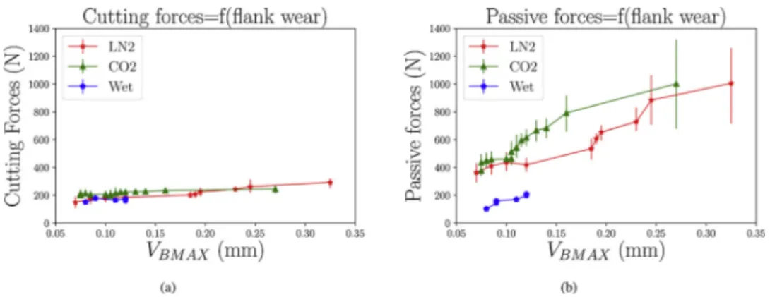
Cutting forces values are key factors to indicate the tool wear state.
Fig. 10illustrates the cutting forces measurements at the beginning and the end of the cutting process revealing the effect of tool wear evolu-tion. Obviously, over machining time, the tool wear increases relatively to the cooling environment and therefore cutting forces rise as well. In
addition, when comparing between the three components of the cutting forces regardless the lubrication strategy, one could recognize that the passive force measurements showed the highest values, mostly by the end of the machining process where the toolflank wear increased no-tably (Grzesik et al., 2018). In addition, when comparing between the different cooling methods, one could notice that passive force progress is slow and steady in conventional condition. Nevertheless, under cryogenic conditions, this parameter evolves drastically at the end of machining. This tendency is more pronounced under LN2 cryogenic
condition than under LCO2condition. This result may be attributed to
the rapid toolflank wear progress in LN2cryogenic strategy mentioning
that the passive forces are the most sensitive to toolflank wear as de-picted inFig. 11.
In this context,Arrazola et al. (2014)obtained similar trend when comparing the progress of cutting forces components using unworn and worn tools. They highlighted that passive forces evolution was the most sensitive to tool wear depending on tool geometry as well as the cutting parameters employed.
3.3. Surface integrity 3.3.1. Surface roughness
Surfacefinish is a crucial parameter that provides good machining performance of machined parts. Fig. 12 illustrates the evolution of surface roughness obtained in conventional and cryogenic conditions. Results showed that conventional coolant tended to enhance sig-nificantly the surface finish as it provides the lowest values in terms of the average roughness Raas well as the total height of the profile Rt.
Concerning the LCO2 condition, it induced approximately the same
tendency as the conventional strategy. Nevertheless, in LN2cryogenic
condition, the surface quality exhibited a mediocre state in comparison with wet and LCO2 conditions. Actually, under LN2cryogenic
condi-tion, surface roughness has achieved very high values reaching more than 3μm of Raand 20μm of Rt. In comparison with LN2cryogenic Fig. 5. SEM observations of the tool wear after 15 min of machining in LCO2condition during Test 1: (a) rake face/EDS analysis; (b)flank face.
condition, conventional lubrication produces an improvement of more than 30%.
This denotes that the cooling and lubrication choice affects drasti-cally the expected results with regard to the surface roughness re-quirements established by industrial manufacturing.
Furthermore, as displayed inFig. 12, the measurements of the sur-face roughness are not recorded till the end of the cutting process in the case of LN2cooling strategy due to the limitations of the equipment as
the surfacefinish was too rough. For this reason, one has resorted to use
the profilometer in order to characterize the LN2surfacefinish
mea-suring the average areal roughness Sa.Fig. 13highlights the increase of
Sameasured at different machining times. Indeed, the scanned surfaces
reveal the presence of adhered particles on the machined workpiece surfaces that become more important as the machining time increases. This could be the main reason of the worst surface quality obtained in LN2cryogenic condition.
Results showed that the average areal roughness Savalues are in the
range of 1.18μm when the microchips are not present. In contrast, the
Fig. 6. SEM observations of the tool wear after 15 min of machining in LCO2condition during Test 2.
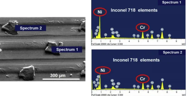
machined surfaces exhibiting the adhered microchips revealed higher values holding 2.13 and 2.67μm. Overall, whatever the rate of the adhered microchips, the surfacefinish revealed in this case is poor. To better understand the poor surface quality when machining Inconel 718 under LN2cryogenic condition, SEM metallographic observations of the
machined surface have been carried out.Fig. 14describes the machined surface obtained after 11 min of cutting under LN2cryogenic cooling
condition. The major defects observed consist essentially in the adhered material as well as the smearing.
Additionally, EDS analysis have been carried out on the adhered material showing that the chemical composition of these particles ex-hibited the same elements composing the Inconel 718 alloy (Fig. 15).
These observations of the machined surface could be explained by the fact that during the chip formation process, the LN2cuttingfluid did
not efficiently evacuate the chip from the cutting zone. Consequently, the chips were stuffed between the cutting edge and the freshly ma-chined surface. Furthermore, the degree of tool wear affects strongly the machined surface quality knowing that thereby the cutting forces and the cutting temperature increase as well when the tool wear evolves. Indeed, these features have been observed in previous work (Zhou et al., 2012). The study pointed out that the chip debris (the adhered chip) is attributed to the increase of the plastic deformation localized at the cutting tool-work material interface. It is worth men-tioning that the carbides particles could deteriorate the machined sur-face quality by generating the smearing of the fresh machined sursur-face as displayed inFig. 14.
Another correlation could be established with respect to the sig-nificant build-up edges that have been observed specifically in the case of LN2cooling conditions (Section 3.1) and the adhered microchips.
Indeed, BUE are not stable during the cutting process (Ahmed et al., 2017). In contrast, there are regularly either detached or welded on the
freshly machined surface leading to higher surface roughness as de-scribed previously.
3.3.2. Microstructure damage
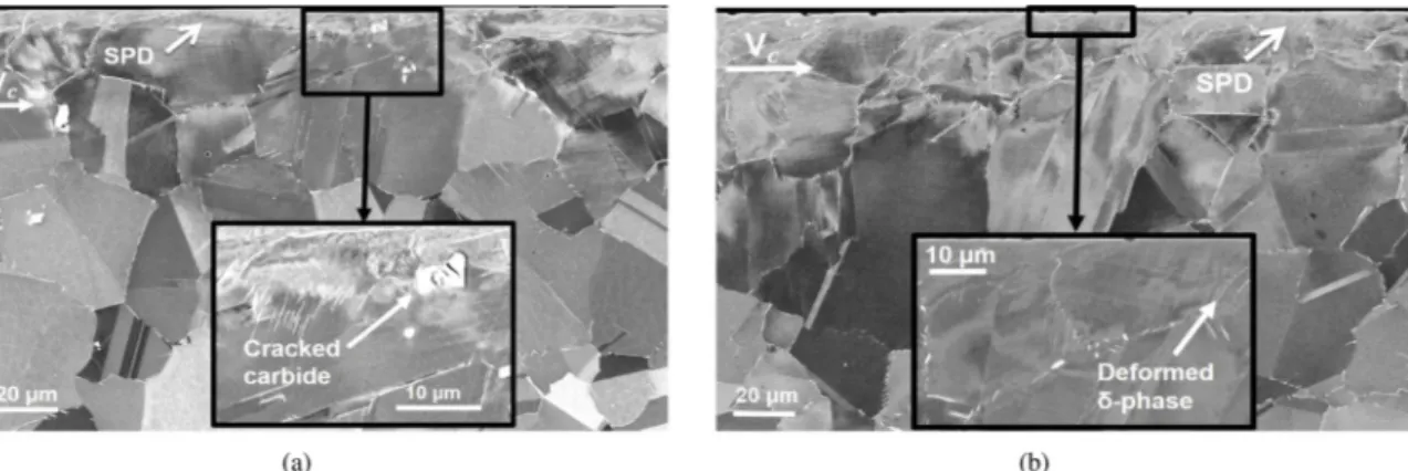
Metallurgical alterations take place during the machining process. Indeed, authors have divided the machined workpiece material globally into two main regions (bulk material and affected zone) induced mainly by the combination of three origins namely the mechanical, thermal as well as chemical effects. The most common defects occurring after machining Inconel 718 on the surface and subsurface consist mainly in deformed grains along the cutting direction (Zhou et al., 2012), cracked carbide particles and surface cavities as reported in literature (M’Saoubi
et al., 2012).
Figs. 16–18disclose the machined surfaces and subsurfaces altera-tions induced by machining under the conventional and cryogenic conditions when using new and worn tools along the cutting direction. First of all, when focusing on the SEM metallographic observations of the machined surfaces obtained when cutting with new tools, all the cooling strategies have exhibited similar effect generating very thin affected zone. Indeed, very close to the free machined surface, a severe plastic deformation (SPD) could be observed in all cooling conditions.
M’Saoubi et al. (2014)pointed out that very close to the free machined surface severe plastic deformation occurs when machining Inconel 718. SEM observations obtained when machining employing semi-worn and worn tools highlight remarkable difference between surface da-mage induced when using new and several state of tool wear. As dis-played in the previousfigures, an appearance of deeper affected layer is clearly observed compared to the case of fresh tool. For instance, very close to the machined surfaces, more deformed grains are observed indicating a particular orientation along the cutting direction as re-ported inSharman et al. (2015).Chen et al. (2016)extensively focused
Fig. 8. SEM observations of the tool wear after 14 min of machining in LN2condition during Test 2: (a) rake face/EDS analysis; (b)flank face.
on the surface integrity after broaching process of Inconel 718, espe-cially the microstructural damage localized in the subsurface layer. They claimed that at this zone the grains are highly plastically de-formed causing cracked carbides.
Similarly, when examining the SEM observations, one could define three regions that compose the work material. Thefirst region consists in a non-modified microstructure known as the bulk material. Secondly, a deformed zone reveals the elongation of the grains along the cutting direction due to the intense plastic deformation occurring during the cutting process. The third region is located at the vicinity of the free machined surface indicating a severe plastic deformation much higher than the one obtained in the previous zone where the grains undergo a drastic deformation.
Depending on the cooling conditions that induce miscellaneous tool wear state, the depth of each region is relatively variable. For instance, similar trend was revealed under conventional and LCO2conditions. In
fact, both cooling conditions have generated approximately the same tool wear level and thereby inducing almost identical effect on the deformed subsurface. By contrast, as long as the tool wear increases, the damage of the machined affected layer is more pronounced as illu-strated by the case of LN2strategy where the toolflank wear have
ex-ceeded the criterion. These observations are in agreement withZhou et al. (2011)that have pointed out the tool wear effect on subsurface deformation of nickel based alloy mentioning that tool wear as well as high cutting forces are the major factors considered for plastic de-formation occurred beneath the machined surface.
However, it is important to affirm that accurately characterizing the depth of the affected zone turns out to be difficult through the SEM observations. That's why, EBSD analysis will be discussed in the next paragraphs in order to estimate the depth of the affected layer.
The EBSD technique is a complementary characterization to SEM technique for investigating the local plastic deformation produced fol-lowing the machining process. Machining using new tools regardless the cooling strategy induces similar effect. That's why, in this paper, one is content with identifying the effect of tool wear in the case of LCO2
cooling strategy and subsequently comparing between the three cooling methods when the tool wear evolved.
Fig. 19gives information about the misorientation gradients mea-sured inside the deformed grains chosen in the region close to the machined surface in the case of LCO2cooling strategy when using new
and semi-worn tools.
Accordingly, the regions subjected to large deformation are those that have undergone large grain elongation. Indeed, as long as the depth beneath the surface increases, the misorientation gradients inside the grains decrease. Obviously, when the grains are located very close to the machined surface, the plastic deformation at this position ex-hibits the highest values revealing a severe misorientation gradients (either using the cumulative or point to point method) (Azarbarmas et al., 2016; Mandal et al., 2010). For instance, the cumulative orientations developed along the L1 and F1 lines exhibit higher mis-orientation gradient within the deformed grains. It is apparent from
Fig. 19that the cumulative misorientation continuously increases to almost 60∘(at a distance of 25μm).
In contrast, as for the grains located far away from the machined surface, the misorientation gradient inside the grains reduces sig-nificantly because of the decrease of the plastic deformation for in-stance along the lines I1 and J1. However, when focusing on these two lines, slight difference could be noticed concerning the misorientation gradients values. Although these two lines are located almost at the same depth from the machined surface, each grain was initially or-iented differently and thereby the rate of plastic deformation may not be the same. In addition, an important aspect should be identified concerning the non-indexed zone that proves the severe plastic de-formation occurring very close to the free machined surface.
Moreover, when focusing on the tool wear effect and thereby comparing between the profiles obtained using new and semi-worn tools, one could notice that the highest misorientation gradients inside the deformed grains is attributed to the case that reveals higher tool wear. As the tool wear increases, the cutting forces tend to increase notably and therefore plastic deformation increases as well (Pradhan
Fig. 10. Comparison between cutting forces components: at the beginning (a); at the end (b) of test.
et al., 2017). In particular, it could be observed that the orientation gradient measured along A1 and F1 inside two deformed grains loca-lized at the vicinity of the two cutting free surfaces (Fig. 19) generated using respectively new and semi-worn tools exhibit pronounced dif-ference with respect to the cumulative misorientation plots where larger values are detected in the case of employing semi-worn tool.
In addition, when examining the resulting profiles as displayed in
Figs. 19 and 20, the latter's show clearly the higher values of the cu-mulative misorientation inside the deformed grains localized at the vicinity of the machined free surfaces when using semi-worn tools as well as worn tool respectively revealed under wet, LCO2 and LN2
cooling approaches.
Indeed, this confirms the intense grain rotation and plastic activity in this region induced by the cutting process.Zhou et al. (2011)have
pointed out the tool wear effect on the surface integrity, in particular the depth of the plastically deformed layer. They related the deforma-tion depth with the different tool condideforma-tions (new, semi-worn tool and worn tool) and the resultant cutting forces. The resultsfigured out that the damage of the subsurface layer during the machining process is mainly governed by the tool wear levels during chip formation. In other words, the tool wear levels have major impact on the subsurface de-formation depth as well as microstructure change. In fact, this could be attributed to the parallel progress of the thermal and mechanical loads acting on the machined surface resulting from the tool wear evolution. Effectively, in the case of LN2cryogenic condition that exhibited the
highest tool wear value (VBMAX= 0.35 mm), other aspect could be
ea-sily identified consisting in a thin layer observed in the immediate subsurface of the workpiece that was partially indexed. This is closely
Fig. 12. Surface roughness evolution under wet, LN2and LCO2cooling conditions: (a) average roughness, (b) total height of the profile.
Fig. 13. Surface topography scanned using the Bruker profilometer after machining under LN2condition: (a) t = 0.5 min, (b) t = 5.5 min, (c) t = 11 min.
related to the heavy plastic deformation occurred at this region indu-cing distortion of the grains and thereby difficulties to accurately index. 3.3.3. Residual stresses
Residual stresses induced by machining affect strongly the products functional performances for instance the fatigue life (Javidi et al., 2008) as well as the resistance to stress corrosion cracking (Soyama and Takakuwa, 2015). In this study, one is interested to point out the in-fluence of conventional and cryogenic conditions on the residual stress profiles beneath the machined surface when cutting using fresh tools. In addition, this work aims tofigure out the effect of tool wear state on residual stress profiles obtained under all cooling conditions.
As depicted in Fig. 21, regardless the cooling conditions, tensile residual stresses are dominant near the surface indicating that the thermal effect prevails against the mechanical effect along the cutting direction. Actually, one may assert that near the surface, the tensile residual stresses are mainly associated to the thermal load effect. However, the compressive residual stresses beneath the machined sur-face are induced by the increase of the mechanical load and the plastic deformationflow (Pawade et al., 2008).
Nevertheless, when examining all the cooling strategies, the mag-nitudes of the tensile residual stress in the hoop direction were sig-nificantly lower under cryogenic conditions compared to conventional lubrication. Obviously, tensile hoop stresses dropped from 483 MPa in
wet condition to 180 and 102 MPa respectively under LCO2and LN2
cooling conditions indicating the efficiency of the cryogenic cutting fluids. On the other hand, since the thermal conductivity of the work material is poor and the cooling capacity of the conventional lubrica-tion is limited compared to cryogenic temperature, all these factors result in the domination of the thermal effect especially very close to the machined surface in conventional condition.
Additionally, conventional condition generated the largest tensile hoop stress layer reaching 100μm below the machined surface and induced a compressive peak holding around -200 MPa. In contrast, LCO2 cooling condition revealed the largest compressive depth
in-itiating from 35μm to more than 400 μm and provided the highest compressive peak reaching almost −300 MPa. Concerning the LN2
condition, beneath the machined surface within 30μm, hoop stress shifted to compressive values showing larger compressive depth com-pared to conventional condition. Overall, under cryogenic conditions, as the depth beneath the workpiece surface rose, the tensile hoop stresses rapidly dropped and quickly reached compressive levels before slowly returning to bulk values in the case of machining using new tools.
As for the axial stress profiles, results indicated very low tensile values near the surface that shifted gradually to compressive trend under wet and LN2cryogenic conditions. However, under LCO2
cryo-genic condition, residual stress in the feed direction induced more
Fig. 15. EDS analysis carried out on the machined surface after 11 min of machining under LN2condition.
Fig. 16. SEM observations of the machined surfaces in wet condition using new and semi-worn tools: (a) new tool, (b) semi-worn tool (VBMAX= 0.12 mm, t = 15 min).
compressive values from the depth of 50μm.
When examining the cutting forces values obtained under all cooling conditions using a new tool, both cryogenic approaches re-vealed the highest values for all cutting forces components (especially the passive forces) showing the dominance of mechanical loading compared to conventional lubrication. This could likely justify the lower tensile residual stresses recorded near the surface and the higher compressive depth obtained under both cryogenic conditions.
It should also be noticed that the measured stress trends are dif-ferent in axial and hoop directions, confirming that both mechanical and thermal effects contribute to the final residual stress state in a complex way that cannot be easily explained. Probably, the anisotropy obtained when comparing both components with respect to hoop and axial stresses could be explained by the fact that cutting direction un-dergoes a significant impact of the cutting speed and depth of cut as affirmed byZhou et al. (2014). Nevertheless, along the feed direction, lower tensile residual stresses were recorded as displayed inFig. 21. The same observation wasfigured out inPusavec et al. (2011)where tensile residual stresses tended to be more important in the cutting direction than in the feed direction.
Focusing onFig. 22, as the tool wear increased in all cooling con-ditions, the residual stresses near the machined surface shifted to higher tensile stress range along the cutting direction and the compressive stress state beneath the machined surface increased drastically in both directions (axial and hoop) compared to the results obtained when machining with new tools. For instance, when examining the residual stress profiles generated in conventional lubrication, near the machined surface, the tensile residual stress evolved to achieve around 668 MPa and 214 MPa respectively in the cutting and feed directions while these components revealed lower values in the case of machining using new tools.
Besides, residual stresses generated along the cutting direction
dropped rapidly to compressive values within 40μm indicating a compressive peak holding around −408 MPa and then leveling out from 375μm below the workpiece surface. By contrast, the axial re-sidual stress shifted to compressive value at 34μm below the surface inducing higher compressive peak holding around−427 MPa.
With regard to the LCO2cooling condition, as expected, near the
surface, hoop residual stresses rose significantly reaching 405 MPa and then decreased gradually to compressive values at the depth of 50μm showing higher compressive peak around −468 MPa in comparison with the values obtained in the case of using new tool. Alternatively, along the axial direction, residual stresses tended to be much more compressive from the first increment (10 μm) and penetrated to a deeper depth inducing greater compressive peak holding−746 MPa compared to the result obtained when cutting with a new tool. Another aspect that should be noticed is that when comparing conventional and LCO2cooling conditions that exhibited the same tool wear state, results
showed better residual stress distribution revealed in the case of LCO2
strategy indicating the advantage of cryogenic approaches with respect to fatigue resistance.
Concerning the LN2cooling method, when examining the residual
stress distribution near the surface, in the cutting direction, it is obvious that residual stresses were tensile. Nevertheless, they are surprisingly maintained almost at the same range when using a new tool holding 189 MPa versus 102 MPa respectively. Consequently, one is interested to mention that when machining with severe tool wear, it is well known that temperatures rise drastically near the surface due to the increase of friction contact area between tool flank face and the workpiece. However, LN2cryogenic condition that reveals the highest tool wear
level induces lower tensile residual stresses along the cutting direction compared to conventional and LCO2cooling conditions. In the other
hand, along the feed direction, very close to the surface, stresses are much more compressive shifting from 113 MPa to−855 MPa when the
Fig. 17. SEM observations of the machined surfaces in LCO2condition using new and semi-worn tools: (a) new tool, (b) semi-worn tool (VBMAX= 0.14 mm, t = 15 min).
tool wear has evolved dramatically. In addition, the maximum com-pressive value indicates much higher value than the yield stress about −1415 MPa due to severe hardening. In this context, Peng-Lin et al. (2013)reported that the maximum compressive residual stress and its depth penetration rise drastically when worn tools are used due to es-sentially the significant growth of cutting forces. Indeed, as it was mentioned in Section3.2, machining forces evolved dramatically when tool wear has increased, especially the passive forces. Thereby, the residual stresses developed in the workpiece after machining are strongly affected by the increase in cutting forces.
Moreover, when comparing residual stress profiles along the feed direction in all cooling conditions, LN2 cryogenic condition leads to
higher compressive value from the machined surface in which the tool wear was the most pronounced. Indeed,Sharman et al. (2006) have figured out that worn tools affects drastically the axial residual stresses values when machining with square tool and cutting speed about 120 m/min as well as hexagonal shape of the tool with a cutting speed of 40 m/min produced compressive values on the surface that rapidly dropped to more compressive trend at the depth of the affected zone. This result could be explained by the notable increase of the passive forces as the cutting tools were worn.
As it can be seen inFig. 22, concerning both cryogenic profiles, it is
worth mentioning that the depth of the thermally stressed layer is much thinner than the depth of the machined layer affected by mechanical loads compared to those obtained under conventional lubrication. In other words, cryogenic cutting fluids not only ensure efficient con-tribution to reducing the thermal effect on residual stress fields, but also provides increasing the compressive residual stress range (higher pas-sive forces components). However, it should be noticed that generating compressive residual stresses in thefinished product and increasing the passive forces during machining (power consumption) constitute a di-lemma and hence a compromise is required.
4. Conclusion
In this work, a comparative study has been conducted in order to investigate the cryogenic performance using the liquid nitrogen LN2
and the carbon dioxide LCO2when machining Inconel 718 infinish
turning operations. The following conclusions are identified based on the experimental results and the tested conditions of the present re-search:
Fig. 19. EBSD maps of the machined surfaces (projection axis [001]) obtained in LCO2condition using new tool (a) and semi-worn tool (b); misorientation gradients measured inside deformed grains (in the direction as indicated by lines) in the case of: (c) new tool, (d) semi-worn tool.
•
With respect to tool life, traditional lubrication produced the longest tool life. Concerning the LCO2condition, it exhibited similarten-dency compared to the wet condition until reaching 14 min of cut-ting. However, LN2cryogenic condition revealed the shortest tool
life. Besides, in this condition, welded chips on the rake face have been discerned.
•
Cutting forces indicated higher values under both cryogenic condi-tions compared to conventional lubrication revealing that theflowof the work material increased due to cryogenic temperature. Additionally, it was noticed that the passive forces are the most sensitive component to toolflank wear rise.
•
As for the surface roughness, this parameter indicated analogous trend under conventional and LCO2 cooling methods presentinglower value compared to LN2strategy. In addition, the latter
gen-erated the largest values of surface roughness due to the adhered chips that have been observed.
Fig. 20. EBSD maps of the machined surfaces (projection axis [001]) obtained in wet condition using a semi-worn tool (a) and in LN2condition using worn tool (b); misorientation gradients measured inside deformed grains in the case of: (c) wet, semi-worn tool, (d) LN2, worn tool.
Fig. 21. Residual stress profiles near and beneath the machined surface using a new tool wet, LCO2and LN2cooling conditions measured along: (a) hoop direction (cutting direction); (b) axial direction (feed direction).
•
In the matter of residual stress, results pointed out that when cutting using new tools, conventional lubrication produced the highest tensile value near the surface along the cutting direction and in-duced the lowest compressive peak and the lowest compressive depth. In both cryogenic conditions, near the surface, the hoop re-sidual stresses exhibited almost similar values. By contrast, LCO2condition produced the highest maximum compressive value as well as the largest compressive depth when cutting with new tools.
•
Residual stress profiles obtained when machining using semi-worn tools and worn tool respectively in conventional, LCO2 and LN2cooling approaches, showed that both cryogenic conditionsfigured out the best performances obtained compared to wet condition. Furthermore, when cutting employing worn tool, much more com-pressive values have been recorded, especially along the axial di-rection.
•
Regard the affected layer of the workpiece, when using new tool, no significant difference have been observed under all cooling strate-gies. By contrast, LN2 cryogenic condition induced the mostim-portant damage when machining using worn tool.
•
If comparing the tested cooling conditions, LCO2cooling strategy isthe most appropriate since it is able to withstand 15 min with ac-ceptable tool wear and produces a better surface integrity than conventional and LN2conditions.
Author contributions
S. Chaabani: Conceptualization, methodology, writing – original draft, investigation. P.J. Arrazola: Conceptualization, supervision, va-lidation, resources, review & editing, project administration. Y. Ayed: Conceptualization, supervision, formal analysis, review & editing, conceptualization. A. Madariaga: Methodology, formal analysis, review & editing. A. Tidu: Methodology, resources, review & editing. G. Germain: Conceptualization, supervision, validation, resources, review & editing, project administration.
Conflict of interest
The authors declare that there is no conflict of interest. Acknowledgments
The authors would like to thank the Basque Government and Spanish Government for the financial support provided to the PROCODA (KK-2019/00004) and CRYOMACH (EXP-00116898/INNO-20182049) projects respectively. This work was also supported by the French Institute Carnot ARTS.
References
Ahmed, Y., Fox-Rabinovich, G., Paiva, J.M., Wagg, T., Veldhuis, S.C., 2017. Effect of built-up edge formation during stable state of wear in AISI 304 stainless steel on machining performance and surface integrity of the machined part. Materials 10, 1230.
Arrazola, P., Garay, A., Fernandez, E., Ostolaza, K., 2014. Correlation between toolflank wear, force signals and surface integrity when turning bars of Inconel 718 infinishing conditions. Int. J. Mach. Mach. Mater. 15, 84–100.
Ayed, Y., Germain, G., Melsio, A.P., Kowalewski, P., Locufier, D., 2017. Impact of supply conditions of liquid nitrogen on tool wear and surface integrity when machining the Ti-6Al-4V titanium alloy. Int. J. Adv. Manuf. Technol. 93, 1199–1206.
Azarbarmas, M., Aghaie-Khafri, M., Cabrera, J., Calvo, J., 2016. Dynamic recrystallization mechanisms and twining evolution during hot deformation of Inconel 718. Mater. Sci. Eng. A 678, 137–152.
Bagherzadeh, A., Budak, E., 2018. Investigation of machinability in turning of difficult-to-cut materials using a new cryogenic cooling approach. Tribol. Int. 119, 510–520. Beausir, B., Fundenberger, J.J., 2017. Analysis Tools for Electron and X-ray Diffraction,
ATEX-Software. Université de Lorraine-Metz. http://www.atex-software.eu.
Behera, B.C., Alemayehu, H., Ghosh, S., Rao, P.V., 2017. A comparative study of recent lubri-coolant strategies for turning of Ni-based superalloy. J. Manuf. Process. 30, 541–552.
Bordin, A., Sartori, S., Bruschi, S., Ghiotti, A., 2017. Experimental investigation on the feasibility of dry and cryogenic machining as sustainable strategies when turning Ti6Al4V produced by additive manufacturing. J. Clean. Prod. 142, 4142–4151.
Cantero, J., Díaz-Álvarez, J., Miguélez, M., Marín, N., 2013. Analysis of tool wear patterns infinishing turning of Inconel 718. Wear 297, 885–894.
Chen, Z., Peng, R.L., Moverare, J., Avdovic, P., Zhou, J.M., Johansson, S., 2016. Surface integrity and structural stability of broached Inconel 718 at high temperatures. Metall. Mater. Trans. A 47, 3664–3676.
Devillez, A., Coz, G.L., Dominiak, S., Dudzinski, D., 2011. Dry machining of Inconel 718, workpiece surface integrity. J. Mater. Process. Technol. 211, 1590–1598.
Dosbaeva, G.K., Veldhuis, S.C., Elfizy, A., Fox-Rabinovich, G., Wagg, T., 2010. Microscopic observations on the origin of defects during machining of direct aged (DA) Inconel 718 superalloy. J. Mater. Eng. Perform. 19, 1193–1198.
Ezugwu, E., Wang, Z., Machado, A., 1999. The machinability of nickel-based alloys: a review. J. Mater. Process. Technol. 86, 1–16.
Fernandez, D., Navas, V., Sandá, A., Bengoetxea, I., 2014. Comparison of machining Inconel 718 with conventional and sustainable coolant. MM Sci. J. 514, 506–510.
Grzesik, W., Niesłony, P., Habrat, W., Sieniawski, J., Laskowski, P., 2018. Investigation of tool wear in the turning of Inconel 718 superalloy in terms of process performance and productivity enhancement. Tribol. Int. 118, 337–346.
Halim, N., Haron, C., Ghani, J., Azhar, M., 2019. Tool wear and chip morphology in high-speed milling of hardened Inconel 718 under dry and cryogenic CO2conditions. Wear
426–427, 1683–1690.
He, Z., Zhang, X., Ding, H., 2016. Comparison of residual stresses in cryogenic and dry machining of Inconel 718. Procedia CIRP 46, 19–22.
Herbert, C., Axinte, D., Hardy, M., Brown, P., 2012. Investigation into the characteristics of white layers produced in a nickel-based superalloy from drilling operations. Mach. Sci. Technol. 16, 40–52.
Hong, S.Y., Markus, I., Jeong, W., 2001. New cooling approach and tool life improvement in cryogenic machining of titanium alloy Ti-6Al-4V. Int. J. Mach. Tools Manuf. 41, 2245–2260.
Hongbo, D., Gaochao, W., 2015. Effect of deformation process on superplasticity of Inconel 718 alloy. Rare Met. Mater. Eng. 44, 298–302.
Iturbe, A., Hormaetxe, E., Garay, A., Arrazola, P.J., 2016. Surface integrity analysis when machining Inconel 718 with conventional and cryogenic cooling. Procedia CIRP 45, 67–70.
Javidi, A., Rieger, U., Eichlseder, W., 2008. The effect of machining on the surface in-tegrity and fatigue life. Int. J. Fatigue 30, 2050–2055.
Jawahir, I., Zhengwen, P., Yang, S., Giovanna, R., Yusuf, K., Tao, L., Domenico, O.W., 2012. Cryogenic processing of materials for enhanced product life, performance and sustainability. In: 15th International Conference on Advances in Materials and
Fig. 22. Residual stresses profiles near and beneath the surface machined using semi-worn tools under conventional and LCO2cooling conditions and worn tool under LN2condition measured along: (a) hoop direction; (b) axial direction.
Processing Technology. Australia.
Kaynak, Y., 2014. Evaluation of machining performance in cryogenic machining of Inconel 718 and comparison with dry and MQL machining. Int. J. Adv. Manuf. Technol. 72, 919–933.
Kumar, S., Satapathy, B., Pradhan, D., Mahobia, G.S., 2019. Effect of surface modification on the hot corrosion resistance of Inconel 718 at 700∘C. Mater. Res. Express 6, 086549.
Lequien, P., 2017. Etude fondamentale de l’assistance cryogénique pour application au fraisage du Ti6Al4V (Ph.D. thesis). Thése de doctorat dirigée par Poulachon, GérardOuteiro, José Carlos et Rech, Joël Génie mécanique - procédés de fabrication Paris, ENSAM 2017.
Liang, X., Liu, Z., 2018. Tool wear behaviors and corresponding machined surface to-pography during high-speed machining of Ti-6Al-4V withfine grain tools. Tribol. Int. 121, 321–332.
Liao, Y., Lin, H., Wang, J., 2008. Behaviors of end milling Inconel 718 superalloy by cemented carbide tools. J. Mater. Process. Technol. 201, 460–465.
Mandal, S., Bhaduri, A., Vadlamani, S.S., 2010. A study on microstructural evolution and dynamic recrystallization during isothermal deformation of a Ti-modified austenitic stainless steel. Metall. Mater. Trans. A: Phys. Metall. Mater. Sci. 42, 1062–1072.
Mehta, A., Hemakumar, S., Patil, A., Khandke, S., Kuppan, P., Oyyaravelu, R., Balan, A., 2018. Influence of sustainable cutting environments on cutting forces, surface roughness and tool wear in turning of Inconel 718. Mater. Today: Proc. 5, 6746–6754.
M’Saoubi, R., Axinte, D., Herbert, C., Hardy, M., Salmon, P., 2014. Surface integrity of nickel-based alloys subjected to severe plastic deformation by abusive drilling. CIRP Ann. 63, 61–64.
M’Saoubi, R., Larsson, T., Outeiro, J., Guo, Y., Suslov, S., Saldana, C., Chandrasekar, S., 2012. Surface integrity analysis of machined Inconel 718 over multiple length scales. CIRP Ann. 61, 99–102.
Pawade, R., Joshi, S.S., Brahmankar, P., 2008. Effect of machining parameters and cutting edge geometry on surface integrity of high speed turned Inconel 718. Int. J. Mach. Tools Manuf. 48, 15–28.
Peng-Lin, R., Zhou, J., Johansson, S., Billenius, A., Bushlya, V., Ståhl, J., 2013. Surface integrity and the influence of tool wear in high speed machining of Inconel 718. The 13th International Conference on Fracture (ICF13).
Pereira, W.H., Delijaicov, S., 2019. Surface integrity of Inconel 718 turned under cryo-genic conditions at high cutting speeds. Int. J. Adv. Manuf. Technol. 104, 2163–2177.
Pradhan, S., Mandal, S., Athreya, C., Babu, A., de Boer, B., Vadlamani, S.S., 2017. Influence of processing parameters on dynamic recrystallization and the associated annealing twin boundary evolution in a nickel base superalloy. Mater. Sci. Eng. A 700, 49–58.
Pusavec, F., Hamdi, H., Kopac, J., Jawahir, I., 2011. Surface integrity in cryogenic ma-chining of nickel based alloy-Inconel 718. J. Mater. Process. Technol. 211, 773–783.
Ravi, S., Kumar, M.P., 2011. Experimental investigations on cryogenic cooling by liquid nitrogen in the end milling of hardened steel. Cryogenics 51, 509–515.
Rotella, G., Dillon, O.W., Umbrello, D., Settineri, L., Jawahir, I.S., 2014. The effects of cooling conditions on surface integrity in machining of Ti6Al4V alloy. Int. J. Adv. Manuf. Technol. 71, 47–55.
Sharman, A., Hughes, J., Ridgway, K., 2006. An analysis of the residual stresses generated in Inconel 718™ when turning. J. Mater. Process. Technol. 173, 359–367.
Sharman, A., Hughes, J., Ridgway, K., 2015. The effect of tool nose radius on surface integrity and residual stresses when turning Inconel 718™. J. Mater. Process. Technol. 216, 123–132.
Soyama, H., Takakuwa, O., 2015. Effect of residual stress on the corrosion behavior of austenitic stainless steel. Adv. Chem. Eng. Sci. 5, 62–71.
Wagner, V., Baili, M., Dessein, G., 2015. The relationship between the cutting speed, tool wear, and chip formation during Ti-5553 dry cutting. Int. J. Adv. Manuf. Technol. 76, 893–912.
Xue, C., Chen, W., 2011. Adhering layer formation and its effect on the wear of coated carbide tools during turning of a nickel-based alloy. Wear 270, 895–902.
Zhou, J., Bushlya, V., Peng, R., Johansson, S., Avdovic, P., Stahl, J.E., 2011. Effects of tool wear on subsurface deformation of nickel-based superalloy. Procedia Eng. 19, 407–413.
Zhou, J., Bushlya, V., Peng, R.L., Chen, Z., Johansson, S., Stahl, J.E., 2014. Analysis of subsurface microstructure and residual stresses in machined Inconel 718 with PCBN and Al2O3-SiCw tools. Procedia CIRP 13, 150–155.
Zhou, J., Bushlya, V., Stahl, J., 2012. An investigation of surface damage in the high speed turning of Inconel 718 with use of whisker reinforced ceramic tools. J. Mater. Process. Technol. 212, 372–384.