HAL Id: hal-02165725
https://hal.archives-ouvertes.fr/hal-02165725
Submitted on 26 Jun 2019
HAL is a multi-disciplinary open access
archive for the deposit and dissemination of sci-entific research documents, whether they are pub-lished or not. The documents may come from teaching and research institutions in France or abroad, or from public or private research centers.
L’archive ouverte pluridisciplinaire HAL, est destinée au dépôt et à la diffusion de documents scientifiques de niveau recherche, publiés ou non, émanant des établissements d’enseignement et de recherche français ou étrangers, des laboratoires publics ou privés.
To cite this version:
Olufemi Oyedapo, Xavier Lagrange, Philippe Martins, B van Wyk. Teaching protocol exchanges over cellular air interface. AFRICON 2007 : 8th IEEE africon conference, Sep 2007, Windhoek, Namibia. pp.1 - 7, �10.1109/AFRCON.2007.4401606�. �hal-02165725�
Abstract—The evolutionary path taken by cellular standards
to the current and future standards is incomplete without fully understanding the older standards. The comprehension of the GSM standard, specifically the procedures for protocols exchange over the air interface will help students understand radio resource allocation procedures in GPRS and UMTS, and will ultimately assist future communication engineers to be able to design and solve problems related to these cellular standards. In this paper we describe the novel architecture of our teaching software, developed and programmed in Java. We present all the user interfaces and show how it can be used to assist in teaching, by presenting how the Mobile station and the GSM/GPRS network exchange data frames over the air interface with their associated protocols. Finally the uniqueness of this teaching tool was proved from the stand point of our modular architecture.
Index Terms— Air interface, data frames, GSM, GPRS, and
protocol.
I. INTRODUCTION
RACES capturing and analysis has been limited to the cellular network operators over the years, hence its utilization is confined. The trace mobile station (trace MS) which is a valuable tool to the cellular network and optimization engineers is generally used to characterize a network. This includes maintenance of the global system for mobile communications and general packet radio service (GSM/GPRS) network in addition to measuring the network quality.
Capturing and analysis of traces generated by trace MS is somewhat unpopular within the academic field, however one of the few notable works was done by Joachim Göller of the Humboldt University of Berlin in Germany [15]. In [15],
Manuscript received March 02, 2007. This work was supported in part by the government of Ile-de-France, Gauteng and French South African Technical Institute in Electronics (F’SATIE).
O. J. Oyedapo is with Tshwane University of Technology, Graduate School of Electrical Engineering, Private Bag X680, Pretoria 0001, South Africa (phone: +27123824981; fax: +2712-382-4964; e-mail: OyedapoO@ tut.ac.za).
X. Lagrange is with Ecole Nationale Superiere des Telecommunications (ENST) – Bretagne, Department of Networks and Multimedia Services, BP 78-2, rue de la Chataigneraie, 35512 Cesson Sevigne Cedex, France. (e-mail: [email protected]).
P. Martins is with Ecole Nationale Superiere des Telecommunications (ENST) – Paris, Department of Information and Networks, 46 Rue Barrault, Paris Cedex 13, France (e-mail: [email protected]).
B. Van Wyk is with the French South African Technical Institute in Electronics (F’SATIE), Private Bag X680, Pretoria 0001, South Africa (e-mail: [email protected])
attempts were made to examine and study the behavior of MS (using trace MS) by analyzing the Dm-channels to suitably
support transport of information between the MS and the network. This study culminated from an attempt to have better understanding of the services and supplementary services in integrated services digital network (ISDN).
The need to develop GSM teaching software was borne out of the difficulties encountered in the teaching of mobile radio networks courses to students. It is difficult to present it visually in a simple manner, and in real-time the sequence of interactions between the mobile station (MS) and the cellular network over the air interface. The premier generation of such software called GSMShow, was developed in 1996 by ENST-Paris and ENST-Bretagne. With the advent of GPRS in 2001, the GSMShow featuring a non modular architecture became obsolete because it could only support the GSM protocols; hence the need arose to develop the next generation of mobile radio teaching software that would be modular to accommodate future cellular standards.
This teaching software is intended to be used together with a trace mobile via a serial link to a personal computer (PC) irrespective of the brand of the trace MS. A trace MS is different from the commercially available MS in that it permits the recovery of all the signaling frames, including the frame headers during mobile terminated (MT) or mobile oriented (MO) calls in real-time.
Factors guiding the development of this teaching software include: software whose architecture must be evolving to accommodate different protocol specifications of different trace MS manufacturers and future cellular standards, ease of adding new graphic user interface (GUI) to increase its functionality. One of the recent works done was to develop the GPRS radio resource allocation GUI [19]. It is developed in Java programming language, and is intended to be used under the Windows operating system (OS). The signaling frames directly from the trace MS has no meaning until it is decoded and hence our greatest challenge and task is to develop a platform that will permit the retrieval of these signaling frames from the trace MS and interpret them into a form that can be easily understood by the users. Section II gives the technical design and the architecture of this teaching software, in section III we provide some background on the GSM protocols and interfaces, an overview of this software is provided in section IV.
Teaching Protocol Exchanges over Cellular Air
Interfaces
O. J. Oyedapo, X. Lagrange, P. Martins, and B. Van Wyk
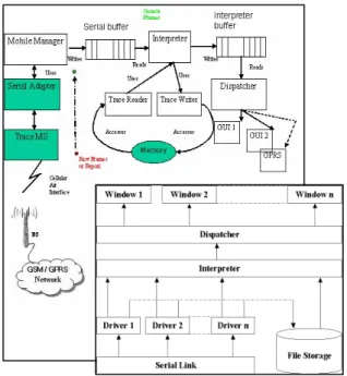
modules, which are made up of Java packages and classes; these packages have their respective functions and are dependent on one another. We present a diagram that simplifies its architecture; Figure 1 shows different stages of this architecture that frames must traverse, it also reveals the interactions between the Java classes that form the core of our software. The graphics in green represent the hardware portion while the white represent Java software classes. The trace MS, serial adapter and the memory, all in green color depict that they are all hardware. The Mobile Manager, Serial buffer, Interpreter, Interpreter buffer, Trace Writer, Trace Reader, Dispatcher and GUIs are all software written codes performing specific functions.
The raw data frames refer to the signaling frames exchanged between the trace MS and Mobile Manager via the serial adapter, they are a succession of bytes in a rough form that is meaningless to the users; it is the format of frames captures in the protocol format that is unique to the trace MS used, in this case a Sagem OT190/290 trace MS. In Figure 1 the raw frame is identified by the small red dot. The generic data frames are presented in the form of Java objects which makes it possible to be recorded in a file for future use when MS is not in the real-time mode to study a more interesting part of the frame; this frame format that has been decoded according to the GSM technical specification (GSM-TS).
Figure 1: Generalized Modular Architecture
The Mobile Manager represents a number of drivers that specifically handle the protocol format of the trace MS used; it groups the incoming raw frames into two categories. Frames-information received from the network transmitted on the logical channels and Report-is the measurement carried out by the trace MS to be reported back to the network. Report and Frame are further grouped as shown in Figure 2.
Interpreter reads. The Interpreter decodes the frame as
transmitted on the radio link as uplink, downlink, and the logical channels used to transmit the frame. It further sorts them using protocol discriminator (PD) into call control (CC),
Figure 2: Classification of Frames and Reports
mobility management (MM), radio resource (RR), session management (SM), and radio link control/medium access control (RLC/MAC). The Interpreter does not depend on the protocol used by the trace MS, but only on the GSM-TS.
For purpose of safeguarding data for future use, the Interpreter can read and write from the computer memory. The
Dispatcher makes it possible for the decoded frames and
report to be read from the interpreter buffer and progressively distributed onto each window upon their arrival as soon as the user activates the GUI or window as shown in Figure 1. The GUIs represent the point at which the users interact with the software; this is the only module that is visible to the users. Theoretically what a GUI can do is infinite and it depends on what we want the student to learn.
III. PROTOCOL PILES IN GSM AND GPRS
The GSM network layer on the MS side is divided into three sub layers, this include the connection management (CM) layer, MM layer, RR layer and the lower layer called the transmission layer. Each of these layers utilizes the function provided by the adjacent and provides enhanced functions to the next upper layer as shown in Figure 3. The RR layer manages the administration of frequencies and channels, which guarantees stable link upon handover by providing stable links between MSs and mobile switching centres (MSCs). It monitors the broadcasting control channel (BCCH), the paging channel (PCH), random access channel (RACH) administration, it requests and assigns channels, performs MS power control and synchronization as well as handover.
MM performs the assignment of the temporary mobile subscriber identity (TMSI), including the MS localization, location updating through management of subscriber location data. Authentication and identification (attach/detach) of MS
are also performed by the MM layer. The subscriber identity module (SIM), home location register (HLR) and authentication centre (AuC) are all involved in the MM activities.
Figure 3: Sub-layers of the GSM MS Network Layer Control of calls, provisioning and maintenance of services offered by the network is handled by the CM layer. Examples are the short message services (SMS) and teleservices. The CM makes use of the stable basis provided by the RR and the MM layer in order to provide services. Additional functions performed include call termination and dual tone multifrequency (DTMF) signaling, and in-call modification.
Transmission plane lies at the bottom which is the basis of any telecommunication system. It provides information transfer between cooperating machines. The transmission plane represents a domain of very short time scale events, ranging from microsecond (as in bit modulation) to seconds (in message transmission).
A. The Protocol Pile in the GSM Machines
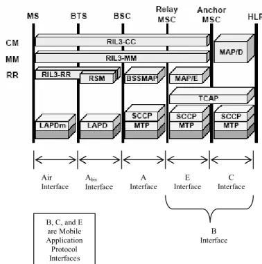
The functional layers previously described as shown in horizontal layers of bricks demarcate the protocols which can be defined on each interface (Figure 4). This work concentrates only on the radio interfaces (Um) of the GSM and
GPRS network. Figure 4 shows the entities or components that constitute the GSM network. On the horizontal axis, the GSM machines are spatially distributed with the MS on the leftmost going through various machines till the HLR. The vertical axis on the other hand is the functional planes starting from the bottom is in the transmission layer, and going up through different layers as previously described above.
For the piles of protocols on the radio interface, at the bottom, all the transmission functions use protocols between MS and the base transceiver station (BTS). The radio interface layer 3-RR (RIL3-RR) protocol which enables MS and BSC to cooperate for the management of radio resources also appears on the Abis interface.
The RIL3-MM and RIL3-CC which are upper layer protocols define the rules for signaling exchanges between the MS and the network switching subsystem (NSS) entities. They also appear at the Abis interface.
IV. DESCRIPTION AND FEATURES
Because of e constrain place on the length of this paper we will present the important features of this software that can be used to assist in teaching. We present by the use of Figures the typical figures used in presenting MO calls, NO calls, and GPRS data transfer. Figure 3 shows the
A. Presentation of Layer 2 GUI
Figure 4: Protocols across the GSM Interfaces
B. Protocol Pile in the GPRS Machines
Protocol layers in the GPRS system are divided into two planes. The transmission plane shown in Figure 5 below, is mainly used for the transfer of user data, and associated within the control procedure, like flow control and error handling. On the other hand, there is the signalling plane, used for the control and support of the transmission plane functions as well as routing and mobility management.
The Um protocol layers include the GSM radio frequency
(RF), RLC/MAC, LLC, subnetwork dependent convergence protocol (SNDCP), and the internet protocol (IP) layers. The physical radio interface includes procedures for GPRS in terms of the channel coding, cell reselection procedures and power regulations. Existing GSM functionalities take care of the modulation/demodulation and possible detection of and correction of physical medium transmission errors [2].
The GSM RF layer supports a certain number of logical channels. This layer is divided into two sub layers-the radio frequency layer (RFL), handles the radio and baseband part, while the physical link layer (PLL) manages the control of the RFL (this includes power control, synchronization, measurements, and channel coding/decoding) [1]. On top of this stack is the RLC/MAC. It is considered to be a part of the same sublayer, as it provides services for the transfer of information over the physical layer of GPRS. RLC/MAC also performs backward error correction procedures enabled by the selective retransmission of erroneous blocks. RLC provides a reliable link between MS and base station system (BSS), it deals with the block segmentation and reassembling of logical link control (LLC) data packets and buffering. MAC on the CM MM RR Transmission Air Interface B Interface Abis
Interface Interface A Interface E Interface C
B, C, and E are Mobile Application Protocol Interfaces
LLC provides a highly reliable logical link, independent of the underlying radio interface protocol to allow introduction of alternative radio solutions with minimum changes to the GPRS internal networks (e.g. EDGE); LLC also provides a highly reliable, ciphered logical link between the MS and the SGSN.
The protocol layer above the LLC is the SNDCP which performs multiplexing of data from different sources to be sent across the LLC. It maps the IP protocol to the underlying network, and the compression and segmentation of the network layer messages.
Figure 5: The GPRS transmission plane showing protocol layers and interfaces [13].
C. PDP Context
The packet data protocol (PDP) context specifies access to an external packet switching network. Within GPRS, PDP context activation is a procedure performed between the MS and the SGSN. In the first definition of GPRS PDP context is only MS-initiated. PDP context is handled by the MS, SGSN, and GGSN, which is identified by a MS’s PDP address within these entities. Multiple PDP contexts can be activated at the same time within a given MS. The MS is always GPRS-attached before PDP context activation. The MS in this case must provide the GPRS network with the access point name (APN) describing an external network that should be contacted; the APN is a domain name.
The MS is always GPRS-attached before the PDP context activation procedure as shown in Figure 6; by performing GPRS-attach, the MS makes its presence known by establishing a logical link between itself and the SGSN. It then makes itself available for SMS over GPRS, paging over GSGN, and notification of incoming GPRS data [14].
IV. DEVELOPED SOFTWARE OVERVIEW
In this section we present (few) important features of our
Figure 6: PDP Context activation from MS
developed software, to improve the teaching of protocol exchange and messages that are exchanged between the MS and the network in GSM and GPRS network. We use Sagem OT190 and OT290 trace mobiles for our trace capturing.
We developed the main GUI for the user, which consist of eight different menus that can be accessed and activated. This software is developed to be used in three different modes; the
serial mode is a real-time mode when the trace MS is
connected for trace capturing and analysis. When the serial frame window is activated, in this case it is possible to observe the raw frames as described in section III, the temporary file
mode works when the trace MS is not connected, as mentioned
previously (see Figure 1), the design of this software is such that it automatically save traces captured at the prompt of the user in this mode. In the step-by-step mode the user can display the captured traces on request, this is done at the user’s pace at the click of a button, and this function is recommended for close monitoring of events for possible decoding of the messages that are exchanged between the MS and the network.
To closely monitor, study and analyze the behavior of the MS in a GSM network, we present the following GUIs which can be activated on the Visualization menu of the main GUI.
A. Presentation of GSM Layer 3 Messages
We present GSM L3 messages to the users as shown in Figure 7, the messages on this GUI can be displayed with or without filtering. Messages that can be filtered include BCCH system information (SI), padding paging, measurement report and slow associated control channel (SACCH) SI. This GUI is developed for observing and analyzing L3 messages (frames) in an uplink or downlink direction and the protocol associated with such messages. The basic building blocks for L3 messages are provided by the protocol control entities suitably described by the sublayers of L3 as described in section III; these are RR management, CM and MM layers.
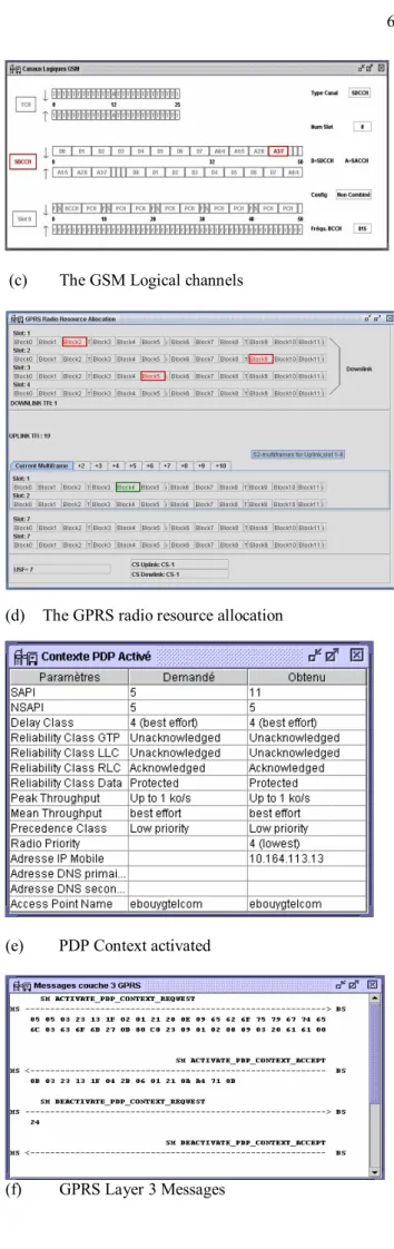
B. Presentation of the GSM Logical Channels
The result of the developed GUI is to present utilization of GSM logical channels that explains radio resource allocation
over the air interface of the GSM network during all MS oriented or network terminated services as they are in use, is shown in Figure 7(c). We present the mapping of the GSM traffic channels on the 26-multiframe for the downlink and the uplink. Also the 51 TDMA multiframe, used to carry BCCH, common control channel (CCCH) and stand alone dedicated channel (SDCCH) (with associated SACCH) is presented. This GUI was developed to automate edge of the boxes in red, green, and blue colors. When the edge of the box is in red, it shows that such frame is used in the downlink direction. Boxes displayed in green color indicate MS is communicating in the uplink direction, while blue indicates a BCCH report.
C. Presenting the GPRS Radio Resource Allocation, PDP Context Activation and GPRS layer 3Messages.
The combination of these GUIs will facilitate the understanding of the behavior of the MS during packet transfer. The allocation of radio resources on the air interface of the GPRS network can be studied using Figure 7(d), this user interface shows in the first panel, a 52-multiframe in a block of 12 including four frames for the packet timing control channel (PTCCH) and idle frames. This represents communication in the downlink direction. The next panel represents uplink direction of communication (notice that the temporary flow identity (TFI) is displayed for the uplink and downlink) , while the third panel is used to represent a slot containing packet broadcast control channel (PBCCH) and packet common control channel (PCCCH) if present. The last panel displays the uplink state flag (USF) used. In Figure 7(d) block(s) displayed in red depict(s) those used in the downlink direction by the network to the GPRS MS to transfer data, while those in green are reserved for future use by the MS. Figure 7(e) illustrates the connection parameters of GPRS MS on a network during the activation of PDP context and Figure 7(f) displays the messages exchanged between GPRS MS and the network during packet transfer.
V. TEACHING OUTLINE
A number of user interfaces have been developed to assist the user’s understanding of GSM and the GPRS cellular standards. There are currently 17 GUIs being developed for this purpose and more could still be developed, depending on what the user wants to see. The combination of these user interfaces rather than a single one had been used in ENST-Paris for students to show the format of L2 and L3 messages of the GSM and GPRS standards, the concept of frame encapsulation, allocation of the logical channels, and in particular protocol exchange on the air interfaces of these two standards. We performed several MS tasks and obtained corresponding traces, such MS tasks include dialing (only) using the MS international mobile station identity (IMSI), call connection (dedicated mode), sending and receiving SMS, paging and MS camping (monitor by switching on/off the MS), power management and timing advances when MS is in idle and dedicated mode, connection to a URL through a GPRS network using web application protocol (WAP).
We have shown and described a few of the traces obtained above. Through laboratory exercises, we have performed extensive decoding (translation of octets in the frames exchanged) using [3] – [8]; the work carried out on decoding of frames can be found in [13].
VI. CONCLUSION
We have developed user interfaces and integrate them with the existing ones (windows) to be able to study and comprehend the procedures of radio resource allocation and downlink signaling counter (DSC) [13] in GSM/GPRS systems for SAGEM OT190/OT290. We highlight the modular features of our learning software tool in Figure 3 and developed the drivers for the two trace MSs used. In Figure 3, every Driver is an independent module, which makes it possible for us to incorporate a driver for the OT 75 (supports GSM only) and OT 190/290 (supports GSM and GPRS). The main problem we foresee is the inability to read from the
Serial and Interpreter buffers (Figure 3) in the same pace as
they are written, if this does happen, some of the frames will be missed at the user platform, this was however not noticed, but we would like to ensure that it is taken care of if it does happen.
We validated the operation of this software tool by performing extensive decoding of GSM L3 frames, RLC/MAC blocks and the GPRS L3 messages using GSM TS in [13]. Clandestine testing of this learning software was only done and used for teaching purposes at the ENST-Paris, France and could not be done in South Africa because of the copyright issue. Major developments of the windows are done in French language which may also make its use difficult in South Africa.
The use of this tool allows the users to fully understand the principle of encapsulation of L2 and L3 messages in GSM and GPRS. In the future it will be possible to develop more modules for EDGE, UMTS and WiFi standards depending on the availability of trace MS for these standards.
REFERENCES
[1] E. Seur, P. Savelli, and P. Pietri, GPRS for Mobile Internet, Norwood, MA: Artech House Publisher, 2003.
[2] Hakon Gudding, “Capacity Analysis of GPRS”, Master thesis, Department of Electrical Engineering and Telecommunications, Norwegian University of Science and Technology, Norway, 2000. [3] 04.07 3GPP TS, version 6.5.1, Mobile Radio Interface Signaling Layer
3, General Aspect, Sophia Antipolis, Release 1997, Nov. 1999. [4] 04.08 3GPP Technical Specification, version 6.21.1, Mobile Radio
Interface Layer 3 Specifications, Sophia Antipolis, Release 1997, Sept. 2003.
[5] SAGEM, Serial Link Interface Specification for Test Tools, protocol version V3.11, 15 April 2004.
[6] 04.60 3GPP Technical Specification, version 6.14.0, Radio Access, General Packet Radio Service (GPRS), Mobile Station (MS)-Base Station System (BSS) Interface, Radio Link Control/Medium Access Control (RLC/MAC) Protocol, Sophia Antipolis, Release 1997, July 2002.
[7] 05.08 3GPP Technical Specification, version 6.9.0, Phase 2+, Radio Subsystem Link Control, Sophia Antipolis, Release 1997, Sept. 2000. [8] 05.05 3GPP Technical Specification, version 6.8.0, Phase 2+, Radio
Transmission and Reception, Sophia Antipolis, Release 1997, Sept. 2000.
2nd Ed.. New York: Willey & Sons, 2001.
[11] G. Heine, GSM Networks: Protocols, Terminology, and
Implementation. Norwood, MA: Artech House, 1999.
[12] X. Lagrange, P. Godlewski, and S. Tabbane, Reseaux GSM (GSM
Networks), 5th ed. Paris: Hermes Science, 2000.
[13] OJ Oyedapo, “Learning Tools for Cellular Air Interfaces (GSM, GPRS, UMTS and WLAN),” Master thesis, School of Electrical Engineering, Tshwane University of Technology, Pretoria, South Africa, 2005. [14] 03.60 3GPP TS, version 6.11.0, Group Services and System Apsects,
General Packet Radio Service (GPRS), Service description, Stage 2, Sophia Antipolis, Release 1997, 2002.
[15] Joachim Göller . (2006, Dec.). Networks (2nd ed.) [Online]. Available:
http://www2.informatik.hu-berlin.de~goeller/isdn
[16] B. Lars, M. Sibert, and B. Walke, “Software Defined Protocols Based on Generic Protocol Functions for Wired and Wireless Networks”, Software Defined Radio Technical Conference, Orlando, USA Nov. 2003.
(a) Main GUI showing the Visualization Menu
(b) GSM L3 Messages Presentation
Figure 7 (a) - (f): User Interfaces activated from the Visualization Menu
(c) The GSM Logical channels
(d) The GPRS radio resource allocation
(e) PDP Context activated
© 2007 IEEE. Personal use of this material is permitted. However, permission to reprint/republish this material for advertising or promotional purposes or for creating new collective works for resale or redistribution to servers or lists,
or to reuse any copyrighted component of this work in other works must be obtained from the IEEE.
![Figure 5: The GPRS transmission plane showing protocol layers and interfaces [13].](https://thumb-eu.123doks.com/thumbv2/123doknet/12477666.338348/5.918.474.841.79.292/figure-gprs-transmission-plane-showing-protocol-layers-interfaces.webp)