HAL Id: hal-00667841
https://hal.archives-ouvertes.fr/hal-00667841
Submitted on 8 Feb 2012
HAL is a multi-disciplinary open access
archive for the deposit and dissemination of
sci-entific research documents, whether they are
pub-lished or not. The documents may come from
teaching and research institutions in France or
abroad, or from public or private research centers.
L’archive ouverte pluridisciplinaire HAL, est
destinée au dépôt et à la diffusion de documents
scientifiques de niveau recherche, publiés ou non,
émanant des établissements d’enseignement et de
recherche français ou étrangers, des laboratoires
publics ou privés.
TEPE: a SysML language for time-constrained property
modeling and formal verification
Daniel Knorreck, Ludovic Apvrille, Pierre de Saqui-Sannes
To cite this version:
Daniel Knorreck, Ludovic Apvrille, Pierre de Saqui-Sannes. TEPE: a SysML language for
time-constrained property modeling and formal verification. Software Engineering Notes, Association for
Computing Machinery, 2011, 36 (1), pp.1-8. �hal-00667841�
Formal Verification
Daniel Knorreck, Ludovic Apvrille
Institut Telecom / Telecom ParisTech, LTCI CNRS,
2229 Route des Crˆ
etes, B.P. 193, 06904 Sophia-Antipolis Cedex, France
{daniel.knorreck, ludovic.apvrille}@telecom-paristech.fr
Pierre de Saqui-Sannes
Universit´
e de Toulouse, LAAS-CNRS, ISAE,
10 av. Edouard Belin, B.P. 54032, 31055 TOULOUSE Cedex 4, France
[email protected]
Abstract
Using UML or SysML models in a verification-centric method requires a property expression language, a formal se-mantics, and a tool. The paper introduces TEPE, a graphi-cal TEmporal Property Expression language based on SysML parametric diagrams. TEPE enriches the expressiveness of other common property languages in particular with the no-tion of physical time and unordered signal recepno-tion. TEPE is further instantiated in the AVATAR real-time UML profile. TTool, an open-source toolkit, implements a press-button ap-proach for the formal verification of AVATAR-TEPE proper-ties with UPPAAL. An elevator system serves as example.
1
Introduction
The increasing importance of real-time systems in life-critical applications has stimulated research work on modeling tech-niques that combine the friendliness of UML / SysML with the formality of verification tools such as UPPAAL. So far, the use of SysML in verification centric methods has been hampered by the poor formality of Requirement Diagrams and the lack of powerful property expression language. Thus, UML / SysML profiles commonly require the use of temporal logics (e.g., CTL) or the use of languages based on traces (e.g., the VSL language of MARTE [OMG08]) which are not always adequate to specify complex sets of sequential and parallel behaviors.
The paper extends SysML Parametric Diagrams to intro-duce TEPE1, a graphic but formal language for describing
logical and temporal properties. In TEPE, various design elements, such as blocks, attributes, and signals, can be combined together with logical (e.g., sequence of signals) and temporal operators (e.g., a time interval for receiving a signal) to build up complex but graphical properties. Moreover, TEPE may be introduced into the OMG-based SysML and a broad variety of SysML profiles. As a demonstration of this, we include TEPE in the real-time SysML profile - named AVATAR2 - which is supported by
1TEmporal Property Expression Language 2Automated Verification of reAl Time softwARe
TTool, an open-source toolkit interfaced with UPPAAL. The strength of the AVATAR-TEPE combination is that requirement capture, analysis, design, property description and verification tasks can seamlessly be accomplished in the same language, namely UML, and in the same environment [ASS09]. The designer is merely required to have minor UML skills and does not need to familiarize with formal languages like CTL or UPPAAL.
The paper is organized as follows. Section 2 surveys papers on property expression languages and explains why we do not reuse other UML / SysML diagrams such as state machines. Section 3 introduces the TEPE language. Section 4 presents the integration of the TEPE language into the AVATAR real-time profile in terms of methodology and language. Section 5 addresses the toolkit issue. Section 6 discusses an example: an elevator system. At last, Section 7 concludes the paper and outlines future work.
2
Related work
2.1
Property specification
There are several widely accepted and standardized verifica-tion oriented languages which bear some resemblance with our approach as far as support for sequential behavior is concerned. These languages mostly target the verification of HDL designs. System Verilog [AOI] provides concurrent assertions for describing behavior that spans over time. The underlying event model is based on clock ticks. However AVATAR temporal operators, either for system design or property verification, are tied to physical time, and so to state machine temporal operators.
The e-language [VDI02] somewhat extends the System Ver-ilog event model by introducing user defined events derived from behavior or other events. However, temporal expres-sions require a trigger events to be selected for condition evaluation. Our approach offers more flexibility for operators may specify several sampling events or signals respectively. Furthermore, in AVATAR, the set of sampling events may evolve over time.
PSL [AOI04] can be considered as an extension of LTL and
CTL temporal logics and the expressiveness of its temporal layer resembles the System Verilog specification language. PSL is also tightly coupled to clock based events. So called ”properties” are used to describe behavior over time and they are made up of a Boolean expression and a clock expression amongst others. However, the aforementioned languages fail to model physical time independently of clock cycles. The SystemC Verification Standard [otSVWG03] addresses the creation of test benches and allows both for random stim-ulus generation and recording of resulting transactions. To our knowledge, it does not comprise a syntax for expressing temporal properties, nor automated ways to verify them. [Smi01] advocates a nice graphical notation which aims to simplify the formalization of requirements for model check-ing. System executions are expressed in the form of timeline diagrams discriminating optional, mandatory, fail events and related constraints. As for other trace based approaches, conditional or varying system behavior cannot easily be ex-pressed. Moreover, the approach does not address real-time or performance requirements.
2.2
Property specification in UML
The MARTE profile embraces VSL [OMG08] which aims at specifying the values of constraints, properties and stereo-type attributes particularly related to non-functional as-pects. Even when used in combination with sequence dia-grams, VSL makes it cumbersome if not impossible to spec-ify complex sets of sequential behaviors.
The Rhapsody tool used by [dSV09] similarly enables for-mal verification of SysML diagrams using UPPAAL. Unlike TTool, Rhapsody does not distinguish between requirements and properties. Nor it supports a property expression lan-guage - such as TEPE - and computation operators in state machines. In terms of user-friendliness, TTool allows one to right-click on an action symbol and automatically verify the reachability of that action. In the same situation, the user of Rhapsody is obliged to enter a logic formula, which as-sumes some knowledge in logic.The OMEGA2 environment [OD09] has also strong connections with Rhapsody for it im-plements the same semantics. OMEGA2 supports require-ment diagrams as defined in SysML. Conversely ARTISAN [HH10] extends SysML to cope with continuous flows. AR-TISAN models may contain probabilities and interruptible regions, two concepts not yet supported by AVATAR. The open-source environment Topcased also enables requirement modeling in a SysML fashion [AM10].
Electronic System Level (ESL), which is an emerging elec-tronic design methodology, has stimulated research work on joint use of SysML and formal languages supported by simu-lation tools. Several papers discuss solutions where a model is designed in SysML and translated into VHDL-AMS [SCo] or Simulink [VD06]. Mechanical engineering is another area where SysML is combined with already existing domain spe-cific languages, such as Modelica or bond graphs.
2.3
Property specification with TEPE
Finally, TEPE matches a high abstraction level in contrast to languages closely tied to static sampling events, especially clock cycles [AOI][VDI02][AOI04]. The language supports reasoning in terms of high level signals, timing and the value of system variables (equations). As the objective is to ver-ify sequential behaviors - and their timing -, the property descriptions could surely rely on state machines. However, overusing UML Statecharts both for modeling and property purposes is probably not a good idea. Indeed, if property description does not rely on a different formalism, it runs the risk of being hampered by the same errors in reasoning as the model. Moreover, (1) Statecharts are not adequate to model situations where events may be received in any order, which are commonly encountered in properties, and (2), statecharts do not put an emphasis on property rela-tions, like TEPE. Apart from Statecharts, formally defined descriptions for sequential behavior fall short in UML. For example, scenario-based models like Sequence Diagrams fail to describe relations between attributes of various instances (e.g., attribute x of instance I0 is equal to attribute y of instance I1 ), and they might be inadequate for describing complex situations, in particular to reference past events. Even though Live Sequence Charts [DH01] provide more se-mantics to scenarios, modeling several acceptable traces is still cumbersome. Additionally, the integration of equations that have to be fulfilled as a function of the system behav-ior is not straightforward in UML and requires the usage of OCL, thereby circumventing the graphical notation.
3
TEPE: TEmporal Property
Ex-pression language
SysML Requirement Diagrams (RDs) structure requirements and define testcases. Basically, requirements may be linked together using << derive >> and composition relations. Requirements may also be copied from other views (<< copy >>). SysML RDs also support the definition of test-cases (that we rename ”properties”) that may be linked to requirements using the << verif y >> relation. Unfortu-nately, properties are only defined in an informal way with an identifier and a text. To address that limitation, this chapter introduces TEPE.
3.1
TEPE and Parametric Diagrams
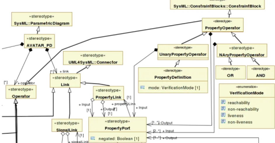
A specification in TEPE represents functional and non-functional properties in a formal way, using Parametric Diagrams. As opposed to informal SysML PDs, TEPE PDs are amenable to automated verification. A small set of operators can be leveraged to make up complex properties. In TEPE, each property is expressed as a graph of Signals, Attributes, Constraints (Equations, Logical Constraints, Temporal Constraints) and Properties. An excerpt from the meta model of TEPE PDs is depicted in Figure 1. All
stereotypes of PDs are derived from their respective SysML counterpart: Blocks, Operators, and Links interconnecting Operators. A block defines all Attributes and Signals which are referred to by Operators. Operators are assembled by means of Links which are attached to the Operator’s ports. Links are characterized by the respective type of the data they convey: Attribute, Signal and Property. Ports must obviously have the same data type as the connected Link, and two connected ports must have an opposite type (input, output).
A TEPE PD is supposed to be constructed in the following way:
1. First, Blocks are represented with their particular At-tributes and Signals subject to verification. These enti-ties have been identified during the design phase. 2. Values derived from original attributes and signals are
introduced (cf. Equation and Alias operators).
3. The reasoning about the sequential and temporal be-havior of the system is expressed in terms of logical and temporal operators connected to Signals and Properties. These logical and temporal operators can be cascaded. 4. Several Properties may be merged using logical property
operators (Conjunction, Disjunction, Property Defini-tion Operators).
5. Finally the formal property is labeled to link it to an informal SysML RD and to determine whether (non-) liveness or (non-) reachability should be verified on that property.
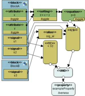
6. To avoid overloaded diagrams, constituting properties of a requirement can be spread over several diagrams. The purpose of the following example (see Figure 2) is to informally present operators of PD. The PD defines two Blocks. BlockA has two attributes x and y as well as two sig-nals s1 and s2. BlockB declares one signal called s3. A Set-ting operator declares a temporary variable which serves as a shorthand to simplify expressions. An equation imposing a constraint on the variable z is introduced as well. An Alias operator denotes the logical disjunction of signals, the result-ing signal is thus raised upon occurrence of one of the two entry signals. Two properties are logically combined using an AND operator. The first one states that upon reception of an s2 signal, the compound signal resulting from the Alias operator must be observed as well, i.e. s2 or s3. Further-more, if the s1 signal is received or the equation evaluates to false between the occurrence of s2 and the compound signal, the LS operator evaluates to false. The second property re-quires the signal s2 to be sent less than 10 time units after signal s1. The overall property is checked for liveness, which is made explicit by a Property Definition operator.
Figure 2: Example of an TEPE Parametric Diagram
3.2
TEPE: operators
TEPE operators manipulate three kinds of data: attributes, signals and properties.
• Attributes: defined in blocks at system design level, or as new attributes from existing ones (Setting).
• Signals: directly defined in blocks. Two additional sig-nals are also considered: entry(state) and exit(state). • Properties are Boolean values resulting from SysML
constraints: either Equations, or temporal / logical con-straint operators.
3.2.1 Attribute-based operators
Two operators define attributes: attribute declaration and attribute setting. The Equation operator takes attributes as input, and outputs a property. Moreover, attribute operators output a signal indicating a value change (toggle).
3.2.2 Signal-based operators
Alias operators merge several distinct Signals to one. The resulting Signal is notified upon notification of one of the constituting Signals.
SigToPropOperators introduce a partial order of transitions and a notion of time and can thus be used to limit the temporal scope of Properties. SigToPropOperators thus translate temporal behavior of Signals into a Property which can be further evaluated. Three SigToPropOperators are defined: the temporal constraint, the partial order, and the logical sequence.
Figure 1: Excerpt from the TEPE PD Meta Model
3.2.3 Property-based operators
Property Operators comprise conjunction and disjunction functions for Properties.
Property Definition Operators assign a name to a property, and specify its verification kind: (non-) reachability or (non-) liveness. This verification kind is similar to CTL quantifiers.
3.3
TEPE: signal-based operators
Two operators are of outstanding importance in TEPE: Log-ical Constraints and Temporal Constraints. They both ob-serve signals and properties after a given signal condition is met, and output another property based on that observation.
3.3.1 Logical Constraint
Inputs: set S of n signals s1. . . sn, set Sf of m signals
sf 1. . . sf m, where Sf∩ S = ∅ and a property Pi (optional),
Output : Po
The operator defines a set of transitions which may be reached irrespective of their order. Once any signal sf irst in
S is encountered, the operator requires all signals S\{sf irst}
to be observed for Po to be true. If none of the signals S is
ever received, Pois defined to be true. Furthermore, the
op-erator handles failure signals sf 1. . . sf mforcing Poto be false
in case they are notified between the first received signal of S and the last one. In addition to that, Piis required be true
during all that period, otherwise Po is set to false. A more
formal description of the operator applied to two signals s1,
s2 and failure signal sf is given in Figure 3, where T stands
for TRUE, F for FALSE and CF (Pi) denotes the change of
property Pi from true to false. Sending and reception of a
message are symbolized by exclamation and question marks respectively. The value of Po is indicated on the state
sym-bol, in the Moore machine style.
Figure 3: Semantics of Logical Constraints
3.3.2 Logical Sequence
Inputs: set S of n signals s1. . . sn, the set Sf of m signals
sf 1. . . sf m, where Sf∩ S = ∅ and a property Pi (optional),
Output : Po
This operator represents a property of a system defined in terms of a logical sequence of state transitions. It establishes an order among a given set of signals s1. . . sn, that is, it
works similarly to the Logical Constraint, apart from the fact that the order in which input signals are received is imposed.
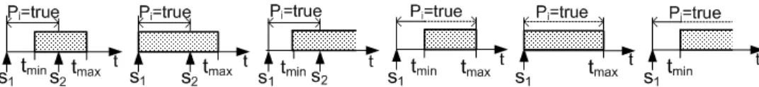
3.3.3 Temporal constraint
Inputs: two signals s1, s2 (the latter is optional), two time
values tmin, tmax (either of the two is optional) and a
prop-erty Pi (optional, considered to be true by default), Output :
Po
Depending on the provided arguments, Po is defined to be
true under the following conditions:
1. s1, s2, tmin, tmax: s2has to occur at least tmin, at most
tmax after s1and Pimust be true from the reception of
s1 to the reception of s2(Figure 4a)
2. s1, s2, tmax: s2has to occur at most tmaxafter s1and Pi
must be true from the reception of s1 to the reception
of s2 (Figure 4b)
(a) Semantics 1 (b) Semantics 2 (c) Semantics 3 (d) Semantics 4 (e) Semantics 5 (f) Semantics 6
Figure 4: Temporal Constraint Operator Semantics
3. s1, s2, tmin: s2 has to be notified at least tmin after s1
and Pi must be true from the reception of s1 to the
reception of s2(Figure 4c)
4. s1, tmin, tmax: after reception of s1, Pi must be true for
at least tminand at most tmax(Figure 4d)
5. s1, tmax: after reception of s1, Pi must be true for at
most tmax(Figure 4e)
6. s1, tmin: after reception of s1, Pi must be true for at
least tmin (Figure 4f)
4
Integrating TEPE into a UML
profile for real-time systems
4.1
The basics of AVATAR
The AVATAR profile reuses eight of the SysML diagrams (Package diagrams are not supported). It further struc-tures Sequence Diagrams using an Interaction Overview Di-agram (a diDi-agram supported by UML2, not by SysML). The AVATAR profile is syntactically and semantically defined by a meta-model. Besides a syntax, a semantics and a tool sup-port, a profile is also characterized by a methodology.
4.2
Methodology
The AVATAR methodology comprises the following stages: 1. Requirement capture. Requirements and properties
are structured using AVATAR Requirement Diagrams. At this step, properties are just defined with a specific label.
2. System analysis. A system may be analyzed using usual UML diagrams, such as Use Case Diagrams, In-teraction Overview Diagrams and Sequence Diagrams. This stage is not covered in this paper.
3. System design. The system is designed in terms of communicating SysML blocks described in an AVATAR Block Diagram, and in terms of behaviors described with AVATAR State Machines.
4. Property modeling. The formal semantics of prop-erties is defined within TEPE Parametric Diagrams (PDs). Since TEPE PDs involve elements defined in system design (e.g, a given integer attribute of a block),
TEPE PDs may be defined only after a first system de-sign has been performed.
5. Formal verification can finally be conducted over the system design, and for each testcase.
Once all properties are proved to hold, requirements, system analysis and design, as well as properties may be further refined. Thereafter, and similarly to most UML profiles for embedded systems, the AVATAR methodological stages are reiterated. Having reached a certain level of detail, refined models may not be amenable to formal verification any more. Therefore the generation of prototyping code may become the only realistic option.
4.3
AVATAR: Block and State Machine
Di-agrams
Apart from their formal semantics, AVATAR Block and State Machine Diagrams only have a few characteristics which dif-fer from the SysML ones.
An AVATAR block defines a list of attributes, methods and signals. Signals can be sent over synchronous or asyn-chronous channels. Channels are defined using connectors between ports. Those connectors contain a list of signal as-sociations.
A block defining a data structure merely contains attributes. On the contrary, a block defined to model a sub-behavior of the system must define an AVATAR State Machine.
AVATAR State Machine Diagrams are built upon SysML State Machines, including hierarchical states. AVATAR State Machines further enhance the SysML ones with tem-poral operators:
• Delay: af ter(tmin, tmax). It models a variable delay
during which the activity of the block is suspended, waiting for a delay between tmin and tmaxto expire.
• Complexity: computeF or(tmin, tmax). It models a
time during which the activity of the block actively ex-ecutes instructions, before transiting to the next state: that computation may last from tmin to tmax units of
time.
The combination of complexity operators (computeF or()), delay operators, as well as the support of hierarchical states - and the possibility to suspend an ongoing activity of a sub-state - endows AVATAR with main features for supporting real-time system schedulability analysis.
4.4
Translation to UPPAAL: the basics
The translation of a an AVATAR-TEPE specification to UP-PAAL is defined as the following tr function:
tr : BD × SM Ds × P DS 7→ U P P AALSpec
More precisely, tr takes as input one AVATAR Block Dia-gram, a set of State Machine Diagrams, and a set of Para-metric Diagrams. tr returns a UPPAAL specification. A UPPAAL specification is made upon a set of timed automata communicating using synchronized channels.
Basically, one block and its state machine are transformed into one automata. Each time two blocks can communi-cate, a channel is created between the two corresponding au-tomata. AVATAR State Machine operators are transformed into a set of transitions between automata states. In par-ticular, the use of AVATAR delay and complexity operators can be translated using UPPAAL clock initializations, state invariants, and guards on clocks.
For each property defined in a Parametric Diagram, a corre-sponding observer automata [FSsA08] is derived. The latter makes states and transitions related to verification explicit in the UPPAAL model. In so doing, proving the satisfiabil-ity of a given TEPE property is reduced to searching for the accessibility or liveness of a given observer state, using the UPPAAL verifier.
5
Toolkit
5.1
TTool
The open-source toolkit TTool [ASS09] supports several UML / SysML profiles, in particular TURTLE [ACLdSS04] and DIPLODOCUS [Apv08]. TTool offers UML modeling edition facilities, and well as press-button approaches for for-mal verification and simulation. TTool and its profiles are supported by several academic and industrial partnerships. TTool is interfaced to verification tools that implement reachability analysis and model-checking. For example, to decide whether some UML action is reachable or not, it suf-fices to right click on the corresponding action’s symbol: The UPPAAL verifier is invoked with corresponding CTL for-mula, and the result is displayed on UML diagrams.
TTool encourages the user to use viewpoints simply by se-lecting the blocks to be considered for model transformation. If a property refers to excluded entities, it is simply ignored during verification as its evaluation is impossible. Alterna-tively, the property could be considered to hold or to be violated by default.
Moreover, a very fast simulation engine has been developed for DIPLODOCUS [KAP09], and integrated into TTool. It features the animation and interactive simulation of UML diagrams [KAP10].
5.2
Extending
TTool
for
TEPE
and
AVATAR
TTool can now edit TEPE diagrams. TTool also par-tially supports the AVATAR-TEPE to UPPAAL transla-tion. Currently, AVATAR Block and State Machine dia-grams can always be translated to UPPAAL (no limitation), and AVATAR properties expressed in AVATAR Parametric Diagrams can automatically be formally checked out only when they target the reachability or liveness of one specific state of an AVATAR State Machine. Otherwise, they must be translated by hand. Their full translation is under devel-opment.
6
Case study
6.1
Requirements
As a case study, we consider an elevator system. Four func-tional safety-related requirements have been identified and modeled in a Requirement Diagram:
• Req1: The door does not open when the elevator is moving.
• Req2: The elevator does not depart with an open door. • Req3: The operational profile requires the elevator to accelerate after being set in motion and to decelerate before stopping.
• Req4: Deceleration must be accomplished between 1 and 5 seconds before the selected floor is reached.
6.2
System design
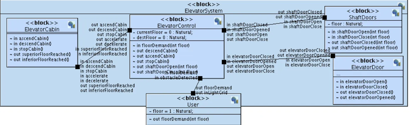
The block diagram (See Figure 5) comprises three main el-ements: The ElevatorControl block, which is charge of con-trolling the cabin of the elevator, the elevator door and the shaft doors. Three actuators are also represented as blocks: ElevatorCabin, ElevatorDoor and ShaftDoors. Furthermore, another block stands for actions taken by the user of the sys-tem. As previously stated, blocks are interconnected with signals. For instance, the ElevatorControl unit may send a signal to its environment. By explicitly connecting it to a corresponding signal defined within ElevatorCabin, the two finite state machine are able to synchronize.
6.3
Property modeling in TEPE
After having structured the system in terms of blocks, at-tributes and signals, the developer may proceed with the formal model of the properties to be verified (see Figure 6), corresponding to requirements (Req1 to Req4 ). More pre-cisely, one property corresponds to the four requirements. In Figure 6, moveElevator is declared as composite signal of ascendCabin and descendCabin; moveElevator is thus raised upon notification of one of the constituting signals. Req1
Figure 5: Elevator Block Diagram
is captured by a Logical Sequence operator receiving as in-put the sequence of the composite signal and the stopCabin signal. During that sequence, the reception of an elevator-DoorOpen signal is considered as an incorrect system be-havior. A temporal operator is dedicated to Req2 : At the instant when the cabin is set in motion (notifed by the com-posite signal), the system variable doorOpen must evaluate to false. To satisfy the operational profile requirements Req3 and Req4, a sequence operator monitors the accelerateCabin and the decelerateCabin signals. The cascading of the latter sequence operator with the one dedicated to cabin motion suggests that the sequence of accelerateCabin and deceler-ateCabin must occur when the cabin is in motion (Req3 ). A second temporal Operator accounts for Req4 : at least 1, at most 5 time units have to elapse between notification of the signals decelerateCabin and stopCabin. The results of all requirements are finally combined using an AND operator.
Figure 6: TEPE Model of the elevator’s requirements
6.4
Discussion
The case study demonstrates the applicability of TEPE lan-guage for the verification of system properties. While sharing the most important semantics with other temporal logics like CTL, TEPE enriches their expressiveness with the notion of physical time and an operator matching a set of unordered signals. The granularity and the abstraction level of dia-grams is in line with the system model; system transitions are referred to using signals and state variable modifications. These elements are familiar to the designer as he/she intro-duced them during the design phase. By combining static equations and sequential operators, a temporal scope is at-tached to the former. In our example, initial SysML informal requirements are easily translated into TEPE. A formal def-inition however opens the door for an automatic verification on the fly during simulation or by transformation into an UPPAAL model enhanced with observers. Although nothing prevents from using the textual from of TEPE, the graphical representation based on Parametric Diagrams far outreaches the latter in terms of readability. Moreover, an adequate coloring of operators facilitates the clear distinction between timed (signals) and untimed parts (properties) of the dia-gram.
7
Conclusion
The TEmporal Property Expression language, or TEPE for short, customizes SysML parametric diagrams. Properties are built up upon logical and temporal relations between block attributes and signals.
As an OMG-SysML compliant language, TEPE may be in-tegrated to a broad variety of SysML real-time profiles, such as AVATAR. AVATAR is a verification-centric profile that improves SysML’s capability to express and verify proper-ties of time-constrained systems. Unlike other real-time pro-files, AVATAR-TEPE puts the emphasis on requirement and property modeling. AVATAR further reuses SysML block di-agrams and state machines so as to distinguish between wait-ing time and computation time. AVATAR state machines also support nested states, as well as suspension. A complete
suspend/resume mechanism is currently under investigation, both in terms of language and formal verification.
Moreover, AVATAassociated with a verification centric method supported by the open-source toolkit TTool. The toolkit includes a diagram editor, a UPPAAL code genera-tor and a press-button interface to formal verification. TTool thus enables formal verification of SysML design diagrams against temporal properties expressed in TEPE. In particu-lar, the SysML model of the elevator system discussed in the paper has been developed using TTool.
Short term extension shall include automatic generation of observers from TEPE properties. We also plan to introduce a methodological assistant to guide newcomers to AVATAR and to make TTool as friendly as possible for education ac-tivities.
References
[ACLdSS04] L. Apvrille, J.-P. Courtiat, C. Lohr, and P. de Saqui-Sannes. TURTLE: A real-time UML profile supported by a formal validation toolkit. In IEEE transactions on Software En-gineering, volume 30, pages 473–487, Jul 2004. [AM10] M. Audrain and B. Marconato. Top-cased 3.4 tutorial - requirement management. In http://www.topcased.org/index.php? docu-mentsSynthesis=y&Itemid=59, 2010.
[AOI] Accellera Organization Inc. SystemVer-ilog 3.1a Language Reference Manual, www.systemverilog.org.
[AOI04] Accellera Organization Inc. Property specifi-cation language, reference manual, version 1.1. 2004.
[Apv08] L. Apvrille. TTool for DIPLODOCUS: An En-vironment for Design Space Exploration. In Proceedings of the 8th Annual International Conference on New Technologies of Distributed Systems (NOTERE’2008), Lyon, France, June 2008.
[ASS09] Ludovic Apvrille and Pierre De Saqui-Sannes. Making formal verification amenable to real-time UML practitioners. In Proceedings of the 12th European Workshop on Dependable Com-puting, Toulouse, France, May 2009.
[DH01] Werner Damm and David Harel. Lscs: Breath-ing life into message sequence charts. Formal Methods in System Design, 19(1):45–80, 2001. [dSV09] E. C. da Silva and E. Villani. Integrando SysML e model checking para v&v de software cr´ıtico espacial. In Brasilian Symposium on Aeropspace Engineering and Applications, S˜ao Jos´e dos Campos, SP, Brasil, September 2009.
[FSsA08] B. Fontan, P. De Saqui-sannes, and L. Apvrille. Timing requirement description diagrams for real-time system verification. In ERTSS - Em-bedded Real Time Software and Systems, Jan 2008.
[HH10] M. Hause and J. Holt. Testing solutions with UML/SysML. In http://www.artist-embedded.org/docs/Events/2010/UML AADL /slides/Session1 Matthew Hause.pdf, 2010. [KAP09] Daniel Knorreck, Ludovic Apvrille, and
Re-naud Pacalet. Fast simulation techniques for design space exploration. In Objects, Com-ponents, Models and Patterns, volume 33 of Lecture Notes in Business Information Pro-cessing, pages 308–327. Springer Berlin Heidel-berg, 2009.
[KAP10] Daniel Knorreck, Ludovic Apvrille, and Re-naud Pacalet. An interactive system level sim-ulation environment for Systems on Chip. In ERTSS - Embedded Real Time Software and Systems, May 2010.
[OD09] Iulian Ober and Iulia Dragomir. OMEGA2: A new version of the profile and the tools (regular paper). In UML&AADL’2009 - 14th IEEE International Conference on Engineer-ing of Complex Computer Systems, pages 373– 378, Potsdam, June 2009. IEEE.
[OMG08] OMG. A UML profile for MARTE, beta 2, www.omg.org. 2008.
[otSVWG03] Members of the SystemC Verification Working Group. SystemC Verification Standard Speci-fication Version 1.0e, www.systemc.org. 2003. [SCo] SysML companion. In
http://www.realtimeatwork.com/?page id=683. [Smi01] Margaret H. Smith. Events and constraints:
a graphical editor for capturing logic proper-ties of programs. In In Proceedings of the 5th International Symposium on Requirements En-gineering, pages 14–22, 2001.
[VD06] Yves Vanderperren and Wim Dehaene. From UML/SysML to matlab/simulink: current state and future perspectives. In DATE ’06: Proceedings of the conference on Design, au-tomation and test in Europe, pages 93–93, 3001 Leuven, Belgium, Belgium, 2006. European Design and Automation Association.
[VDI02] Verisity Design Inc. e Lan-guage Reference Manual, www.ieee1647.org/downloads/prelim e lrm.pdf. 2002.