HAL Id: hal-00725492
https://hal.archives-ouvertes.fr/hal-00725492
Submitted on 27 Aug 2012
HAL is a multi-disciplinary open access
archive for the deposit and dissemination of
sci-entific research documents, whether they are
pub-lished or not. The documents may come from
teaching and research institutions in France or
abroad, or from public or private research centers.
L’archive ouverte pluridisciplinaire HAL, est
destinée au dépôt et à la diffusion de documents
scientifiques de niveau recherche, publiés ou non,
émanant des établissements d’enseignement et de
recherche français ou étrangers, des laboratoires
publics ou privés.
The bit interleaved coded modulation module for
DVB-NGH: enhanced features for mobile reception
Catherine Douillard, Charbel Abdel Nour
To cite this version:
Catherine Douillard, Charbel Abdel Nour. The bit interleaved coded modulation module for
DVB-NGH: enhanced features for mobile reception. ICT 2012: 19th International Conference on
Telecom-munications, Apr 2012, Jounieh, Lebanon. pp.1 - 6, �10.1109/ICTEL.2012.6221327�. �hal-00725492�
The Bit Interleaved Coded Modulation Module for
DVB-NGH
Enhanced features for mobile reception
Catherine Douillard and Charbel Abdel Nour
Lab-STICC laboratory (UMR CNRS 6285) Institut Mines-Télécom; Télécom BretagneUniversité Européenne de Bretagne Brest, France
{catherine.douillard, charbel.abdelnour}@telecom-bretagne.eu
Abstract— This paper describes the main features of the DVB-NGH Bit-Interleaved Coded Modulation (BICM) module. This latter is derived from a sub-set of DVB-T2 BICM components with additional features intended to first lower receiver complexity and power consumption and then to increase receiver robustness over mobile reception. Therefore, the long code block size was removed, a different range of coding rates was chosen, non-uniform constellations were adopted in order to provide shaping gain, and the principle of signal space diversity was extended to four-dimensional rotated constellations. Moreover the structure of the time interleaver offers the possibility to significantly increase the interleaving depth, a feature required for mobility over terrestrial and satellite links.
Keywords-DVB-NGH, BICM, LDPC code, non-uniform constellations, 4D rotated constellations, time interleaver.
I. INTRODUCTION
In 2009, when the DVB-NGH Call for Technologies [1] was issued, two technical state-of-the-art DVB standards could be used as a starting point for DVB-NGH: DVB-SH [2] and DVB-T2 [3]. Both standards include state-of-the-art Bit-Interleaved Coded Modulation (BICM) modules. In particular, they both use a capacity approaching coding scheme: a turbo coding scheme is used in DVB-SH and a DVB-S2-like LDPC code was adopted in DVB-T2. Moreover, the DVB-NGH Commercial Requirements [4] mention the possibility to combine DVB-NGH and DVB-T2 signals in one Radio Frequency (RF) channel. The natural way for this combination calls for the use of the so-called Future Extension Frames (FEF) of DVB-T2. Although a DVB-T2 FEF can contain BICM components totally different from the DVB-T2 BICM module, the existence of combined DVB-T2/NGH receivers finally pushed the elaboration of a DVB-NGH physical layer strongly inspired by DVB-T2.
According to the above-mentioned considerations, DVB-NGH was designed to provide an extension of the DVB-T2 system capabilities, to ease the introduction of TV services to mobile terminals within an existing terrestrial digital TV network. In particular, keeping reasonable receiver complexity and power consumption and increasing robustness of mobile reception have guided the choice for the BICM components.
Therefore, the BICM module in the DVB-NGH standard is mainly derived from a sub-set of DVB-T2 BICM components, with a set of additional features allowing for higher robustness and coverage.
Section II describes the overall structure of the BICM module in DVB-NGH. Sections III to VI provide details for its elementary components: FEC code, bit interleaver, bit-to-cell demultiplexer, constellations and time interleaver. The description mainly focuses on the new features and performance of NGH compared to T2. Section VI presents some performance results and section VII concludes the paper.
II. OVERALL VIEW OF THE DVB-NGHBICMMODULE
In the communication theory literature, BICM is the state-of-the-art pragmatic approach for combining channel coding with digital modulations in fading transmission channels [5]. The modulation constellation can thus be chosen independently of the coding rate. The DVB-NGH BICM encoder consists essentially of:
a forward-error correcting (FEC) code allowing transmission errors to be corrected at the receiver side, a bit interleaver whose function is to spread the coded bits within a FEC block in order to avoid undesirable interactions between the bits to be mapped to the same modulation constellation point,
a bit-to-cell mapper, mapping groups of coded bits to modulation constellation points,
a set of interleavers intended to fight against channel impairments, e.g. caused by impulsive noise or time-varying channels, by spreading cell error bursts over several FEC blocks.
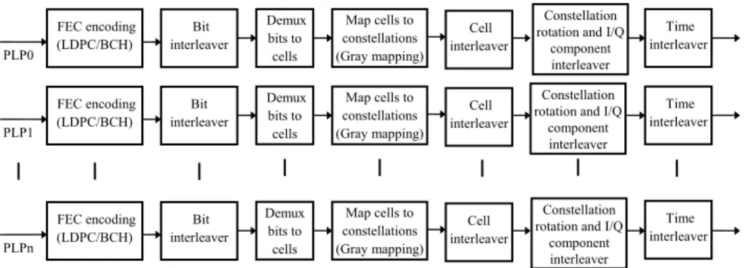
In DVB-NGH, as in DVB-T2, the input to the BICM module consists of one or more logical data streams. Each logical data stream is carried by one Physical Layer Pipe (PLP) and is associated with a given modulation constellation, a given FEC mode and a given time interleaving depth. The DVB-NGH BICM module structure for data PLPs is described in Fig. 1.
Part of the work dedicated to the BICM module of DVB-NGH was funded by the Eurêka /Celtic-plus ENGINES project.
Figure 1. DVB-NGH BICM module structure.
III. FORWARD ERROR CORRECTION
FEC coding in the first generation of DVB standards was based on convolutional and Reed-Solomon codes. In the second generation, more powerful codes are used, calling for the serial concatenation of a Bose-Chaudhuri-Hocquenghem (BCH) code and Low Density Parity Check (LDPC) code. These codes were designed to provide a quasi error free quality target, defined as “less than one uncorrected error-event per transmission hour at the throughput of a 5 Mbit/s single TV service decoder” and approximately corresponding to a transport stream Frame Error Ratio RER < 10-7.
LDPC codes are capacity-approaching codes calling for iterative decoding techniques. The DVB-x2 LDPC codes [6] ensure low-complexity encoding due to their Irregular-Repeat Accumulate (IRA) structure [7]. Moreover, an efficient structure of the parity-check matrix allows for a high level of intrinsic parallelism in the decoding process. In order to reach the quasi error free target without any change in the slope of the error rate curves, an outer t-error-correcting BCH code with
t = 10 or 12 has been added to remove residual errors.
In the main DVB-x2 standards, two FEC block lengths have been defined, Nldpc = 64800 and Nldpc = 16200 bits. In DVB-NGH, only the short 16200-bit LDPC codes have been implemented in order to reduce receiver complexity. Furthermore, the code rate values were chosen to uniformly cover the range 5/15 (1/3) to 11/15, thus providing equidistant performance curves with respect to signal-to-noise ratio. The set of coding rates and blocks sizes are summarized in Table I.
TABLE I. DATA CODING PARAMETERS FOR DVB-NGH
LDPC code rate BCH uncoded block size Kbch LDPC uncoded block size Kldpc BCH t-error correction 5/15 (1/3) 5 232 5 400 12 6/15 (2/5) 6 312 6 480 12 7/15 7 392 7 560 12 8/15 8 472 8 640 12 9/15 (3/5) 9 552 9 720 12 10/15 (2/3) 10 632 10 800 12 11/15 11 712 11 880 12
The low and high coding rates, 1/3, 2/5, 3/5, 2/3 and 11/15 are directly taken from DVB-S2. On the contrary, rates 7/15 and 8/15 call for new codes specific to DVB-NGH. The BCH code is identical to the one used in DVB-T2 for the short block size.
IV. BIT INTERLEAVER AND BIT-TO-CELL DEMULTIPLEXER
DVB-NGH inherited the bit interleaver structure from DVB-T2. It is a block interleaver applied at the LDPC codeword level, consisting of parity interleaving followed by column-twist interleaving. If basic block interleaving – column-wise writing and row-wise reading – were applied directly to the LDPC codewords, many constellation symbols would contain multiple coded bits participating to the same LDPC parity equations, entailing a performance loss in channels with deep fading. To avoid this degradation, the parity interleaver permutes parity bits in such a way that the redundancy part of the parity-check matrix has the same structure as the information part. Then, the information bits and the parity interleaved bits are column-wise serially written into the column-twist interleaver, and read out serially row-wise. The write start position of each column is twisted by an integer value tc, depending on the code size, the constellation and the column number. In DVB-NGH, parity interleaving is applied to all constellations and for all coding rates, as it was shown to improve low error rate performance in fading channels. Column-twist interleaving is used for all constellations but QPSK.
As in DVB-T2, an additional bit-to-cell de-multiplexer is inserted between the bit interleaver and the constellation mapper. It divides the bit stream at the output of the bit interleaver into a number of sub-streams which is a multiple of the number of bits per constellation cell. In DVB-NGH, the bit-to-cell de-multiplexing parameters have been specifically tuned in order to allow a finer optimization for each constellation size and code rate.
V. MODULATION CONSTELLATIONS
NGH has inherited the four constellations of DVB-T2: QPSK, 16-QAM, 64-QAM and 256-QAM. Except for the 256-QAM, they can be implemented according to two different modes: conventional non-rotated or rotated constellations. Moreover, two new features have been added to the existing scheme: the adoption of non-uniform 64- and 256-QAM and the extension of the rotated constellation principle to four dimensions for QPSK and high coding rates.
A. Non-Uniform QAM Constellations
Non-uniform constellations are introduced to bridge the observed gap between capacity curves of uniform constellations and the Shannon limit. In fact, when the received FEC encoding (LDPC/BCH) Bit interleaver Demux bits to cells Map cells to constellations (Gray mapping) PLP0 FEC encoding (LDPC/BCH) Bit interleaver Demux bits to cells Map cells to constellations (Gray mapping) PLP1 FEC encoding (LDPC/BCH) Bit interleaver Demux bits to cells Map cells to constellations (Gray mapping) PLPn Cell interleaver Time interleaver Cell interleaver Time interleaver Cell interleaver Time interleaver Constellation
rotation and I/Q component interleaver Constellation rotation and I/Q
component interleaver
Constellation rotation and I/Q
component interleaver
signal is perturbed by Gaussian-distributed noise, the mutual information expression is maximised for a Gaussian distribution of the transmitted signal. Applying this assumption leads to the famous Shannon capacity formula. However, the distribution of conventional QAM constellations is far from Gaussian: it is both discrete, as only a limited number of signal values are transmitted, and uniform, since the constellation points are regularly spaced and transmitted with equal probabilities.
Non-uniform constellations try to make the transmitted constellation distribution appear “more” Gaussian. Called
shaping gain, the corresponding improvement adds up to the
coding gain of coded modulation schemes. It has been shown that the shaping gain of discrete constellations in AWGN channel cannot exceed 10 log(e/6) 1.53 dB [8]. Two main shaping techniques have been investigated so far: using a classical constellation with a regular distribution of the signal points and transmitting the signal points with different probabilities or using a constellation whose signal points are non-uniformly spaced and transmitting all the signal points with the same probability. The non-uniform constellations proposed in DVB-NGH belong to the second category.
Constellation point coordinates are chosen to maximise the BICM capacity of the underlying QAε. δet’s detail the approach in the simple example of 16-QAM. Non-uniform 16-QAM has not been adopted in DVB-NGH, but the optimisation principle is simpler to explain in this case. If we consider that uniform 16-QAε uses positions {−γ,−1,+1,+γ} on each axis, then we can make a non-uniform version having positions {− ,−1,+1,+ }, using only one parameter . For any particular signal-to-noise ratio (SNR), we can plot the BICM capacity as a function of . For example, Fig. 2 shows the BICM capacity of the non-uniform 16-QAM at a SNR of 10 dB. equal to γ corresponds to the uniform case, while the maximum capacity is obtained for a value of between 3.35 and 3.4. Selecting the values of yielding the maximum capacity for a large range of SNRs can provide the basis for the construction of an adaptive non-uniform 16-QAM.
Figure 2. BICM capacity curve as a function of non-uniformity parameter for 16-QAM in AWGN at 10 dB SNR.
When considering higher order constellations, where larger gains are expected, the capacity maximisation involves more than one uniformity parameter: 3 parameters for non-uniform 64-QAM whose coordinates on I and Q axes are{− ,− ,−α,−1,+1,+α,+ ,+ } and 7 parameters for non-uniform 256-QAM whose coordinates on I and Q axes are
{− ,− ,− ,− ,− ,− ,−α,−1,+1,+α,+ ,+ ,+ ,+ ,+ ,+ }. A solution to this problem was provided numerically for a large range of SNR. As a consequence of the dependence of the non-uniform constellation points on the SNR, a given non-non-uniform constellation cannot provide the maximum coding gain for any operation point and accordingly for any code rate. Therefore a specific non-uniform constellation has been defined for each code rate. The corresponding constellation mappings are given in Table II and Table III.
TABLE II. CONSTELLATION MAPPING OF THE I AND QCOMPONENTS FOR THE UNIFORM AND NON-UNIFORM 64-QAM
I/Q values Binary mapping 1 0 0 1 0 1 1 1 1 1 1 0 0 1 0 0 1 1 0 0 1 0 0 0 Uniform -7 -5 -3 -1 1 3 5 7 Non-Uniform Coding Rate 1/3 -7.2 -5.2 -1.9 -1.4 1.4 1.9 5.2 7.2 2/5 -7.4 -4.9 -2.0 -1.3 1.3 2.0 4.9 7.4 7/15 -7.5 -4.6 -2.3 -1.0 1.0 2.3 4.6 7.5 8/15 -7.5 -4.6 -2.4 -0.9 0.9 2.4 4.6 7.5 9/15 -7.5 -4.6 -2.5 -0.9 0.9 2.5 4.6 7.5 2/3 -7.4 -4.7 -2.6 -0.9 0.9 2.6 4.7 7.4 11/15 -7.3 -4.7 -2.7 -0.9 0.9 2.7 4.7 7.3
The I/Q coordinates don’t have the form {− ,− ,−α,−1,+1,+α,+ ,+ } since a normalization operation was performed in order to keep the same transmit power as for the uniform constellations.
Fig. 3 shows the performance gain of the non-uniform 256-QAM in the AWGN channel with respect to the classical constellation.
Figure 3. Performance comparison of uniform and non-uniform 256-QAM over AWGN channel. Both curves display the required SNR to achieve a
FER=10-4 after LDPC decoding.
B. Rotated Constellations
1) A reminder about 2-dimensional rotated constellations
When using conventional QAM constellations, each signal component, in-phase I (real) or quadrature Q (imaginary), carries half of the binary information held in the signal. When a constellation signal is subject to a fading event, I and Q components fade identically. In case of severe fading, the information transmitted on I and Q components suffers an irreversible loss. When a rotation is applied to the constellation, components I and Q both carry the whole binary content of the signal, as every point in the constellation now has its own projections over the I and Q axes. The rotation is performed by
9 10 11 12 13 14 15 16 17 18 19 20 21 Es/N0(dB) 2.0 3.0 4.0 5.0 6.0 B it p e r c h a n n e l u s e Uniform 256-QAM Non-uniform 256-QAM R = 1/3 R = 7/15 R = 2/5 R = 11/15 R = 2/3 R = 3/5 R = 8/15 Non-uniformity parameter BICM capacity bit/channel use
TABLE III. CONSTELLATION MAPPING OF THE I AND QCOMPONENTS FOR THE UNIFORM AND NON-UNIFORM 256-QAM I/Q values Binary mapping 1 0 0 0 1 0 0 1 1 0 1 1 1 0 1 0 1 1 1 0 1 1 1 1 1 1 0 1 1 1 0 0 0 1 0 0 0 1 0 1 0 1 1 1 0 1 1 0 0 0 1 0 0 0 1 1 0 0 0 1 0 0 0 0 Uniform -15 -13 -11 -9 -7 -5 -3 -1 1 3 5 7 9 11 13 15 Non-Uniform Coding Rate 1/3 -17.2 -12.6 -9.7 -9.3 -3.8 -4.1 -2.5 -2.4 2.4 2.5 4.1 3.8 9.3 9.7 12.6 17.2 2/5 -17.3 -13.1 -9.4 -8.8 -4.2 -4.3 -2.1 -2.1 2.1 2.1 4.3 4.2 8.8 9.4 13.1 17.3 7/15 -17.5 -13.1 -9.2 -8.2 -4.7 -4.6 -1.6 -1.7 1.7 1.6 4.6 4.7 8.2 9.2 13.1 17.5 8/15 -17.5 -13.0 -9.3 -8.1 -5.0 -4.6 -1.6 -1.5 1.5 1.6 4.6 5 8.1 9.3 13 17.5 9/15 -16.7 -13.1 -10.3 -8.0 -5.9 -4.2 -2.3 -0.9 0.9 2.3 4.2 5.9 8 10.3 13.1 16.7 2/3 -16.7 -13.1 -10.3 -8.0 -5.9 -4.2 -2.3 -0.9 0.9 2.3 4.2 5.9 8 10.3 13.1 16.7 11/15 -16.6 -13.1 -10.3 -8.0 -6.0 -4.2 -2.4 -0.9 0.9 2.4 4.2 6 8 10.3 13.1 16.6
multiplying each I/Q component vector by a 2x2 orthogonal matrix: Q I Q I x x y y cos sin sin cos
Next, the Q component of the resulting vector is cyclically delayed by one cell within the FEC block. Consequently, due to the subsequent effect of the cell and time interleavers, the two copies or projections of the signal are sent separately in order to benefit from time or frequency diversity respectively. With this technique, the diversity order of BICM is doubled compared to the case of non-rotated constellation.
2) 4-dimensional rotated constellations
In DVB-NGH, the constellation diversity has been extended with the adoption of so-called four Dimensional Rotated Constellations (4D-RC). Moreover the cyclic shift delay applied to the quadrature Q component is replaced by a more sophisticated I/Q component interleaver providing a better time separation and channel diversity, when time-frequency slicing (TFS) [9] or multi-frame interleaving is enabled. The 4D rotation is performed by multiplying two vectors consisting of the I/Q components of two adjacent input cells by a 4x4 orthogonal matrix:
Q I Q I Q I Q I x x x x a b b b b a b b b b a b b b b a y y y y 1 1 0 0 1 1 0 0
The four dimensional rotation matrix is characterized by a single parameter r taking values in range [0,1], referred to as the rotation factor, which is defined as:
2 2
/
3b a
r
Since the rotation matrix is orthogonal, a2 b3 2 1. Thus, a and b are derived from r as
) 1 ( 1 r a ) 1 ( 3 r r b
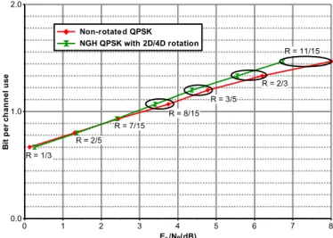
The optimal value for r was actually chosen to minimise the bit error rate at the demapper output in Rayleigh fading channels. With 4D-RC, the diversity order of the BICM is quadrupled in comparison with non-rotated constellations. Over fading channels, they only provide gain when used with very low constellation sizes such as QPSK and high code and they show high robustness in case of deep fades or erasures. From a complexity point of view, at the receiver side, M 2 four-dimensional Euclidean distances have to be computed by the demapper for a M-QAM Finally the use of 4D-RC in DVB-NGH has been restricted to 4D-QPSK for code rates greater than or equal to 8/15. Table IV summarizes the rotated constellations modes and parameters adopted in the standard.
TABLE IV. SUMMARY OF THE ROTATED CONSTELLATION MODES IN
DVB-NGH
Modulation Code rate
1/3 2/5 7/15 8/15 3/5 2/3 11/15
QPSK 2D ( = 29.0 deg.) 4D (r = 0.4)
16QAM 2D ( = 16.8 deg.)
64QAM 2D ( = 8.6 deg.)
256QAM N/A
Fig. 4 shows the performance gain due to the rotated constellations modes of DVB-NGH in a fast fading memoryless Rayleigh channel.
Figure 4. Performance gain due to the constellation rotation modes of DVB-NGH over memoryless Rayleigh channel. Both curves display the
required SNR to achieve a FER=10-4 after LDPC decoding.
0 1 2 3 4 5 6 7 8 Es/N0(dB) 0.0 1.0 2.0 B it p e r c h a n n e l u s e Non-rotated QPSK NGH QPSK with 2D/4D rotation R = 1/3 R = 7/15 R = 2/5 R = 11/15 R = 2/3 R = 3/5 R = 8/15
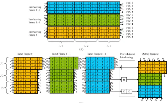
Figure 5. Time interleaving for NIU = 3 in the hypothetical case where each FEC codeword length contains 16 cells and each IF contains 4 FEC blocks C. Cell Interleaving and I/Q Component Interleaving
1) Cell Interleaving: The cell interleaver first applies a
pseudo-random permutation in order to uniformly spread the cells in the FEC codeword. It aims at ensuring an uncorrelated distribution of channel distortions and interference along the FEC codewords in the receiver. This pseudo-random permutation varies from one FEC block to the next. In contrast to DVB-T2, it is placed before the I/Q component interleaver.
2) I/Q Component Interleaving: It is applied after the 2D or
4D rotation and is performed on each FEC block independently according to the following three steps:
1. The I and Q components of the cells belonging to a FEC block are separately written column-wise into two matrices of the same size;
2. A cyclic shift is applied to each column of the Q-component matrix;
3. The two matrices are read out synchronously row-wise and complex cells are formed by each read pair of a real (I) and an imaginary (Q) component. The number of rows NR in the matrices and the values of the cyclic shifts depend on whether TFS is enabled or not. When TFS is off, the component interleaver distributes the
D = 2 or 4 dimensions of each constellation evenly over the
FEC block, the resulting distance between the D components of each constellation signal being (1/D)th of the FEC length. In this case, NR is equal to D, and the cyclic shifts of all columns are equal to D/2. When TFS is on, parameter NR is a function of the number of RF channels NRF and the cyclic shift can take
NRF-1 different values. The values of these parameters are chosen to ensure that the D dimensions of each constellation signal are transmitted over all possible combinations of RF channels.
VI. TIME INTERLEAVING
The time interleaver (TI) is mainly intended to provide protection against impulsive noise and time-selective fading. It is placed at the output of the I/Q component interleaver or at the output of the cell interleaver, depending on whether rotated constellations are used or not. It operates at PLP level and the TI parameters can vary from a PLP to another.
The total size of the memory for time de-interleaving all PLPs associated with a service cannot exceed 218 memory units for the terrestrial link. A memory unit contains one cell with 64-QAM and 256-QAM modulation. Since QPSK and 16-QAM constellations can afford coarser cell quantization than 64-QAM and 256-QAM, for these low-order constellations a memory unit consists of a pair of two consecutive cells. This case is referred to as pair-wise interleaving. It allows higher time diversity for QPSK and 16-QAM constellations, since the TI memory can store up to 219 cells.
The core element is a block row-column interleaver, as in DVB-T2. However, DVB-NGH additionally offers the possibility to combine a convolutional interleaver on top of the core element when interleaving over several NGH frames is enabled. The Interleaving Frame (IF) contains the cells collected for one NGH frame. Since the data rate of each PLP can vary, each IF can contain a variable number of FEC blocks. In the simplest case, the IF is implemented as a single block interleaver. However, this configuration limits the maximum data rate because of the above-mentioned size limitation. To increase the data rate, it is therefore possible to divide the IF into several block interleavers before it is mapped to one NGH-frame. Conversely, for low data rate services, longer time interleaving and hence higher time diversity can be achieved by spreading the IF over several NGH frames. Then, the overall TI is implemented as a combination of a convolutional interleaver with a block interleaver. Fig. 5 illustrates this combined structure.
(a) (b) 1 1 1 1 1 1 1 1 1 1 1 1 1 1 1 1 2 2 2 2 2 2 2 2 2 2 2 2 2 2 2 2 3 3 3 3 3 3 3 3 3 3 3 3 3 3 3 3 4 4 4 4 4 4 4 4 4 4 4 4 4 4 4 4 1 1 1 1 1 1 1 1 1 1 1 1 1 1 1 1 2 2 2 2 2 2 2 2 2 2 2 2 2 2 2 2 3 3 3 3 3 3 3 3 3 3 3 3 3 3 3 3 4 4 4 4 4 4 4 4 4 4 4 4 4 4 4 4 1 1 1 1 1 1 1 1 1 1 1 1 1 1 1 1 2 2 2 2 2 2 2 2 2 2 2 2 2 2 2 2 3 3 3 3 3 3 3 3 3 3 3 3 3 3 3 3 4 4 4 4 4 4 4 4 4 4 4 4 4 4 4 4 FEC 1 FEC 2 FEC 3 FEC 4 FEC 1 FEC 2 FEC 3 FEC 4 FEC 1 FEC 2 FEC 3 FEC 4 Interleaving Frame k - 2 Interleaving Frame k - 1 Interleaving Frame k IU 1 IU 2 IU 3 1 1 1 1 1 1 2 2 2 2 2 2 3 3 3 3 3 3 4 4 4 4 4 4 IU 1 IU 2 IU 3 1 1 1 1 1 2 2 2 2 2 3 3 3 3 3 4 4 4 4 4 1 1 1 1 1 2 2 2 2 2 3 3 3 3 3 4 4 4 4 4 1 1 1 1 1 1 2 2 2 2 2 2 3 3 3 3 3 3 4 4 4 4 4 4 1 1 1 1 1 2 2 2 2 2 3 3 3 3 3 4 4 4 4 4 1 1 1 1 1 2 2 2 2 2 3 3 3 3 3 4 4 4 4 4 D D 1 1 1 1 1 1 2 2 2 2 2 2 3 3 3 3 3 3 4 4 4 4 4 4 1 1 1 1 1 2 2 2 2 2 3 3 3 3 3 4 4 4 4 4 1 1 1 1 1 2 2 2 2 2 3 3 3 3 3 4 4 4 4 4
Input Frame k Input Frame k - 1 Output Frame k
1 1 1 1 1 1 2 2 2 2 2 2 3 3 3 3 3 3 4 4 4 4 4 4 1 1 1 1 1 2 2 2 2 2 3 3 3 3 3 4 4 4 4 4 1 1 1 1 1 2 2 2 2 2 3 3 3 3 3 4 4 4 4 4
Input Frame k - 2 Convolutional Interleaving
The cells to be interleaved are written row-wise into the TI memory, FEC block by FEC block (see Fig. 5(a)). The IF is then partitioned intoNIU Interleaver Units (IU). Each IU is passed in one of the delay lines of the convolutional interleaver and the cells are afterwards read column-wise, as shown in Fig. 5(b). Each input IF is therefore spread over NIU NGH frames. This combined block/convolutional TI structure allows for time interleaving depths greater than 1 sec on the terrestrial segment. The depth can be increased to up to 10 sec for the satellite link, since the TI memory limitation is then 221 memory units.
VII. PERFORMANCE RESULTS
Fig. 6 and Fig. 7 show simulated performance of the DVB-NGH BICM in AWGN and Rayleigh channels compared to the unconstrained Shannon capacity [10] and DVB-H. The curves display the required SNR to achieve a FER=10-4 after LDPC decoding. Over AWGN channel, DVB-NGH outperforms the first generation by around 2.0 to 2.5 dB. Over a Rayleigh fading channel, the gain ranges from 3.0 to 7.0 dB. The gap to Shannon capacity is larger over a Rayleigh fading channel.
Figure 6. Required SNR to achieve a FER=10-4 after LDPC decoding over
AWGN channel. Comparison with the Shannon limit and DVB-H.
Figure 7. Required SNR to achieve a FER=10-4 after LDPC decoding over
Rayleigh fading channel. Comparison with the Shannon limit and DVB-H.
VIII. CONCLUSION
The BICM module of DVB-NGH has been devised to extend DVB-T2 operation range to lower SNRs. Moreover, the design of the BICM components has been guided by the need to increase robustness for mobile reception and to keep reasonable receiver complexity and power consumption. The overall performance of the BICM module has only been partially assessed so far. The next step involves the thorough performance evaluation in mobile channels and in quasi-error free conditions.
ACKNOWLEDGMENT
The authors wish to thank Jonathan Stott from Jonathan Stott Consulting, Peter Moss from BBC, Mihail Petrov from Panasonic, and Marco Breiling from Fraunhofer IIS, for their valuable help.
REFERENCES
[1] Digital Video Broadcasting (DVB) TM-H NGH, Call for Technologies
(CfT), v 1.0 19, November 2009, available at
http://www.dvb.org/technology/dvb-ngh/DVB-NGH-Call-for-Technologies.doc.
[2] Digital Video Broadcasting (DVB), Framing Structure, channel coding and modulation for satellite services to handheld devices (SH) below 3 GHz, ETSI EN 302 583, v 1.2.1, Dec. 2011.
[3] Digital Video Broadcasting (DVB), Frame structure channel coding and modulation for a second generation digital terrestrial television broadcasting system (DVB-T2), ETSI EN 302 755, v1.3.1, Oct. 2011. [4] Digital Video Broadcasting (DVB) CM-NGH, Commercial
Requirements for DVB-NGH, v 1.01, June 2009, available at http://www.dvb.org/technology/dvb-ngh/DVB-NGH-Commercial-Requirements.pdf.
[5] A. Guillén i Fàbregas, A. Martinez and G. Caire , Bit-Interleaved Coded
Modulation, Foundations and Trends in Communications and
Information Theory, Vol. 5, No 1-2, pp 1-153, Now publishers, 2008. [6] M. Eroz, F.-W. Sun, and L.-N. Lee, “An innovative low-density
parity-check code design with near-shannon-limit performance and simple implementation,” IEEE Trans. Commun., vol. 54, no 1, pp. 13–17, Jan. 2006.
[7] H. Jin, A. Khandekar, and R.J. McEliece, “Irregular Repeat–Accumulate Codes,” in Proc. 2nd Int’l Symp. on Turbo Codes and Related Topics, pp.
1-8, Brest, France, Sept. 2000.
[8] G. D. Forney Jr. and L.-F. Wei, “εultidimensional constellations – Part I: Introduction, figures of merit and generalized cross constellations,” IEEE Journal on Select. Areas in Commun., vol. 1, no 6, Aug. 1989. [9] M. Makni, J. Robert and E. Stare, “Performance analysis of time
frequency slicing,” 14th ITG Conf. on Electronic Media Technology
(CEMT), pp. 1-6, Dortmund, Germany, March 2011.
[10] C. E. Shannon, “Communication in the presence of noise,” Proc. Institute of Radio Engineers, vol. 37 (1): pp. 10–21, Jan. 1949.
0 1 2 3 4 5 6 7 8 9 10 11 12 13 14 15 16 17 18 19 20 21 -1 -2 Es/N0(dB) 0.0 1.0 2.0 3.0 4.0 5.0 6.0 B it p e r c h a n n e l u s e Shannon capacity QPSK, DVB-H QPSK, DVB-NGH 16QAM , DVB-H 16QAM , DVB-NGH 64-QAM , DVB-H Non-uniform 64-QAM , DVB-NGH Non-uniform 256-QAM , DVB-NGH 0 1 2 3 4 5 6 7 8 9 10 11 12 13 14 15 16 17 18 19 20 21 22 23 24 25 26 27 28 29 Es/N0(dB) 0.0 1.0 2.0 3.0 4.0 5.0 6.0 B it p e r c h a n n e l u s e Shannon capacity QPSK, DVB-H QPSK, DVB-NGH 16QAM , DVB-H 16QAM , DVB-NGH 64-QAM , DVB-H Uniform 64-QAM , DVB-NGH Uniform 256-QAM , DVB-NGH

![Fig. 6 and Fig. 7 show simulated performance of the DVB- DVB-NGH BICM in AWGN and Rayleigh channels compared to the unconstrained Shannon capacity [10] and DVB-H](https://thumb-eu.123doks.com/thumbv2/123doknet/12517584.341606/7.893.61.431.458.889/simulated-performance-rayleigh-channels-compared-unconstrained-shannon-capacity.webp)
