HAL Id: inria-00449747
https://hal.inria.fr/inria-00449747
Submitted on 22 Jan 2010
HAL is a multi-disciplinary open access
archive for the deposit and dissemination of
sci-entific research documents, whether they are
pub-lished or not. The documents may come from
teaching and research institutions in France or
abroad, or from public or private research centers.
L’archive ouverte pluridisciplinaire HAL, est
destinée au dépôt et à la diffusion de documents
scientifiques de niveau recherche, publiés ou non,
émanant des établissements d’enseignement et de
recherche français ou étrangers, des laboratoires
publics ou privés.
Constraint-Driven Instructions Selection and
Application Scheduling in the DURASE system
Kevin Martin, Christophe Wolinski, Krzysztof Kuchcinski, Antoine Floch,
François Charot
To cite this version:
Kevin Martin, Christophe Wolinski, Krzysztof Kuchcinski, Antoine Floch, François Charot.
Constraint-Driven Instructions Selection and Application Scheduling in the DURASE system. 20th
IEEE International Conference on Application-specific Systems, Architectures and Processors, (ASAP
2009), Jul 2009, Boston, United States. pp.145-152, �10.1109/ASAP.2009.19�. �inria-00449747�
Constraint-Driven Instructions Selection and Application Scheduling in the
DURASE system
Kevin Martin, Christophe Wolinski University of Rennes I, Irisa, Inria
France
{kmartin,wolinski}@irisa.fr
Krzysztof Kuchcinski Dept. of Computer Science
Lund University, Sweden [email protected]
Antoine Floch, François Charot University of Rennes I, Irisa, Inria
France
{floch,charot}@irisa.fr
Abstract
This paper presents a new constraint-driven method for computational pattern selection, mapping and application scheduling using reconfigurable processor extensions. The presented method is a part of DURASE system (Generic Environment for Design and Utilization of Reconfigurable Application-Specific Processors Extensions). The selected processor extensions are implemented as specialized proces-sor instructions. They correspond to computational patterns identified as most frequently occurring or other interesting patterns in the application graph. Our methods can han-dle both time-constrained and resource-constrained schedul-ing. Experimental results obtained for the MediaBench and MiBench benchmarks show that the presented method en-sures high speed-ups in application execution.
1. Introduction
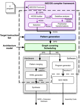
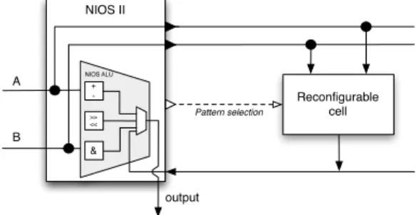
Our DURASE system enables automatic synthesis of ap-plication specific processor extensions that speed-up applica-tion’s execution. The system carries out also corresponding source code transformations to match the newly synthesized extensions. Finally, the synthesized extensions are tightly connected to a target processor and used through newly created instructions (see Figure 2 for example of the NIOS II processor and its extension). The design flow adopted in the DURASE system is presented in Figure 1. The input to the DURASE system is an application code written in C, a target processor instruction set and an architecture model. The output is a processor extension and application specific instructions for accessing this extension. The processor ex-tension is built using a merged pattern implementing all the selected computational patterns. Our system generates also an interface to the processor and the transformed application source code, including application specific instructions.
Our design process involves identification of computa-tional patterns and selection of specific patterns that speed up application execution. The pattern identification and se-lection are executed in two consecutive steps. In the first step, we explore typical computational patterns and identify
Hardware Software
GECOS compiler framework
Pattern generation
Graph covering Scheduling
GECOS Front-end
HCDG builder Dataflow analyser
Polyhedral transformations Selection CDFG HCDG HCDG Polyhedric HCDG HCDG Architecture model HCDG DIPS Pattern merging VHDL generator Synthesis GCC NIOS Program generator SPS NIS merged patterns VHDL Modified C Assembly Code DURASE flow NIOS + Extension bitstream C program Target Instruction Set
Figure 1. Generic hardware and software extension set generation flow
the most useful ones for a given application. The identified computational patterns are then used in the mapping and scheduling step where a subset of patterns is selected for implementation. In this paper, we present our new method for computational patterns selection, application mapping and application scheduling.
The developed DURASE system uses advanced technolo-gies, such as algorithms for graph matching and graph
!""#$!"%&$'((($')%*+),%-.),/$0.)1*+*)2*$.)$344/-2,%-.)564*2-1-2$786%*96:$3+2&-%*2%;+*6$,)<$=+.2*66.+6
!"#$%#&#'(")*+',-""*.*'"")*/000 12/*!"-!!")(3435-'"")-!)
merging (recently developed by our laboratories [24]) to-gether with constraints programming methods. Our system uses also a generic compilation platform GECOS recently extended by polyhedral transformations [7]. The internal representation of the DURASE system is the Hierarchical Conditional Dependency Graph (HCDG) capturing both the application control-flow and data-flow. This representation has been used previously for high-level synthesis [11], [13]. It supports formal optimizing graph transformations and allows to identify a larger amount of mutual exclusiveness information useful for conditional resource sharing. More-over, thanks to particular transformations, it is possible to minimize the influence of syntactic variance on synthesis results. In the HCDG graph nodes are guarded by boolean conditions and polyhedrons depending on loop indexes and parameters. After data-flow analysis [6], each read statement in a graph has a set of possible source contributions relying on their execution contexts and polyhedral conditions. After specific transformations loops are totally or partially unrolled to generate an HCDG which is an input for the pattern generator. NIOS II Reconfigurable cell Pattern selection NIOS ALU + ->> << & A B output
Figure 2. The ASIP “NIOS II” processor with its exten-sion Merged patterns datapath Control Clk Pattern selection
Figure 3. The architecture of an extension In this paper, we consider the architecture model of an ASIP processor with an extended instruction set. Extended instructions implement identified and selected computational patterns and can be executed sequentially with the ASIP
core instructions [23]. Our generic simplified architecture is depicted in Figure 2. It is composed of one functionally reconfigurable cell implementing a set of computational pat-terns (selected by the DURASE system) connected directly to the processor’s data-path. The selected patterns are merged by our merging procedure [24] before synthesis. The cell contains also registers (Figure 3) for the case when the generated patterns have more than two inputs and one output (case of the NIOS II). The number of registers and the structure of interconnections are application-dependent.
The paper is organized as follows. In section 2 the related work on pattern identification, selection and scheduling is discussed. Section 3 introduces briefly our method and dis-cusses constraint programming that is used in our approach. Pattern identification is discussed in section 4. Section 5 presents how pattern selection and scheduling are modeled. Section 6 presents experimental results. Finally, conclusions are presented in section 7.
2. Related Work
Related work includes both research on pattern generation for control and data-flow graphs as well as research on graph matching. We start our review from pattern generation and selection and then discuss related work on graph matching. Previous research on pattern extraction and selection, such as [1], [4], [10], is characterized by combined pattern match-ing and pattern generation for ASIPs. In [10], this is achieved with clustering that uses information on frequency of node type successions. Authors of [1] and [4] use an incremental clustering that uses different heuristic approaches with the common aim of identifying frequently occurring patterns.
Another method is presented in [2] where the pattern searching algorithm identifies a big pattern using convex-ity and input/output constraints. Some improvements of this method were proposed in [3]. Pattern searching under input/output constraints is also used in [18]. The basic algorithm starts from each exit node of the basic block and constructs a sub-graph by recursively trying to include parent nodes. The assembled sub-graph is considered as a potential new instruction. The quality of this instruction is then determined by their system. In [8], a set of Multiple Input Single Output sub-graphs (MaxMISO) is identified first. Each MaxMISO sub-graph is not contained in any other MISO sub-graph. In the next step a candidate set composed of two-input/one-output MISOs found inside the MaxMISO set is selected. Finally, using the selected candidates the application graph is partitioned by a nearly-exhaustive search method using the branch-and-bound algorithm. A complete processor customization flow was presented in [15] where patterns are clustered, one after the other, making some local decisions.
In the method presented in [9] the patterns are incremen-tally assembled by adding the neighbor nodes to existing
matches corresponding to non isomorphic patterns formed in the previous iteration.
Our approach is radically different. We generate all non isomorphic patterns satisfying all the imposed architectural and technological constraints starting from each node in the graph. The selection of the patterns from all generated patterns is controlled by smart filtering process similarly to the one presented in [22]. The smart filtering process uses information derived by a special method that is based on sub-graph isomorphism constraints and constraints program-ming.
Pattern selection, binding and scheduling are computation-ally difficult problems and therefore most researchers use heuristic approaches, such as greedy algorithms, simulated annealing, genetic algorithms and tabu search. Recently several interesting approaches have been proposed. Wang et.al. uses ACO (Ant Colony Optimization) algorithm [21] and Guo et.al. [9] a heuristic algorithm based on maximum independent set of a conflict graph.
Our approach for pattern selection, binding and schedul-ing is completely defined usschedul-ing a constraint model. We use match selection constraints along with other mapping and scheduling constraints. Then the problem can be solved using either complete or heuristic methods. In our previously presented UPak system [23], we also applied constraint programing but current approach, based on a new problem modeling, removes previous drawbacks. Specifically, it is not necessary to define, so called, “dummy nodes” that significantly reduces application graphs used for scheduling. Moreover, our new method removes appearance of “phantom matches” that appeared in specific cases due to difficulties of interpreting results given by graph matching constraints. Different types of morphism between graphs and sub-graphs have been extensively studied and many algorithms and methods have been proposed. Graph isomorphism can be solved by assigning specially constructed labels, that reflect graph structure, to nodes of the graphs and, if needed, perform search to find isomorphism. This approach is used by the program called nauty [17] as well as constraint programming approach that uses a similar method [19]. This method is rather efficient and can find isomorphism for many graphs quickly but it cannot be used for sub-graph matching problems.
The first algorithm for sub-graph isomorphism has been developed by Ullmann in [20]. Larossa and Valiente [14] studied sub-graph isomorphism problem and methods for solving it using constraint satisfaction. They explored four different solving approaches that have really full look ahead characteristics.
The VF2algorithm that can be used for both graph and sub-graph isomorphism has been developed by authors of [5]. This algorithm can be described be means of State Space Representation (SSR). In each state a partial mapping solution is maintain and only consistent states are kept.
These states are generated using feasibility rules that remove pairs of nodes that cannot be isomorphic. The comparison between nauty andVF2shows that neither of two algorithms is superior. Depending of graph characteristics one of them is better than the other. We use very similar method to this used byVF2but we extend the set of rules to be able to handle both undirected and directed graphs as well as different types of “ports” that connect edges in the graph. This is necessary in electronic design when non-symmetric operations, such as “–” are used.
3. Background
3.1. Constraint programming approach
In our work we use constraint satisfaction methods imple-mented in constraint programming environment JaCoP [12]. A constraint satisfaction problem is defined as a 3-tuple
S= (V,D,C) where V = {x1,x2, . . . ,xn} is a set of
vari-ables,D= {D1,D2, . . . ,Dn} is a set of finite domains (FD),
andC is a set of constraints. Finite domain variables (FDV) are defined by their domains, i.e. the values that are possible for them. A finite domain is usually expressed using integers, for example x :: 1..7. A constraint c(x1,x2, . . . ,xn) ∈Camong
variables ofV is a subset of D1×D2×...×Dnthat restricts
which combinations of values the variables can simultane-ously take. Equations, inequalities and even programs can define a constraint.
Especially in this paper we use the graph matching con-straint GraphMatch. This constraint defines conditions for (sub-)graph isomorphism between target and pattern graphs (the pattern graph can be defined as a set of separate sub-graphs). It has been implemented using a pruning algorithm developed for this special purpose [22] and used in our UPaK system.
A solution to a CSP is an assignment of a value from variable’s domain to every variable, in such a way that all constraints are satisfied. The specific problem to be modeled will determine whether we need just one solution, all solutions or an optimal solution given some cost function defined in terms of the variables.
The solver is built using constraints own consistency methods and systematic search procedures. Consistency methods try to remove inconsistent values from the domains in order to reach a set of pruned domains such that their com-binations are valid solutions. Each time a value is removed from a FD, all the constraints that contain that variable are revised. Most consistency techniques are not complete and the solver needs to explore the remaining domains for a solution using search.
Solutions to a CSP are usually found by systematically assigning values form variables domains to the variables. It is implemented as depth-first-search. The consistency method is called as soon as the domains of the variables for
// Inputs: G(N,E)-- application graph,
// N-- set of nodes,
// E-- set of edges,
// DIPS-- Definitively Identified Pattern Set,
// CPS-- Current Pattern Set,
// TPS-- Temporary Pattern Set
// ns-- pattern seed node
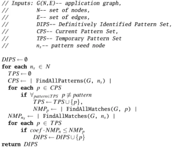
DIPS ← /0 for eachns ∈ N T PS ← /0 CPS ←| FindAllPatterns(G,ns) | for eachp ∈ CPS if ∀pattern∈TPS p %≡ pattern T PS ← TPS ∪ {p}, NMPp←| FindAllMatches(G, p) | NMPns←| FindAllMatches(G,ns) | for eachp ∈ TPS if coe f · NMPn≤ NMPp DIPS ← DIPS ∪ {p} returnDIPS
Figure 4. Pattern identification process. a given constraint are pruned. If a partial solution violates any of the constraints, backtracking will take place, reducing the size of the remaining search space.
4. Pattern Generation
Pattern generation is defined, in our approach, for an acyclic application graph G = (N,E) where N is a set of nodes and E is a set of edges. These graphs represent our HCDG representations. A pattern is a subgraph P = (Np,Ep)
of graph G where Np⊆ N and Ep⊆ E. Pattern P is also
sub-graph isomorphic to sub-graph G. This sub-sub-graph isomorphism is found, in our system, by defining a set of constraints and finding solutions to them [16].
The pattern generation process is depicted in Figure 4. In the first step of this algorithm, all computational pat-terns formed around each seed node ns∈ N satisfying all
architectural and technological constraints are identified. It is also possible to identify patterns for representative seed nodes using different heuristics but this is not considered in this paper. This is carried out by FindAllPatterns(G, n) function that is implemented using constraint programming. In the next step, the temporary pattern set (T PS) is ex-pended by non-isomorphic patterns coming from the current pattern set (CPS). Finally, only patterns whose numbers of matches in the application graph is high enough comparing to the number of matches obtained for single node patterns, composed of their seed nodes, are added to the definitively identified pattern set (DIPS). The number of matches of a given pattern in the application graph is also obtained using the constraint programming method implemented by function FindAllMatches(G, n). We use for this purpose our special graph matching constraints developed for UPaK system [23].
5. Pattern Selection and Scheduling
Selection of computational patterns and application scheduling is carried out using application graph G and a set of definitively identified patterns DIPS produced by pattern generation step. To model pattern selection and scheduling problems it is necessary to know which pattern match can cover each node n ∈ N. This information is obtained by the procedure from Figure 6. After execution of this procedure, each node n ∈ N has an associated matchesn set containing all matches that can cover it.
The information about these matches is gathered using constraint programming method. We use our graph matching constraints for this purpose.
!" !# !$ %" %
&
!""#$!%&'() !""#*+,() %' !' !( !) !* !+ !, !-%* %( %) %# %+& &
& &
&
&
&&
&
&&
& &
&
&
Figure 5. Identified and selected matches for example from Figure 7.
Obviously, in the final covering of graph G each node n ∈ N can only be covered by one match since we do not allow overlapping matches. Figure 5, for example, depicts possible and selected matches for example from Figure 7. Gray stars represent possible matches while black stars indicate selected matches. We model selection of a given match in a final schedule using finite domain variable msel
associated to each match m ∈ M, where M is a set of all matches. The value of variable msel= 1 if match m is
selected or 0 otherwise. Constraint (1) enforces requirement that each node can only be covered by one match.
∀n ∈ N :
∑
m∈matchesn
msel = 1 (1)
5.1. Pattern selection
In this paper, we are interested in selecting these compu-tational patterns that can achieve fastest possible sequential schedule for a given application and a processor. This can be obtained by minimizing the cost function defined by the equation (2) where the match delay (mdelay) depends on the
architecture model and is discussed in detail in section 5.2. The pattern selection problem in this case corresponds to
// Inputs: G=(N,E)-- application graph,
// DIPS-- Definitively Identified Pattern Set
// Mp-- set of matches for pattern p,
// M-- set of all matches,
// matchesn-- set of matches that could cover the noden,
M ← /0
for eachp ∈ DIPS
Mp←FindAllMatches(G, p)
M ← M ∪ Mp
for eachm ∈ M
for eachn ∈ m
matchesn← matchesn∪ {m}
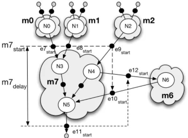
Figure 6. Procedure for finding all matches in an appli-cation graph. N0 N1 N2 N3 N5 N6 N4 m7delay m7start e7
start e8start e9start
e10start e11start e12start m6 m7 m0 m1 m2
Figure 7. Example of the non-convex match.
the graph covering problem where all nodes must be covered and the sum of the delays of the matches covering the graph is minimal. Once the matches for covering the application graph has been selected the scheduling can be easily done using, for example list scheduling that is used in this paper.
ExecutionTime =
∑
m∈M
msel· mdelay (2)
We can also select computational patterns for resource-constrained scheduling. In this case, ExecutionTime is lim-ited by ExecutionTimemax constant and the number of
dif-ferent selected computational patterns is minimized. This number is computed by constraint (4) where variable ps= 1
if pattern p has been selected by at least one match m for covering the graph (3).
∀p ∈ DIPS :
∑
m∈Mp msel >0 ⇔ ps= 1 (3) NumberOfPatterns =∑
p∈DISP ps (4)Computational patterns identified by our method might be non-convex. These patterns cannot be selected for
imple-mentation since they do not follow interface timing require-ments. All non-convex patterns are automatically excluded as possible matches using their data dependencies for inputs and outputs. This is achieved by defining input/output timing constraints on pattern interface. We first assign finite domain variable estart to each edge e ∈ E of the application graph.
This variable defines start time of a match when all data are available and has no meaning for non input/output match edges. It can be considered as a variable assigned to a new graph node assigned to the edge. The match execution is modeled by constraint (5)
msel= 1 ⇒ ∀e∈minestart= mstart∧ ∀e∈moutmstart+ mdelay≤ estart
(5) where variable mstart defines start time for execution of
match m and variable mdelay specifies its delay. Set min
is a set of input edges of the match, i.e., edges that are application inputs or an edge source node that does not belong to the pattern. Set mout is a set of output edges
of the match, i.e, edges that are either application out-puts or an edge destination nodes that does not belong to the pattern. For example, if match m7 in Figure 7 is
selected then m7start= e7start= e8start= e9start= e10start
and m7start+ mdelay ≤ e11start∧ mstart+ mdelay≤ e12start.
This is not possible because at the same time match m1 must be selected and this leads to contradiction e10start≤ e12start
indicating that output must be available before input is available. Thus, match m7 cannot be selected for application graph from Figure 5.
5.2. Match execution time modeling
Our system supports two architecture models (A and B). In model A a processor extension, implementing all selected patterns, has no registers. All operands needed for pattern execution are stored in internal processor registers. These operands are fetched from processor registers and all results are written back to these registers. In model B, the processor extension has its own registers to store its data. Processor instructions, represented by one node patterns, use internal processor registers as in model A but the processor extension can store its data in its internal registers. Results produced by patterns and used by processor instructions are stored, however, in internal processor registers. In this model, the number of additional processor cycles needed for data trans-fers is reduced but architecture complexity is higher since the number of external registers and the number of external connections is higher.
Match m delay, mdelay, expressed in processor cycles, is
composed of three parts as depicted in equation (6).
mdelay=δinm+δm+δoutm (6)
whereδmis execution time for match m whileδinmandδoutm
represent read and write time of input and output operands for match m respectively.
While execution time for a match (δm) is the same for both
architectures their transfer times are different. For model A, and match m ∈ M read and write transfer times are constants and are specified by equations (7)-(8).
δinm= ! |pred(m)|/in_PerCycle"− 1 (7) δoutm= ! |last(m)|/out_PerCycle"− 1 (8)
where pred(m) is a set of direct predecessor nodes of match m in graph G, in_PerCycle is the number of register read operations per processor cycle, last(m) is a set of terminal nodes of match m, out_PerCycle is the number of register write operations per processor cycle. NIOS II processor has in_PerCycle = 2 and out_PerCycle = 1. Thus, if a match execution time is δm= 1, m_PredN = 2 and last(m) = 1
then match delay is mdelay= 1.
For model B read and write transfer times are variable. Read transfer time is specified in equations (9)-(10) and equations (11)-(13) specify write time.
IN =
∑
n∈pred1(m) nsel (9) δinm= !IN/in_PerCycle" − 1 (10) ∀n ∈ last(m) :∑
m∈succ1(n) msel>0 ⇔ Bn= 1 (11) OUT =∑
n∈last(m) Bn (12) δoutm= !OUT /out_PerCycle" − 1 (13)where pred1(m) defines a set of one node matches that are predecessors of match m in graph G, succ1(n) defines a set of one node matches that are successors of node n in graph G. The value of variable IN is equal to the number of required read operations from processor internal registers. These accesses are necessary because the data was produced by processor instructions corresponding to one node matches. The value of variable OUT is equal to the number of write operations to processor internal registers. These accesses are necessary because the data will be used by the standard processor instructions corresponding to one node matches.
Figure 8 presents an example corresponding to partially unrolled FIR filter. The figure depicts application graph covered with automatically generated patterns and the set of patterns. Figure 9 depicts schedules for models A (left schedule) and B (right schedule). Matches, executed on the processor and on the processor extension, are grouped separately. The additional cycles needed for the data com-munication between the processor and its extensions as well as data transfers are also presented.
!"#$%$& '() *" *" +,, '() *" *" '() *" *" +,, +,, '() *" *" +,, '() *" *" !"#$%$& +,, '() *" *" '() *" *" -.& /(# /(# +,, +,, +,, '() *" *" +,, *" /(# '() *" *" '() *" *" /(# !"#$%$& '() *" *" +,, /(# !"#$%$& -.& /(# /(# +,, *" +,, *" *" '+#0.12345 '+#0.1236 '+#0.1237 '+#0.1238 '+#0.1239 '+#0.123: '+#0.123;<
Figure 8. Example graph covered with selected pat-terns. ! " # $ % & ' ( ) * "! "" "# "$ "% "& "' "( ") "* #! +,-./") ./") 01 ./( ./( 01 ./' ./' 01 ./& ./& 01 ./% ./% 01 ./$ ./$ 01 ./#! 01 2,3 01 01 2,3 01 01 2,3 456755 01 01 01 01 01 01 01 2,3 2,3 0182,3 9:3;1<021< 2,3 9:3;1<021< ./") ./") ./( ./( ./' ./' ./& ./& ./% ./% ./$ ./$ 01 ./#! ! " # $ % & ' ( ) * "! "" "# "$ "% "& 01 01 01 2,3 2,3 2,3 01 2,3 01 2,3 01 2,3 01 456755 0182,3 +,-.=3>?@12A@$@3?=3@0<@;:;>,3;B@01@3?C;;@>D>-;<E 21;@>D>-;@1;;B;B@F2C@3C=1<F;C@ .=3>?@12A@$@3?=3@0<@;:;>,3;B@01@3G2@>D>-;<E 12@=BB03021=-@>D>-;<@F2C@3C=1<F;C@1;;B;B
Figure 9. Example graph scheduling for models A and B.
Table 1. Results obtained for MediaBench and MiBench benchmark sets compiled for NIOS target processor with DURASE system.
2 in / 1 out 4 in / 2 out
model A model B model A model B
Benchmarks Nodes cycles coef identified selected coverage cycles speedup selected coverage cycles speedup coef identified selected coverage cycles speedup selected coverage cycles speedup
JPEG Write BMP Header 34 34 0 6 2 82% 14 2.42 2 82% 14 2.42 0 66 2 88% 12 2.83 3 88% 12 2.83
JPEG Smooth Downsample 66 78 0 5 2 19% 68 1.14 2 19% 68 1.14 0 49 4 95% 44 1.77 4 100% 35 2.22
JPEG IDCT 250 302 0.5 28 10 76% 214 1.41 10 76% 134 2.25 0.5 254 13 83% 141 2.36 15 89% 112 2.69
EPIC Collapse 274 287 0 11 8 68% 165 1.74 8 68% 165 1.74 0 111 11 71% 156 1.83 14 71% 159 1.8
BLOWFISH encrypt 201 169 0.5 11 3 74% 90 1.87 3 74% 90 1.87 0 153 8 90% 81 2.08 7 92% 73 2.31
SHA transform 53 57 0 5 3 64% 28 2.03 3 64% 28 2.03 0 48 8 98% 22 2.59 6 95% 17 3.35
MESA invert matrix 152 334 0.5 2 2 10% 320 1.04 2 10% 320 1.04 0.5 53 9 65% 262 1.27 9 65% 243 1.37
FIR unrolled 67 131 0 3 2 9% 126 1.04 2 9% 126 1.04 1 10 2 94% 98 1.30 2 97% 67 1.95
FFT 10 18 0 0 - - - 0 12 2 60% 10 1.80 2 60% 10 1.80
Average 50% 1.5 50% 1.7 83% 2 84% 2.3
Table 2. Results obtained for MediaBench and MiBench benchmark sets with UPaK system.
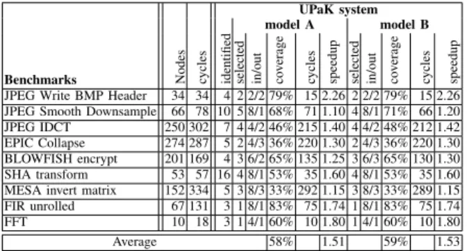
UPaK system model A model B Benchmarks Nodes cycles identified selected in/out coverage cycles speedup selected in/out coverage cycles speedup JPEG Write BMP Header 34 34 4 2 2/2 79% 15 2.26 2 2/2 79% 15 2.26 JPEG Smooth Downsample 66 78 10 5 8/1 68% 71 1.10 4 8/1 71% 66 1.20 JPEG IDCT 250 302 7 4 4/2 46% 215 1.40 4 4/2 48% 212 1.42 EPIC Collapse 274 287 5 2 4/3 36% 220 1.30 2 4/3 36% 220 1.30 BLOWFISH encrypt 201 169 4 3 6/2 65% 135 1.25 3 6/3 65% 130 1.30 SHA transform 53 57 16 4 8/1 53% 35 1.60 4 8/1 53% 35 1.60 MESA invert matrix 152 334 5 3 8/3 33% 292 1.15 3 8/3 33% 289 1.15 FIR unrolled 67 131 3 1 8/1 83% 75 1.74 1 8/1 83% 75 1.74 FFT 10 18 3 1 4/1 60% 10 1.80 1 4/1 60% 10 1.80
Average 58% 1.51 59% 1.53
6. Experimental results
We have carried out extensive experiments to evaluate both the quality of the generated patterns and the possible speed-up when implementing them as specialized instruc-tions. We used applications from MediaBench and MiBench benchmark sets, written in C and compiled by the DURASE system for the ALTERA NIOS target processor. The results were compared with those obtained by the UPAK system (Table 2). This system does not consider constraints on num-ber of inputs and outputs. The experiments were carried out for A and B model architectures and for patterns generated under different architectural and technological constraints showing the space exploration capabilities of the DURASE system.
Table 1 presents the results obtained for the benchmark sets. It shows the number of patterns identified and selected in order to obtain maximal application execution
speed-ups, the corresponding graph coverages and the application execution speed-ups. The results were obtained under con-straints that the maximal number of patterns does not exceed 10 and the patterns critical path is not longer than 15ns. The critical path corresponds to three processor cycles for the Nios2Fast processor running at 200MHz on Stratix2 Altera FPGA. In each experiment, coefficient coe f (algorithm from Figure 4) was chosen according to the application graph’s properties. It is high if there are a lot of frequently occurring patterns and small otherwise. Sign “-” in the table indicates that only one node patterns have been identified and selected and that the overall application is executed on the NIOS processor. Two types of patterns were used for experiments. The first type is limited to at most two inputs and one output patterns and the second type includes patterns with at most four inputs and two outputs For the first case, additional cycles for data transfer between NIOS processor and its ex-tensions are not needed. In the second case, data transfers are sometimes necessary but the overall applications’ execution times were reduced.
Table 2 shows results obtained by the UPaK system that constraints only the number of nodes in the generated patterns. It can be noticed that our new method generates excellent patterns. The number of selected patterns is small and the graph coverage is high. When four input and two output patterns had been allowed, the average graph cov-erage of 84% was even better than the one obtained with our UPaK system that does not support the generation of patterns under architectural and technological constraints (see column in/out). The applications’ average execution speed-up also increased to 2.3 (3.35 for the SHA transform). These are excellent results for a processor running at 200 MHz on the FPGA board (the number of operators on the critical paths must be small in order to be executed during
one processor cycle) and applications with small inherent parallelism.
7. Conclusion
In this paper, we have presented a new approach to auto-matic selection of application-specific processor extensions. We have also shown how applications are mapped and scheduled on these new architectures. Our current approach is based on a new problem modeling that removes the draw-backs of previous formulations. The important novelty of our current approach comparing to our previously presented method (implemented in UPak system [23]), is its ability to remove so called “dummy nodes” and eliminate “phantom matches”. Absence of “dummy nodes” significantly reduces the size of application graphs used for scheduling. “Phantom matches”, on the other hand, appeared in specific cases and created difficulties to interpret results generated by graph matching constraints. As a result, the current system is able to map and schedule applications with large numbers of patterns while improving the application graph coverage and increasing the applications’ execution speed-up. Our experiments confirm above advantages over UPaK system. Graph coverage was increased on average from 69% to 84% and the execution of applications was accelerated on average from 1.53 to 2.3 (for the Nios2Fast processor running at 200MHz on Stratix2 Altera FPGA).
References
[1] M. Arnold and H. Corporaal. Designing domain specific processors. In Proceedings of the 9th International Workshop
on Hardware/Software CoDesign, pages 61–66, Copenhagen,
April 2001.
[2] K. Atasu, L. Pozzi, and P. Ienne. Automatic application-specific instructionset extensions under microarchitectural constraints. In 40th Design Automation Conference (DAC), 2003.
[3] P. Biswas, S. Banerjee, N. Dutt, L. Pozzi, and P Ienne. ISEGEN: Generation of high-quality instruction set exten-sions by iterative improvement. In 42nd Design Automation
Conference (DAC), 2005.
[4] N. Clark, H. Zong, and S. Mahlke. Processor acceleration through automated instruction set customization. In 36th
Annual International Symposium on Microarchitecture, 2003.
[5] L. P. Cordella, P. Foggia, C. Sansone, and M. Vento. A (sub)graph isomorphism algorithm for matching large graphs.
IEEE Trans. Pattern Anal. Mach. Intell., 26(10):1367–1372,
2004.
[6] Paul Feautrier. Dataflow analysis of array and scalar refer-ences. International Journal of Parallel Programming, 20, 1991.
[7] GeCoS. Generic compiler suite - http://gecos.gforge.inria.fr/. [8] Y. Guo. Mapping applications to a coarse-grained recon-figurable architecture. In PhD Thesis, University of Twent,
Eindhoven, Netherlad, September 8, 2006.
[9] Y. Guo, G. Smit, H. Broersma, and P. Heysters. A graph covering algorithm for a coarse grain reconfigurable system. In Languages, Compilers, and Tools for Embedded Systems
(LCTES’03), San Diego, California, June 11-13, 2003.
[10] R. Kastner, A. Kaplan, S. O. Memik, and E. Bozorgzadeh. In-struction generation for hybrid reconfigurable systems. ACM
Trans. Des. Autom. Electron. Syst., 7(4), 2002.
[11] Apostolos A. Kountouris and Christophe Wolinski. Efficient scheduling of conditional behaviors for high-level synthesis.
ACM Trans. Des. Autom. Electron. Syst., 7(3):380–412, 2002.
[12] K. Kuchcinski. Constraints-driven scheduling and resource assignment. ACM Transactions on Design Automation of
Electronic Systems (TODAES), 8(3):355–383, July 2003.
[13] K. Kuchcinski and Ch. Wolinski. Global approach to assign-ment and scheduling of complex behaviors based on HCDG and constraint programming. Journal of Systems Architecture, 49(12–15):489–503, 2003.
[14] J. Larrosa and G. Valiente. Constraint satisfaction algorithms for graph pattern matching. Mathematical Structures in
Com-puter Science, 12:403–422, 2002.
[15] R. Leupers, K. Karuri, S. Kraemer, and M. Pandey. A design flow for configurable embedded processors based on optimized instruction set extension synthesis. In DATE, 2006. [16] K. Martin, Ch. Wolinski, K. Kuchcinski, A. Floch, and F. Charot. Constraint-driven identification of application specific instructions in the DURASE system. In SAMOS IX:
International Workshop on Systems, Architectures, Modeling and Simulation, Samos, Greece, July 20-23, 2009.
[17] B. D. McKay. The nauty page. http://cs.anu.edu.au/∼bdm/ nauty/, 2004.
[18] A. Peymandoust, L. Pozzi, P. Ienne, and G. De Micheli. Au-tomatic instruction set extension and utilization for embedded processors. In ASAP, 2003.
[19] S. Sorlin and Ch. Solnon. A global constraint for graph isomorphism problems. In Proceedings First International
Conference on Integration of AI and OR Techniques in Con-straint Programming for Combinatorial Optimization Prob-lems, CPAIOR 2004, Nice, France, April 20-22, 2004.
[20] J. R. Ullmann. An algorithm for subgraph isomorphism. J.
ACM, 23(1):31–42, 1976.
[21] G. Wang, W. Gong, and R. Kastner. System level parti-tioning for programmable platforms using the ant colony optimization. In International Workshop on Logic & Synthesis
(IWLS’04), Temecula, California, June 2-4, 2004.
[22] Ch. Wolinski and K. Kuchcinski. Identification of application specific instructions based on sub-graph isomorphism con-straints. In IEEE 18th Intl. Conference on Application-specific
Systems, Architectures and Processors, Montréal, Canada,
July 8-11, 2007.
[23] Ch. Wolinski and K. Kuchcinski. Automatic selection of application-specific reconfigurable processor extensions. In
Proc. Design Automation and Test in Europe, Munich,
Ger-many, March 10-14, 2008.
[24] Ch. Wolinski, K. Kuchcinski, and E. Raffin. Architecture-driven synthesis of reconfigurable cells. submitted for publi-cation, March 2009.