Paper Number: 1715
Title: Damage Analysis of Laminated Composites with SAMCEF: Validation on Industrial Applications
Authors: Michael Bruyneel Jean-Pierre Delsemme Philippe Jetteur Cédric Lequesne Benoit Magneville Louis Soppelsa Scott McDougall Tadashi Naito Yuta Urushiyama
American Society for Composites 30th technical Conference, September 28-30, 2015, Michigan State University, USA
ABSTRACT
In this paper the solution available in the LMS Samtech Samcef finite element code for damage analysis of composites is presented. Laminates made up of unidirectional (UD) plies are considered. Static and fatigue analyses are conducted. The damage models for inter- and intra-laminar damages are discussed and the parameter identification procedure is described. Comparison between tests and simulations at different levels of the pyramid of tests (building block approach) demonstrate the reliability of the numerical solution.
INTRODUCTION
Laminated composite materials have been successfully used in the aerospace industry for years. Today, the automotive sector must produce vehicles that satisfy strong regulations on gas emission. Carbon fiber-reinforced plastics, because of their high stiffness and strength to density ratio, represent a serious alternative to classical metallic approaches but generate the need to revisit the design, sizing and manufacturing methodology of the structural parts. Concerning sizing, composites indeed exhibit complex material behaviors, especially when the assumption of linearity no longer holds. Moreover, composite materials and structures show specific failure modes. These must be well controlled in the sizing process if the goal is to exploit the full capacity of the material. Consequently, and in order to reduce the development time and cost, predictive simulation tools can become an interesting companion to the physical tests. There is a need to develop material models able to represent the different modes of degradation of the plies forming the laminate. Delamination, that is ply separation, must also be taken into account in the problem. Both aspects (inter- and intra-laminar damages) are addressed in this paper.
_____________
Michael Bruyneel. SAMTECH s.a., A Siemens Company, Liège & University of Liège, Belgium. Jean-Pierre Delsemme, Philippe Jetteur, Cédric Lequesne, SAMTECH s.a., A Siemens Company, Liège, Belgium.
Benoit Magnevile, Louis Soppelsa, SAMTECH France, A Siemens Company, Toulouse, France. Scott McDougall. Siemens PLM Software, Detroit, USA.
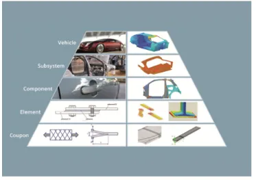
Figure 1. The pyramid of tests: physical and predictive virtual prototypes
Although different modeling and analysis approaches exist in the literature and in commercial software [1-6], the cohesive element formulation and the associated damage model available in the LMS Samtech Samcef finite element code for modeling delamination of laminated composites are here considered [7]. The approach is based on continuum damage mechanics and was initially developed by the Ladevèze’s team in Cachan [8]. The damage model is assigned to interface elements inserted between the plies to represent their possible de-cohesion and inter-laminar crack propagation can be simulated. This damage model is first presented. The basics of the parameter identification procedure are briefly explained. Test results at the coupon level on double cantilever beam (DCB) and end notched flexure (ENF) specimens are used to identify the parameters of the damage law. The obtained values are then validated on a mixed mode bending (MMB) test.
Even if lots of models are available in the literature [9-14], the formulation developed in LMS Samtech Samcef for modeling the damages inside the plies (intra-laminar damages) is based on the continuum damage mechanics approach initially developed in [15], in which the laminate is made of homogenous plies and damage variables impacting the stiffness of each ply are associated to the different failure modes, representing the fiber breaking, matrix cracking and de-cohesion between fibers and matrix. The advantage of this damage model compared to some others is that a parameter identification procedure can be developed. Moreover, the model is native in LMS Samtech Samcef and there is no need for additional (not free) plug-ins to solve the progressive damage problem.
Once the value of their parameters are identified at the coupon level, the inter- and intra-laminar damage models are used in finite element models at the upper stages of the pyramid of tests (building block approach, Figure 1) to study more complicated structures: in this paper, L-shaped beams and impacted plates. Comparisons between tests and simulations demonstrate the reliability of the numerical solution.
INTRA-LAMINAR DAMAGE MODEL
The intra-laminar damage model for the unidirectional ply is described in detail in reference [15]. It is based on the continuum damage mechanics. In this approach, damage variables taking their values between 0 and 1 are introduced in the formulation to penalize the material stiffness.
The model is described by 23 parameters (to be identified). It includes the 9 elastic orthotropic properties in 3D (E01, E02, E03,
ν
12,ν
23,ν
13, G012, G013, G023) and specificparameters associated to damage and plasticity (like Y11s, Y012, Ys12, R0,
β
and n inFigures 2 and 3). The potential ed in (1), written here in plane stress for the
homogeneous ply, includes the damage variables d11, d22 and d12 related to the fibers,
the transverse and the shear directions, respectively. The damage in the transverse direction only appears in tension, not in compression, as cracks get closed in the matrix under a compressive loading.
0 12 12 2 12 0 2 2 22 0 2 22 2 22 22 11 0 1 0 12 0 1 11 2 11 ) 1 ( 2 2 ) 1 ( 2 ) 1 ( 2 d E E d E E d G ed − + + − − − − = σ ν σ σ σ + σ − σ (1)
The so-called thermodynamic forces Yi (see reference [15]) are the derivatives of
the potential ed with respect to the damage variables di. They can be seen as the
loading in the different directions. They manage the evolution of the damages as illustrated in Figure 2a and 2c. In the fiber direction (Figure 2a), the behavior is brittle, and the damage increases suddenly from 0 to 1 when the material strength, expressed in terms of √Y11, is reached. In the matrix, the damage produces a decrease of the material stiffness (Figure 2b), and its evolution with respect to the loading (here √Y12) is more complex (Figure 2c). The two damages in the matrix, d12 and d22, are coupled.
Figure 2. Damages in the fiber direction (a) and in the matrix (b,c)
Besides damage, non-linearity is also taken into account in the fiber direction (Figure 3a). For the matrix, inelastic effects are considered in the form of a plastic law, which captures the permanent deformations (Figures 2 and 3). These material behaviors come from interpretation of tests.
Figure 3. Non linearity in the model
INTER-LAMINAR DAMAGE MODEL
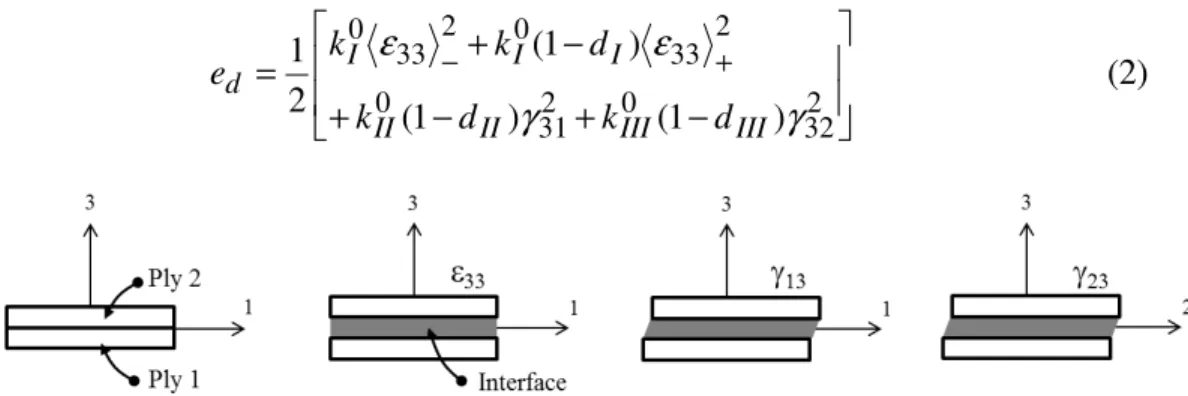
The inter-laminar damage model for delamination is based on the cohesive elements approach [7,8]. A potential is assigned to the interface elements, and three damage variables di are related to modes I, II and III (opening, sliding and tearing
modes, respectively). − + − + − + = − + 2 32 0 2 31 0 2 33 0 2 33 0 ) 1 ( ) 1 ( ) 1 ( 2 1
γ
γ
ε
ε
III III II II I I I d d k d k d k k e (2)Figure 4. Interface and components of the stress tensor
ki0 in (2) is the undamaged stiffness. Thermodynamic forces Yi are obtained by
deriving (2) with respect to di. For mixed mode loading, the damage evolution is
related to the inter-laminar fracture toughness (GIC, GIIC and GIIIC) in an equivalent
thermodynamic force Y taking the following form:
α α α α τ / 1 sup + + = ≤ IIIC III IIC II IC I IC t G Y G Y G Y G Y (3)
In (3), α is a coupling coefficient, and t represents the time (pseudo-time when static analysis is addressed). The sup symbol in (3) means that the thermodynamic force can’t decrease over time, so reflecting that damage is irreversible. In the model, the three damage variables have the same evolution over the loading and a unique damage d is therefore defined. The damage is related to Y via a function g(Y). Three different functions g(Y) are available leading to polynomial, bi-triangular and exponential cohesive laws, as illustrated in Figure 5, respectively.
Figure 5. Damage laws for the cohesive elements
PARAMETER IDENTIFICATION PROCEDURE
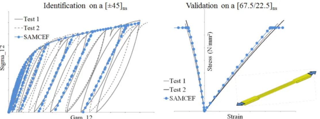
From the coupon testing performed on classical machines according to some standards (e.g. ASTM D3039, www.astm.org), the longitudinal stress σL and the axial and transversal strains εL and εT are obtained. Based on this information at the coupon level, the 23 parameters of the ply model are determined. In practice, four series of tests are conducted, each series on a specific (well-defined) stacking sequence and/or loading scenario. As typically 5 successful tests are usually required, it results that 20 (= 4 x 5) successful tests must be conducted to cover the 4 series, that is a total of 20 tested coupons. This is enough to identify the 23 parameters of the progressive damage ply model, i.e. the damage, plastic and initial elastic properties. The identification procedure is done without extensive use of simulation. It is a simple procedure based on EXCEL sheets, which can be sped up by some very simple programming. A comparison between an ASTM D3039 test and simulation is used to validate the identified values on a stacking sequence not used for the identification (Figure 6).
Figure 6. Comparison between test and simulation for the identification and validation at the coupon level (intra-laminar damage model)
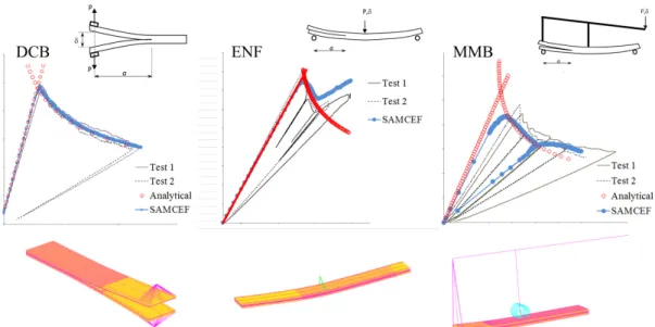
For the cohesive laws, specific DCB, ENF and MMB tests (www.astm.org) are performed. Finite element models are developed and a fitting between experiments and numerical results is conducted (Figure 7) to get the value of the parameters. Analytical solutions based on beam theory are also used to fine tune these values.
Figure 7. Comparison between test and simulation for the identification of the inter-laminar damage model parameters at the coupon level (delamination)
APPLICATIONS AT THE UPPER STAGES OF THE PYRAMID
The parameters of the inter- and intra-laminar damage models identified at the coupon level as explained in the previous sections are now used in simulations at the upper stages of the pyramid of Figure 1.
The numerical tests are conducted with the LMS Samtech Samcef implicit finite element code. Solid shell finite elements with EAS and ANS formulations are used. The element height is equal to the ply thickness. Interface elements are defined between each ply. Mesh sensitivity studies were conducted in order to work with a converged mesh.
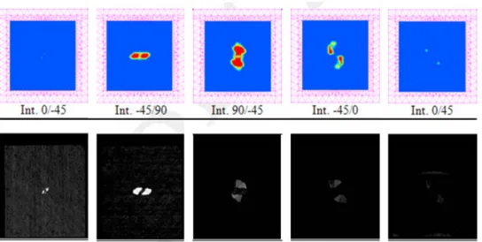
In a first application, a [45/0/-45/90]s plate is submitted to an impact. Test results are obtained with a C-scan and are illustrated by the second line of Figure 8: the white spots correspond to the detected damages. The simulation determines the amount of damage in each interface, with the following code of colors: red means completely broken (d = 1) while blue corresponds to no local damage (d = 0). The damaged interfaces are illustrated in the first line of Figure 8. It is clear that the agreement between the test results and the simulation is very good.
In the second application, an L-shaped beam submitted to two different load cases and boundary conditions is considered (Figure 9). The laminates are made up of 12 plies with the following stacking sequence [60/-60/0/0/-60/60]s.
Figure 8. Results of the impact on the laminated plate
Even if ply damage is present, the failure is mainly driven by delamination leading to large sliding of the plies. In Figure 10, a comparison between tests and simulations is done. The global behaviors are very similar. In Figure 11, the load-displacement curves show that a very good agreement is obtained between test and simulation.
Figure 9. Two configurations for the L-shaped beam
Figure 11. Load-displacement curves
FATIGUE ANALYSIS OF LAMINATED COMPOSITES
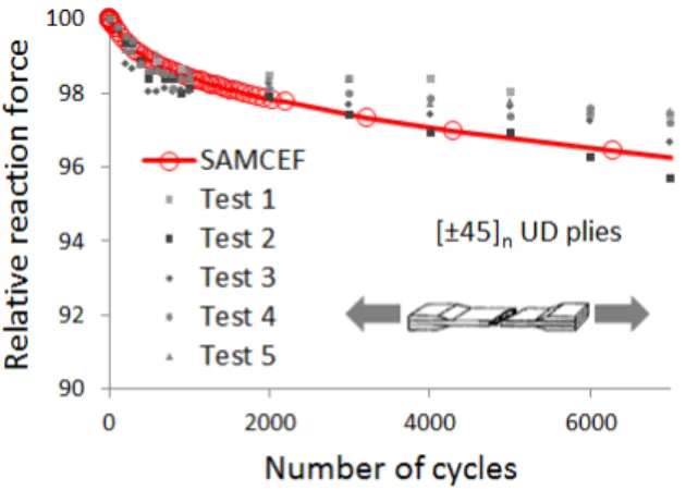
Besides the static case described in the previous sections, fatigue is another interesting attribute to consider for the sizing of composite structures. Even if it’s known that laminated composites have a good behavior in fatigue, it is anyway interesting to study, for instance, the degradation occurring during the first fatigue cycles. Indeed, as illustrated in Figure 12, a significant decrease of the stiffness properties, associated to damage via a relation E=E0(1-d) in the continuum damage
mechanics approach, is observed in testing [18]. In Figure 12, the resultant force of the beam submitted to fatigue bending is recorded: it decreases over the cycles, demonstrating that damage appears in the composite.
Figure 12. Intra-laminar fatigue analysis with SAMCEF of a balanced woven fabric laminate [45]n (from [18])
The fatigue framework available in the SAMCEF finite element code for intra-laminar damage was adapted here in order to study laminates made up of unidirectional plies. It is based on the cycle jump approach proposed in [18] and is illustrated in Figure 13.
Figure 13. Principle of the cycle jump algorithm implemented in SAMCEF (from [18])
First, a static cycle is run in order to get a relevant stress history. This information is then provided to the specific fatigue law with damage accumulation, which is used to determine the variation in the number of cycles ∆Ni at each computational point i for a given variation of the damage amplitude ∆d assigned to the structure. A statistical treatment is then conducted, in order to determine the unique ∆N to apply to all the computational points. Finally, knowing this value, the related ∆di deduced from the fatigue law are then applied to adapt the local values of the material stiffness, as Ei=Ei0(1-di). In the developed formulation, the cyclic loading is limited to constant amplitude during each cycle jump phase. With the specific fatigue law ∂d/∂N and the cycle jump strategy, the computation of each cycle is avoided, what is interesting for saving computational time. In Figures 14 and 15 are reported first comparisons between physical tests and simulations obtained with SAMCEF, for intra-laminar fatigue damage appearing after a few cycles in coupons made up of plies oriented at either 0° or ±45°, and submitted to in-plane loading.
Figure 14. Damage occurring during the first fatigue cycles, in a laminate made of UD plies oriented at 0°
Figure 15. Damage occurring during the first fatigue cycles, in a laminate made of UD plies oriented at ±45°
CONCLUSION
In this paper the solution available in the LMS Samtech Samcef finite element code for the damage analysis of laminated composite structures was presented. Inter- and intra-laminar damage models and their parameter identification procedure were described. Comparisons between tests and simulations were done at different stages of the pyramid for static structural sizing. First results obtained for fatigue analysis at the coupon level were also presented.
REFERENCES
1. Camanho, P.P. Finite element modeling of fracture in composites: current status and future developments. 2006. NAFEMS Seminar – Prediction and Modeling of Failure Using FEA. NAFEMS, Roskilde, Denmark.
2. Krüeger, R. 2004. Virtual Crack Closure technique: history, approach and applications. Applied Mechanics Reviews 57: 109-143.
3. Krüeger, R. 1994. Three dimensional finite element analysis of multidirectional composite DCB, SLB and ENF specimens, ISD-Report N° 94/2, Institute for Statics and Dynamics of Aerospace Structures, University of Stuttgart.
4. Orifici, A.C., Thomson, R.S., Degenhardt, R., Bisagni, C., and Bayandor, J. 2007. Development of a finite element analysis methodology for the propagation of delaminations in composite structures. Mechanics of Composite Materials 43: 9-28.
5. Xie, D. and Bigger, S.B. 2006. Progressive crack growth analysis using interface element based on the Virtual Crack Closure Technique. Finite Elements in Analysis and Design 42: 977-984. 6. Krüeger, R. 2007. An approach for assessing delamination propagation capabilities in
commercial finite element codes, American Society of Composites 22nd Annual Technical Conference, University of Washington, Seattle, WA, September 17-19.
7. Bruyneel, M., Delsemme, J.P., Jetteur, P. and Germain, F. 2009. Modeling inter-laminar failure in composite structures: illustration on an industrial case study. Applied Composite Materials
16: 149-162.
8. Allix, O. and Ladevèze, P. 1992. Interlaminar interface modelling for the prediction of laminate delamination, Composite Structures 22: 235-242.
9. Nuismer, R.J. and Tan, S.C. 1988. Constitutive relations of a cracked composite lamina. J. Compos. Mater. 22: 306–21.
10. Tan, S.C. and Nuismer, R.J. 1989. A theory for progressive matrix cracking in composite laminates. J. Compos. Mater. 23: 1029–47.
11. Li, S., Reid, S.R. and Soden P.D. 1998. A continuum damage model for transverse matrix cracking in laminated fibre-reinforced composites. Philos Trans R Soc Lond Ser A (Math Phys Eng Sci) 356: 2379–412.
12. Adolfsson, E and Gudmundson, P. 1999. Matrix crack initiation and progression in composite laminates subjected to bending and extension. Int. J. Solids Struct. 36: 3131–69.
13. Katerelos, D.T.G., Varna, J. and Galiotis C. 2008. Energy criterion for modeling damage evolution in cross-ply composite laminates. Compos Sci Technol 68: 2318–24.
14. Mayugo, J.A., Camanho, P.P., Maimi, P. and Dávila, C.G. 2010. Analytical modeling of transverse matrix cracking of [±h/90n] composite laminates under multiaxial loading. Mech Adv Mater Struct 17: 237–45.
15. Ladeveze, P. and Le Dantec, S. 1992. Damage modeling of the elementary ply for laminated composites, Composites Science and Technology 43: 123-134.
16. Allix, O. 2007. The damage meso-model for laminates – interface identification and application to delamination. Course on Emerging Techniques for Damage Prediction and Failure Analysis of Laminated Composite Structures, Cépaduès Editions.
17. Bruyneel, M., Delsemme, J.P., Goupil, A.C., Jetteur, P., Lequesne, C., Naito, T. and Urushiyama, Y. 2014. Damage modeling of laminated composites: validation of the intra-laminar damage law of SAMCEF at the coupon level for UD plies, European Conference on Composite Material, ECCM16, Sevilla, Spain, 22-26 June 2014.
18. Van Paepeghem W. 2002. Development and finite element implementation of a damage model for fatigue of fibre-reinforced polymers. PhD Thesis, University of Ghent, Belgium.

![Figure 12. Intra-laminar fatigue analysis with SAMCEF of a balanced woven fabric laminate [45] n (from [18])](https://thumb-eu.123doks.com/thumbv2/123doknet/6555939.176941/9.918.177.700.631.803/figure-intra-laminar-fatigue-analysis-samcef-balanced-laminate.webp)
![Figure 13. Principle of the cycle jump algorithm implemented in SAMCEF (from [18])](https://thumb-eu.123doks.com/thumbv2/123doknet/6555939.176941/10.918.195.749.81.434/figure-principle-cycle-jump-algorithm-implemented-samcef.webp)