En vue de l'obtention du
DOCTORAT DE L'UNIVERSITÉ DE TOULOUSE
Délivré par :
Institut National Polytechnique de Toulouse (INP Toulouse)
Discipline ou spécialité :
Génie des Procédés et de l'Environnement
Présentée et soutenue par :
M. TRUNG DUNG NGUYEN
le mercredi 14 janvier 2015
Titre :
Unité de recherche :
Ecole doctorale :
CONCEPTUAL DESIGN, SIMULATION AND EXPERIMENTAL
VALIDATION OF DIVIDED WALL COLUMN: APPLICATION FOR
NON-REACTIVE AND NON-REACTIVE MIXTURE
Mécanique, Energétique, Génie civil, Procédés (MEGeP)
Laboratoire de Génie Chimique (L.G.C.)
Directeur(s) de Thèse :
M. MICHEL MEYER MME XUAN MI MEYER
Rapporteurs :
M. JEAN-MICHEL RENEAUME, UNIVERSITE DE PAU ET DES PAYS DE L ADOUR M. LIONEL ESTEL, INSA ROUEN
Membre(s) du jury :
1 M. VINCENT GERBAUD, INP TOULOUSE, Président
2 M. DAVID ROUZINEAU, INP TOULOUSE, Membre
2 M. MATHIAS BREHELIN, SOLVAY LYON, Membre
2 Mme XUAN MI MEYER, INP TOULOUSE, Membre
2 M. MICHEL MEYER, INP TOULOUSE, Membre
“I dedicated to the enduring memory of my father and to my beloved mother.
I delicate to my loving family, my wife NHU Thi Thu Hang, my daughter NGUYEN Ha An,
Acknowledgements
I would like to express my sincere gratitude to my supervisor Prof. Michel MEYER for his guidance during the course of this research. I am grateful for his encouragement and giving me an opportunity to use all the facilities available in the department for my research work.
I wish to express my sincere appreciation to Dr. David ROUZINEAU for his suggestions and practical experience during my research.
I am thankful to all the staff members of the department, laboratory, and secretaries for providing a friendly and stimulating environment.
I am very grateful to the Vietnam ministry of education for the financial support during the course of this Ph.D. study.
I would like to express my thanks to all my friends.
I would also like to express my gratitude to my mother for her enormous love, support and sacrifice.
Last but not least, I special thank to my wife and children for their love, understanding during my study.
ABSTRACT
Divided wall column and reactive distillation have many advantages. If a divided wall column and a reactive distillation are integrated, they leads to a higher integrated process is a reactive divided wall column. However reactive divided wall column has still a new research area. First of all, the thesis proposed a procedure for design of divided wall column, which based on the FUGK model. Both technological and hydrodynamic aspects in the divided wall column are considered in the procedure. Design parameters are then provided to the rigorous simulation and optimization in the ProSimplus software. In order to test this procedure, both ideal and non-ideal ternary mixtures are chosen to be separated in a divided wall column. The results show that the procedure can determine parameters quickly in the case studies and can give a good initialization for rigorous simulation. Secondly, a pilot plant has been design, built and operated in our laboratory (LGC, Toulouse, France, 2013). The pilot plant will provide necessary experimental evidence to validate the previous procedure. Ternary mixture and four-component mixture of alcohols have been used in our pilot plant in steady state conditions. The results show that the composition of products, composition and temperature profile along the column are in very good agreement with simulation results. Finally, a conceptual design method for reactive divided wall column is presented. The pre-design method of R. Thery et al., (2005) and a modified shortcut method for reactive divided wall column that is based on the classical shortcut adapted to a non-reactive divided wall column by C. Triantafyllou and R. Smith (1992) are applied. To verify, simulation and experiment are considered. The methodology has been illustrated for the synthesis of Methyl Acetate from Methanol and Acetic Acid.
Key words: Design, Simulation, Experiment, Divided wall column, Reactive divided wall
RESUME
Les colonnes à cloison et la distillation réactive présentent de nombreux avantages. Si ces deux concepts sont couplés, cela conduit à un procédé intensifié appelé : colonne à cloison réactive. Ce nouveau procédé intensifié constitue le principal objet d’étude de cette thèse. Dans une première partie, une procédure de design d’une colonne à cloison basée sur le modèle FUGK a été proposée. Dans cette procédure les aspects technologiques et hydrodynamiques sont abordés. Ces paramètres de design obtenus sont ensuite utilisés pour réaliser une simulation rigoureuse et une optimisation de cette colonne en utilisant le logiciel ProSim. Afin de tester cette procédure, des mélanges idéaux et non idéaux ont été utilisés. Il a été montré que cette procédure de design aboutit rapidement aux paramètres de pré design qui permettent d’initialiser de manière satisfaisante la simulation rigoureuse. Dans un second temps, un pilote d’une hauteur de 4m a été conçu, monté et testé au laboratoire. Des résultats expérimentaux ont été obtenus qui valident la procédure sur des mélanges non réactifs en termes de profils de composition et de température ainsi que sur les compositions et les débits de sortie du procédé. Enfin, dans une dernière partie, cette procédure a été adaptée à des mélanges réactifs en combinant les approches de R. Thery et al (2005) et celle de Triantafyllou et al (1992). Ces ultimes développements ont été testés sur la production d’acétate de méthyl par estérification du méthanol par l’acide acétique à la fois d’un de vue expérimental et théorique.
TABLE OF CONTENTS
ABSTRACTCHAPTER 1 INTRODUCTION
1.1 PROCESS INTESIFICATION
1.2 MOTIVATION AND AIM OF THE WORK 1.3 OUTLINE OF THE THESIS
1.4 PUBLICATION LIST CHAPTER 2
LITERATURE REVIEW
2.1 DIVIDED WALL COLUMN FUNDAMENTALS 2.1.1 Concept of divided wall columns
2.1.2 Advantages and disadvantages of divided wall columns 2.1.3 Divided wall column configurations
2.1.4 Divided wall column design parameters 2.1.5 Control of divided wall columns 2.1.6 Simulation of divided wall columns 2.1.7 Divided wall column applications
2.2 CONCEPTUAL DESIGN OF A DIVIDED WALL COLUMN: REVIEW
2.3 CONCEPTUAL DESIGN OF A REACTIVE DIVIDED WALL COLUMN: REVIEW
2.4 CONCLUSION OF CHAPTER 2 CHAPTER 3
DESIGN METHODOLOGY OF DIVIDED WALL COLUMN 3.1 A PROCEDURE FOR DESIGN OF DIVIDED WALL COLUMNS
3.1.1 Assumptions and model design
3.1.2 Material balance for divided wall columns
1 2 4 5 5 6 7 10 11 13 14 15 19 20 23 28 34 35 36 36 39
3.1.3 Minimum vapor flowrate of divided wall columns 3.1.4 Technological and hydrodynamic aspects
3.2 SIMULATION WITH PROSIMPLUS SOFTWARE 3.2.1 The model used for simulation
3.2.2 Initial parameters for simulation 3.3 CASE STUDIES
3.3.1 Separation of a ternary mixture
3.3.2 Separation of a mixture with more than three components 3.3.3 Conclusion
3.4 SENSIBILITY ANALYSIS OF DIVIDED WALL COLUMN 3.4.1 Effect of the vertical position and height of the wall 3.4.2 Effect of the number of stages
3.4.3 Effect of the feed composition and ESI of the mixture on the design of divided wall columns
3.4.4 Energy usage comparison between traditional columns and divided wall columns
3.5 CONCLUSION CHAPTER 4
PILOT PLANT AND EXPERIMENTAL VERIFICATION: APPLICATION FOR NON-REACTIVE MIXTURE
4.1 INTRODUCTION 4.2 PILOT PLANT
4.2.1 Setup
4.2.2 Measurement and startup of the pilot plant 4.2.3 HETP experiment 4.2.4 Component systems 40 44 49 49 50 52 52 55 57 58 58 59 60 62 67 68 69 73 73 75 76 77
4.3 EXPERIMENTAL RESULTS
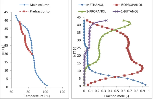
4.3.1 Separation of ternary mixture: methanol/1-propanol/1-butanol
4.3.2 Separation of four - component mixture: methanol/iso propanol/1-propanol/1-butanol
4.4 COMPARISON BETWEEN EXPERIMENTAL DATA AND SIMULATED RESULTS
4.4.1 Ternary mixture
4.4.2 Four-component mixture 4.5 CONCLUSION OF CHAPTER 4 CHAPTER 5
DESIGN OF REACTIVE DIVIDED WALL COLUMN 5.1 INTRODUCTION
5.2 PROCEDURE FOR DESIGN OF REACTIVE DIVIDED WALL COLUMNS 5.2.1 Model and assumptions for a reactive divided wall column
5.2.2 Classification of feed composition region by predesign method 5.2.3 Modified shortcut design method for reactive divided wall column 5.2.4 Simulation
5.3 CASE STUDY FOR METHYL ACETATE SYNTHESIS 5.4.1 Introduction
5.4.2 Kinetic and equilibrium equations and thermodynamic model 5.4.3 Design Procedure
5.4.4 Conclusion
5.5 EXPERIMENTAL VERIFICATION FOR A REACTIVE MIXTURE IN A DIVIDED WALL COLUMN
5.5.1 Introduction 5.5.2 Experiment results 77 77 82 85 87 92 94 95 96 97 97 100 101 104 105 105 106 106 115 116 116 117
5.6 CONCLUSION OF THE CHAPTER 5 CHAPTER 6
GENERAL CONCLUTIONS AND FUTURE WORK 6.1 THE MAIN CONTRIBUTIONS OF THE THESIS 6.2 PERSPECTIVES APPENDIX Appendix 1 Appendix 2 Appendix 3 Appendix 4 Appendix 5 Appendix 6 Appendix 7 Appendix 8 NOMENCLATURE REFERENCES 120 121 122 124 126 127 128 130 131 143 144 145 149 150 153
LIST OF FIGURES
FIGURE 2.1 Conventional arrangements for separating three component mixtures FIGURE 2.2 Fully thermally coupled distillation column (Petlyuk column) FIGURE 2.3 Heat integrate distillation column (HIDiC)
FIGURE 2.4 Divided wall column
FIGURE 2.5 Separation for ternary mixture in the divided wall column
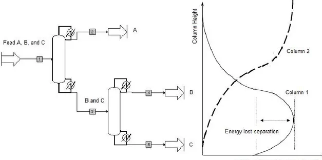
FIGURE 2.6 Energy is lost separating the middle component B in the conventional arrangement
FIGURE 2.7 Basic types of divided wall column: (a) Divided wall column middle, (b) Divided wall column lower, (c) Divided wall column upper
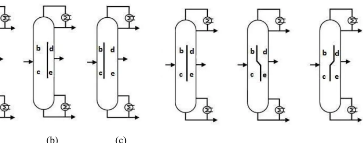
FIGURE 2.8 Different position of dividing wall FIGURE 2.9 Different sharp of dividing wall
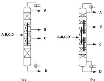
FIGURE 2.10 Divided wall column for separation of four-component mixture (a) Kaibel column and (b) column with multiple partition walls FIGURE 2.11 DWC design parameters
FIGURE 2.12 Controller in the Petlyuk column (E.A.Wolff and Skogestad (1995)) FIGURE 2.13 PI controller for a divided wall column (Till Adrian et al., (2004)) FIGURE 2.14 Control structures of divided wall column (Buck et at., (2011)) FIGURE 2.15 Schematic and photograph of the two vapor split valves (Dwivedi D et al., (2012))
FIGURE 2.16 Pump around model of divided wall column
FIGURE 2.17 Two columns sequence model (prefractionator or side column) FIGURE 2.18 Four columns sequence model
FIGURE 2.19 Decomposition into simple column sequences (grey area: reactive zone) (Mueller, I et al. (2007))
FIGURE 3.1 (a) Divided wall Column; (b) Thermally coupled distillation FIGURE 3.2 Simplified model design of divided wall column
FIGURE 3.4 Types and positions of dividing wall in the DWC system FIGURE 3.5 A procedure for design of divided wall column
FIGURE 3.6 The model for simulation DWC system by ProSimplus software FIGURE 3.7 Initial parameters need for simulation by ProSim plus
FIGURE 3.8 Design parameters for the divided wall column FIGURE 3.9 Design parameters for the divided wall column
FIGURE 3.10 Specify variables for four-composition mixture in divided wall column
FIGURE 3.11 Design parameters for the divided wall column
FIGURE 3.12 Temperature and composition profiles in the divided wall column FIGURE 3.15 Effect of the height and vertical position of the wall on the heat duty of reboiler
FIGURE 3.16 Effect of number of stages on heat duty of reboiler
FIGURE 3.17 Heat duty depend on the feed composition and ESI index of the mixture
FIGURE 3.18 1000TAC depend on the feed composition and ESI index of the mixture
FIGURE 3.19 Energy duty comparison of the mixture M1 (ESI = 1) FIGURE 3.20 Energy duty comparison of the mixture M2 (ESI > 1) FIGURE 3.21 Energy duty comparison of the mixture M3 (ESI < 1) FIGURE 3.32 Comparison energy of use and boundary of distillation FIGURE 4.1 Flow-sheet of the pilot plant
FIGURE 4.2 Liquid splitter
FIGURE 4.3 Structure parameters of pilot plant
FIGURE 4.4 Experimental temperature profiles for case 1, case 2, case 3, and case 4
FIGURE 4.5 Composition profiles of experimental runs
FIGURE 4.6 Experimental temperature and composition profiles for case 5 and case 6
FIGURE 4.7 Step-to-step to adjust variables for simulation process
FIGURE 4.8 Temperature and composition profile of experimental data and simulation results for case studies
FIGURE 4.9 Difference temperature between the prefractionator and the main column depended on the feed composition
FIGURE 4.10 Vapor split (RV) depends on the liquid split (RL)
FIGURE 4.11 Temperature and composition profile compare between the experimental data and simulation of case 5 and case 6
FIGURE 5.1 Processes integration of reactive distillation and divided wall column FIGURE 5.2 Restriction of the model for reactive divided wall column
TABLE 1.1 Process intensification technologies in the petrochemical industry
(Harmsen, 2010)
TABLE 2.1 Industrial applications of DWCs for ternary systems (Yildirim et al.,
2011)
TABLE 2.2 Industrial applications of divided wall column for multicomponent
mixtures
TABLE 2.3 Summary of several shortcut methods for design divided wall
column
TABLE 2.4 Works published for reactive divided wall column TABLE 3.1 Twelve unknown variables for ternary mixture separation TABLE 3.2 Relationship between feed quality and internal flowrates
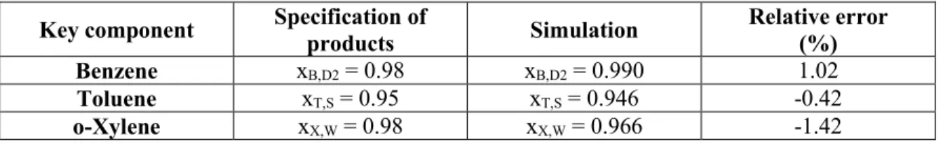
TABLE 3.3 Relative errors between specify product purity and simulation of key
component
TABLE 3.4 Relative errors between specify product purity and simulation of key
component
TABLE 3.5 Relative errors between specify product purity and simulation of key
component
TABLE 3.6 Three ternary mixtures
TABLE 3.7 Three different feed compositions
TABLE 3.8 Energy consumption and TAC of the divided wall column TABLE 3.9 Four different feed compositions
TABLE 3.10 Energy duties of the arrangements
TABLE 3.11 Comparing the results with guess of the Kiss et al., (2012) TABLE 4.1 Overview of various DWC or RDWC pilot plants
TABLE 4.2 Operating parameters and results for experimental steady-state runs TABLE 4.3 Operating parameters and results for experimental steady-state runs TABLE 4.4 Least square error and relative error of key component
TABLE 4.5 Detail comparisons between experimental data and simulated result
of case 1
TABLE 5.1 Ranking of azeotropes temperature and pure component normal
boiling point temperature
TABLE 5.2 Classification of feed composition for direct separation
TABLE 5.3 Relative errors between simulation and specification of key
component (Case 1)
TABLE 5.4 Corrected the composition of the distillate product
TABLE 5.5 Relative errors between simulation and specification of key
component (case 2)
TABLE 5.6 Mass balance of total and each component
TABLE 5.7 Experimental results at steady-state run compare with simulation
Chapter 1: Introduction
Chapter 1
Chapter 1: Introduction
2
1.1 PROCESS INTENSIFICATION
Nowadays, because of environmental problems and the energy crisis, both industrial and academic research efforts aim to develop process design methodologies for reducing the energy usage, waste and impact of chemical processes on the environment. If only considering process-related energy for the manufacture of products from feed stocks, the total global energy consumption of the chemical and petrochemical industry is estimated at 15 Ejyr-1 and the world total GHG emissions attributed to chemical and petrochemical processes amounts to 1.24 GtCO2-eq annually (IEA, 2013).
Process integration is a method to process design and operation that emphasizes the unity of the process. From an Expert Meeting in Berlin, October 1993, the IEA (International Energy Agency) definition of process integration is:
“Systematic and general methods for designing integrated
production systems, ranging from individual processes to total sites, with special emphasis on the efficient use of energy and
reducing environmental effects”.
One of the most significant examples of process integration is process intensification. It is a process in which multiple phenomena such as reaction, separation and heat transfer are integrated in one single equipment. This process is attracting more and more attention. The first definition of process intensification is offered by Cross and Ramshaw (1986):
“Process intensification is a term used to describe the strategy of
reducing the size of chemical plant needed to achieve a given
production objective”.
In 2000, Andrzej I. Stankiewicz and Jacob A. Moulijn proposed a more particular definition:
“Any chemical engineering development that leads to a
substantially smaller, cleaner and more energy efficient technology is process intensification”.
The objectives in this definition are smaller, cleaner, and more energy efficient technology. According to David Reay, Colin Ramshaw and Adam Harvey (2013), they added a new objective, “safer”, to the definition:
“Any chemical engineering development that leads to a
substantially smaller, cleaner, and safer and more energy efficient technology is process intensification”.
Chapter 1: Introduction
The main advantages of process intensification are: Cheaper processes;
Smaller equipment and plant; Safer processes;
Reduced energy consumption; Shorter time to the market; Less waste or by product; Better company image.
Process intensification includes (1) process – intensifying equipment such as novel reactors, and intensive mixing, heat transfer and mass transfer devices and (2) process – intensifying
methods such as new or hybrid separations and multifunctional reactors.
Nowadays, process intensification technology has potential to development the chemical industry and is one of the most significant trends in chemical engineering. Both divided wall columns and reactive distillation are excellent examples of process intensification methods. They are both improvements of traditional distillation units but at the same time they correspond to two different ways of integration: Divided wall columns are a combination of two separations while reactive distillation is combined reaction and separation in a single unit (Mueller and Kenig, 2007). In the petrol-chemical industry, process intensification technology has been applied more than 150 times with reactive distillation and more than 100 times with divided wall columns (Harmsen, 2010) as shown in Table 1.1.
TABLE 1.1 Process intensification technologies in the petrochemical industry (Harmsen,
2010)
Technologies Capital cost reduction Energy reduction implementation Commercial
Reactive distillation 20 – 80% 20 – 80% > 150
Chapter 1: Introduction
4
1.2 MOTIVATION AND AIM OF THE WORK
The concept of divided wall columns has been known for a long time as having a large potential for savings in both energy and investment costs proven by process applications and academic studies. The concept of reactive distillation has also been applied with many advantages such as overcoming of chemical equilibrium limitations, achievement of higher selectivity and use of reaction heat in separation process, (Kai Sundmacher and Achim Kienle, 2002).
The integration of divided wall columns and reactive distillation leads to a better integrated process is a reactive divided wall column. It is noted that reactive divided wall columns is still a new research area (Guido Daniel, 2006). Therefore:
“The motivation of this study will focus on the conceptual design, simulation, and experiment for reactive divided wall column”.
In order to achieve this objective, in the study, we focus on:
For the divided wall column, a large number of publications have been written on this equipment, Z. Olujic et al (2009), I. Dejanovic et al (2010), and Omer Yildirim et al (2011). However, a comprehensive review covering all aspects of optimal design, analysis, simulation, and experimental data of divided wall column is still missing. Moreover, we need to develop a simulation model for divided wall columns carried out in ProSimplus software. Therefore, firstly, an approach to optimal design, simulation model in ProSimplus software, and experimental runs with non-reactive mixtures are considered.
For reactive distillation, a methodology to design the reactive distillation column developed by Thery et al (2007) will be applied.
Based on the shortcut method to design divided wall columns and the method of design for reactive distillation developed by Thery et al (2007), a proposed method to design reactive divided wall column is proposed. After that, experimental runs for reactive mixtures are verified.
Chapter 1: Introduction 1.3 OUTLINE OF THE THESIS
The thesis is divided into 6 chapters: Chapter 1 gives the introduction, motivation and aim of this work, and outline of the thesis. Chapter 2 is a literature review concerning publications on divided wall columns and reactive divided wall columns. Chapter 3 focuses on the development of a procedure for optimal design of divided wall columns. Then, the shortcut results will be introduced into ProSimplus to carry out simulations. The analysis of divided wall column performance is also considered. Chapter 4 shows the pilot plant for the divided wall column in our laboratory in which the structure of pilot plant and experimental results are presented. Non-reactive mixtures were tested in the pilot plant. The focus of Chapter 5 is the design of a reactive divided wall column. Then, an experimental run for reactive mixtures was carried out in reactive divided wall column.
1.4 PUBLICATION LIST
NGUYEN Trung-Dung, David ROUZINEAU, Michel MEYER, and Xuan MEYER. (2013). A new procedure for design of divided wall column, ECCE9|ECAB2, April 21-25, The Hague, The Netherlands.
NGUYEN Trung-Dung, David ROUZINEAU, Michel MEYER, and Xuan MEYER. (2013). A new Procedure for optimal design of divided wall column, SFGP 2013, 8 – 10 Octobre, Lyon, France.
NGUYEN Trung-Dung, David ROUZINEAU, Michel MEYER, and Xuan MEYER. (2014). Is divided wall column always better than traditional distillation column?, GPE – 4th
International Congress on Green Process Engineering, 7 – 10 April, Sevilla, Spain.
NGUYEN Trung-Dung, David ROUZINEAU, Michel MEYER, and Xuan MEYER. (2014). Conceptual design, simulation, and experiment for a reactive divided wall column, 10th
International conference on Distillation and Absorption, 14 – 17 September, Friedrichshafen,
Chapter 2: Literature review
6
Chapter 2
Chapter 2: Literature review 2.1 DIVIDED WALL COLUMN FUNDAMENTALS
The chemical and petrochemical sectors are the largest industrial energy users, accounting for roughly 10% of total worldwide energy demand and 7% of global GHG emissions. In the chemical process industry, approximately 40% of total energy is used by distillation processes (Dejanovic, 2011). In the distillation technique, heat is used as a separating agent. Heat is supplied to the bottom reboiler to evaporate a liquid mixture at high temperature and is lost at low temperature when liquefying in the condenser at the top of the distillation column. Therefore it is highly inefficient in the use of energy.
With the beginning of the oil crises of the 1970s and 1980s, the energy costs became the major factor in column costs and created an urgency to find ways to reduce the energy requirements of distillation. Therefore, a primary target in new distillation process designs is how to reduce the energy demand of distillation systems. Various methods can be used to make the distillation process more energy efficient and more sustainable such as thermally coupled distillation columns (Petlyuk column), heat integrated distillation columns (HIDic), and divided wall columns (DWC).
To separate a multicomponent mixture, one often uses a sequence of distillation columns. We consider separation of a ternary mixture A, B, and C, for instance, Figure 2.1 shows the typical arrangements (direct, indirect and sloppy sequence) that use at least two columns, two reboilers and two condensers to produce three pure products.
The three components of the mixture are A, B and C, in which A is the light boiling component, B is the middle boiling component and C is the heavy boiling component. In the direct configuration, figure 2.1 (a), the component A will be separated in the first column and B and C will be separated in the second column. In the indirect configuration, figure 2.1(b), the component C will be separated in the first column with A and B being separated in the second column. In the sloppy sequence, figure 2.1 (c), the component B is a distributed component. That means, in the first column, A and C will be separated and B is distributed. The second column separates the A and B components. The third column separates the B and C components.
Chapter 2: Literature review
8
(a) (b)
(c)
FIGURE 2.1 Conventional arrangements for separating three component mixtures
((a) Direct, (b) indirect and (c) sloppy sequences)
A thermally coupled distillation column was first patented by Brugma, 1942. For ternary mixture separations, there are three configurations: side rectifier, side stripper, and fully thermally coupled distillation. The fully thermally coupled distillation column is known as a Petlyuk column as shown in the figure 2.2. It consists of a prefractionator connected with a distillation column (main column). It requires only one reboiler and one condenser. However, it is difficult to operate and control.
FIGURE 2.2 Fully thermally coupled distillation column (Petlyuk column)
The basic idea of the heat integration approach, where hot streams are heat exchanged with cold streams, was first introduced about 70 years ago. There are various heat integrated distillation processes that have been proposed. One of the important applications is heat
Chapter 2: Literature review
integrated distillation columns (HIDiC) in which a compressor is installed between the stripping section and the rectifying section. The stripping section of the column is operated at a relatively low pressure while the rectifying section of the column is operated at a relatively high pressure. The pressure difference implies a corresponding difference in operating temperature. Therefore, the heat can be transferred directly from the rectifying section to the stripping section.
FIGURE 2.3 Heat integrate distillation column (HIDiC)
The HIDiC as shown in the figure 2.3 gives a substantial energy savings of around 30 – 50% in the separation of various mixtures when compared with a conventional column (Amiya K. Jana, 2010; B. Suphanit, 2010).
FIGURE 2.4 Divided wall column
In the figure 2.4, the divided wall column (DWC) was first presented in the Wright’s patent in 1949. It can save both energy consumption and capital cost compared to conventional distillations. The energy consumption reduces about 20% to 30% compare to other
Chapter 2: Literature review
10
distillation configurations (C. Triantafyllou and R. Smith, 1992; Michael A. Schultz et al., 2002). It can also be used for the separation of multicomponent mixtures. Therefore, because of these reasons, nowadays, industrial and academic research gives more and more attention to divided wall columns.
2.1.1 Concept of divided wall columns
Divided wall columns integrate two (or more) different separation units into one single device with one (or more) vertical partitions in the central section. Dividing wall splits a single column into two parts: a pre-fractionator section and a main column. It uses only one reboiler and one condenser.
Figure 2.5 shows a divided wall column for separation of a ternary mixture. Considering separation of a ternary mixture A, B, and C, in which the component B is the distributed component. The feed is introduced into the prefractionator while distillate, side, and bottom products are removed from the main column. Component B is distributed between the top and bottom of the prefractionator section. The top of the prefractionator section contains mainly component A, a part of component B and a little component C. The bottom of the prefractionator section contains mainly component C, a part of component B and a little of component A. The upper part of the main column separates components A and B and the lower part of the main column separates components B and C.
FIGURE 2.5 Separation for ternary mixture in the divided wall column
The liquid stream (L2) from the condenser and vapor stream (V̅̅̅)3 from the reboiler are split
Chapter 2: Literature review
L1 and liquid stream L2while the vapor split RV is ratio between the vapor stream V̅̅̅1 and the
vapor stream V̅̅̅3 .
2.1.2 Advantages and disadvantages of divided wall columns
Divided wall columns can save both energy demand and capital cost. In fact, depending on the type of applications, desired purities of products, and relative volatilities of component, energy and capital costs are often reduced by 20 to 50% compared to traditional configurations (Olga A. Flores, 2003; B. Kaibel, 2006; Massimiliano Errico, 2009; Barbel Kolbe, 2004; Agrawal, 1999). The DWC offers the following advantages:
(1) Lower capital investment
For separation of the ternary mixture shown in figure 2.1, the traditional sequences require at least two columns with two re-boilers and two condensers. However, the divided wall column needs only one column, one re-boiler and one condenser. Therefore, it leads to savings in investment cost.
(2) Reduced energy requirements
The conventional arrangement for separating a ternary mixture uses a direct sequence with two columns to obtain three pure products as shown in figure 2.6.
FIGURE 2.6 Energy is lost separating the middle component B in the conventional
Chapter 2: Literature review
12
In that case the composition of component B reaches a maximum in the middle of the first column and then decrease again but because it is remixed and diluted with the less volatile component C at the bottom of the first column. Similarly, with the first column in the indirect sequence, the composition of the middle component B reaches a maximum near the top of the first column and then decreases because of remixing and diluting with the more volatile component A at the top of the first column. Some energy is used to separate the component B to the maximum purity, but this energy is lost and for this reason the remixing effect leads to a thermal inefficiency.
Now we consider separating a ternary mixture in divided wall column. In the prefractionator, the component B is distributed between the top and bottom of the column. Therefore, the rectifying section of the prefractionator separates A and B from component C and the stripping section of the prefractionator separates B and C from component A. In this way, the remixing effects can be avoided.
(3) High purity for all products
Compared with a simple side-draw column, a higher purity of middle product can be achieved in the divided wall column. Therefore, when a high purity middle component is desired, a divided wall column should be considered.
(4) Less construction volume
For multicomponent mixture separations, a divided wall column has only one reboiler and one condenser to obtain pure products. Therefore, the system needs less construction volume than traditional sequences. Moreover it does not need pipes connecting the two columns. Although a divided wall column may offer the potential for a savings in both capital and energy costs, the dividing wall columns have some main drawbacks. They are:
(1) Higher columns owing to the increased number of theoretical stages.
A divided wall column will be taller and have a larger diameter than either of the two conventional columns.
(2) Increased pressure drop due to the higher number of theoretical stages.
A divided wall column operates with one reboiler and one condenser. Therefore, the condenser operates at the lowest temperature while the reboiler operates at the highest temperature. However, compared to the direct or indirect sequences with two columns, the reboiler of first column and the condenser of second column operate at middle range temperatures.
Chapter 2: Literature review
A divided wall column operates at only one operating pressure. In comparison, traditional sequences may operate with different operating pressures in the two columns.
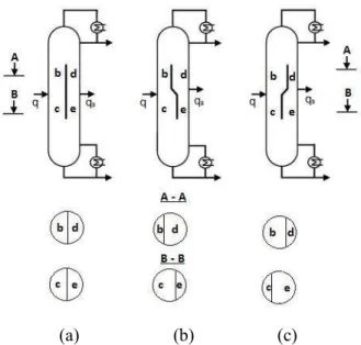
2.1.3 Divided wall column configurations
For ternary mixture separation, divided wall columns can be classified into one of three types, based on the position of the dividing wall: middle divided wall column (DWCM), lower divided wall column (DWCL), and upper divided wall column (DWCU) as shown in Fig. 2.7
(a) (b) (c)
FIGURE 2.7 Basic types of divided wall column: (a) Divided wall column middle, (b)
Divided wall column lower, (c) Divided wall column upper
Moreover, the dividing wall can use centered, off-centered or diagonal dividing walls, as shown in Figure 2.8 and Figure 2.9.
(a) (b) (c)
Chapter 2: Literature review
14
The dividing wall usually is placed in the middle as shown in the figure 2.8 (a), but off center positions of the dividing wall are also applied as the figure 2.8 (b) and (c) when the amount of the medium boiling component is small compared to the top and bottom products (Asprion, 2010).
For vapor feed and/or vapor side-draws a diagonal off center position of the dividing wall can be useful. In this case a more uniform distribution of the F factors, a measure of the maximum allowable vapor velocity for column, can be obtained in the partitioned sections of the column (Asprion, 2010).
(a) (b)
FIGURE 2.10 Divided wall column for separation of four-component mixture
(a) Kaibel column and (b) column with multiple partition walls
Dividing wall columns could be used for the separation of mixture that has more than three components. The number of configurations of the DWC systems has increased corresponding to an increased number of components. To separate a four component mixture, dividing wall columns could be applied as shown in Figure 2.10.
2.1.4 Divided wall column design parameters
The divided wall column has more design variables than a conventional distillation column. Figure 2.11 shows that there are ten design parameters, namely: reboiler duty (Qb), reflux ratio (R), number of theoretical stages (N1 ÷ N6), liquid split (RL), and vapor split (RV).
Chapter 2: Literature review
FIGURE 2.11 DWC design parameters
Design Parameters
N1 - N6 - Number of stages of each section RL – Liquid split RV – Vapor split R – Reflux ratio QB – Energy consumption Specification
F – Feed flow rate
zA, zB, zC – Feed composition D – Top product
S – Side product W – Bottom product
The liquid and vapor splits are defined as the ratio of the streams going to the prefractionator to the amount coming to the joint. At the top of the dividing wall, the flow of liquid is split (RL). At the bottom of the dividing wall, the flow of vapor is split (RV).
Thus, compared to a conventional distillation column, the design of divided wall columns is more difficult because of the larger amount of designed variables.
2.1.5 Control of divided wall columns
To separate a ternary mixture, the divided wall column offers significant savings in both energy and capital costs. More than 100 divided wall columns have been built globally by BASF. This section will give some relevant studies in which control and simulation aspects are presented.
In principle, Figure 2.11 shows the theoretically possible manipulated variables. They are the distillate stream (D), the reflux flow rate (R), the side stream (S), the bottom product stream (W), the feed stream (F), heat duty of the reboiler (QB), the liquid split (RL), and the vapor split (RV).
The simplest control structure is an extension of the control of a regular distillation column with a side stream (E. A. Wolff and Skogestad (1995)). Consider a ternary mixture A, B, and C carried out in the divided wall column. The distillate product purity (xD,A) is controlled by
manipulating the reflux flow rate(L2), the side stream purity (xS,B) is controlled by
Chapter 2: Literature review
16
controlled by manipulating the vapor boilup(v). In this case RL and RV are fixed and the outputs and inputs are:
y = ( xD,A xS,B xW,C ) u = ( L2 S v )
The mixture of ethanol/propanol/butanol is studied. By using linear tools, they concluded that the system is easy to control. However, if the desired purity of the product is higher, the system is difficult to control. To solve this problem, the reflux stream (L2), side stream (S), and boilup (v), the liquid split (RL) can be added to the set of manipulated variables to control the purity of the side stream but both linear and nonlinear tools predicted difficult control. M. Serra et al., (1999, 2000, and 2001) studied a hypothetical system with constant relative volatilities. Different controllability indices were used to select the pairing in a three-point control structure. The results show that the control structure of E. A.Wolff and Skogestad (1995) is the best structure.
Halvorsen and Skogestad (1997, 1999) proposed two important tasks that should be achieved by the prefractionator: Keep the heaviest component from going out to the top of the prefractionator and keep the lightest component going out to the bottom of the prefractionator. Therefore, in the control structure, the liquid split (RL) is used to control the level of the heavy impurity in the top of the prefractionator as shown in Figure 2.12.
FIGURE 2.12 Controller in the Petlyuk
column (E.A.Wolff and Skogestad (1995))
FIGURE 2.13 PI controller for a divided
wall column (Till Adrian et al., (2004)) Till Adrian et al. (2004) reported experimental results of a butanol (15 wt. %), pentanol (70 wt. %), hexanol (15 wt. %) system in which temperature control was used instead of
Chapter 2: Literature review
concentration control. The column used for the study was built at the Ludwigshafen site of BASF Aktiengesellschaft. The total height of the divided wall column was 11.5 m with a column diameter of 40 mm for the two parallel middle part of the column, and 55 mm for the upper part and lower part of the column. The positions of the controlled temperatures included the top of the prefractionator to control the heavy boiling component C from passing the top of the prefractionator, a stage above the side product to correct separation of component A and B and the lower part of the column to control the light boiling component A passing the lower part of the column as shown in Figure 2.13. A predictive control model was used to control the three temperatures. In this case, the maximum deviations of the controlled temperatures lie in the range of 2°C – 3°C. Moreover, the time to reach steady state is 2h at maximum for the pilot plant.
Wang and Wong (2007) also used temperature control instead of composition control in the divided wall column. A ternary mixture including ethanol – 1 propanol – 1 butanol is considered. The temperature in the bottom of the prefractionator was controlled by manipulating reboiler heat input. The temperature in the upper part of main column was controlled by manipulating reflux flowrate and the temperature near the base of the column was controlled by manipulating the side stream flowrate. In this article, liquid split is not used as a manipulate variable.
Ling and Luyben (2009) proposed a method to control the impurity of the three products and one composition in the prefractionator. The reflux flowrate, side stream flowrate, vapor boil up, and liquid split were chosen to be manipulated. Dynamic simulations demonstrated improved performance. Ling and Luyben (2010) also used temperature control. In the study, the separation of ternary mixture benzene – toluene – o xylene is considered.
Kiss A.A and R.C. van Diggelen (2010) applied more advanced controllers such as Linear Quadratic Gaussian control, Generic Model control and higher order controllers based on a H∞ loop shaping design procedure and the 𝜇 synthesis procedure. The controllers were
applied to a divided wall column in an industrial case study.
Buck et at. (2011) developed and test of a control system on a pilot plant. For the separation of the alcohols n-hexanol, n-octanol and n – decanol. It has a diameter of 68 mm and height of 11 m. In this study, the temperatures are also used as controlled variables instead of compositions to assure product purities because temperature measurement requires less effort and shorter time than online measurement of product purities. Three temperatures are controlled. One located at the top of the main column, one in the feed section, and one at the bottom of main column. The manipulated variables that are used to control these
Chapter 2: Literature review
18
temperatures are the distillate stream, the side stream, and the heat duty in the reboiler. In order to evaluate, compare and test the whole control system, the simulation and actual experiments are carried out in the pilot plant. The authors claimed that it is valuable to include the liquid split ratio above the dividing wall in the control system.
FIGURE 2.14 Control structures of divided wall column (Buck et at., (2011))
Deeptanshu Dwivedi et al. (2012) demonstrated experimentally that the vapor split can be used in practice for continuous operation as shown in Figure 2.15. The height of the column is 8 m and the inner diameter for the two parallel middle section is 50 mm while upper and lower parts are 70 mm diameter. To control the four-product Kaibel column, the four-point temperature control scheme is used. The temperature in the prefractionator can be controlled by using the vapor split while the liquid split is constant. In the main column, three temperatures are controlled by reflux ratio rate, upper side product stream, and lower side product stream. In this case, the liquid split is not used to control the system because it is available for optimizing an objective such as to reduce energy for a required purity specification. Experimental results show that the vapor split can be manipulated in feedback mode to achieve more energy efficient operation of the divided wall column.
FIGURE 2.15 Schematic and photograph of the two vapor split valves (Dwivedi D et al.,
Chapter 2: Literature review
2.1.6 Simulation of divided wall columns
Although the first application of a divided wall column was built in 1985 in Germany by BASF and have received more and more interest amongst academic and industrial researchers, it still cannot be established as a standard model in the commercial software packages such as Aspenplus, Chemcad or ProSimplus. Therefore, to arrange the divided wall column, there are four ways to simulate the system (Dejanovic et al., 2010). Firstly, for separation of a ternary mixture, divided wall columns can be represented as a single column in which various sections of divided wall column are situated in a vertical arrangement. Vapor and liquid flow within the model is regulated using liquid pumps around streams and vapor bypasses to imitate divided wall column. It is called the pump-around model as shown in Figure 2.16.
FIGURE 2.16 Pump around model of divided wall column
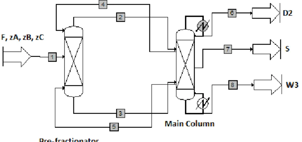
Secondly, in Figure 2.17, divided wall columns can be represented with a two-column sequence, known as the prefractionator (or side column) and the main column, which are thermodynamically equivalent to a divided wall column.
Chapter 2: Literature review
20
This method is easier to set-up and offers a bit more flexibility than the pump around model. Therefore it is usually the preferred choice for design and optimization.
FIGURE 2.18 Four columns sequence model
Thirdly, divided wall columns can be modelled with a four column sequence as shown in Figure 2.18. It reflects the actual situation best and is considered as the most suitable configuration for dynamic simulation. However, it is the most difficult to initialize because it requires initialization of the interconnecting streams.
2.1.7 Divided wall column applications
In 1985, the first application of a DWC was installed by BASF in Ludwigshafen, Germany. In 2010, there are now more than 125 divided wall columns in operation globally, of which 116 are divided wall columns for separation of three-component mixtures, 2 are divided wall columns for separation of mixtures with more than three components. Most of them are installed by BASF (around 70 packed DWC). The number of divided wall columns is expected to reach about 350 DWC in 2015 if the rate of growth remains constant (Yildirim et al., 2011). Structured or random packing or trays are used in the divided wall column. Operating pressures in the system range between 2 mbar and 10 bars. The diameters of dividing wall column are between 0.6 m and 4 m at BASF. The largest column that is constructed by Linde AG for Sasol in Johannesburg, South Africa has a height of 107 m and diameter of more than 5 m (Yildirim et al., 2011; Parkinson, 2005). One typical application for the divided wall column is the reduction of the benzene content in motor gasoline to less
Chapter 2: Literature review
than 1 per cent on a volume basis. The divided wall column can also be applied to the separation of C4 isomers with a feed of mixed C5s and C4s. It can save energy usage by 26.5% compared to conventional systems.
Slade. B et al., (2005) reported the successful revamp of a conventional tray distillation column for xylene separation (3.8/4.3 m diameter). The column takes a xylene side stream from reformate to feed an aromatics plant to make higher value products. The existing distillation column was a traditional column with 51 trays. The feed location was tray 38 and side product was taken at tray 20. The revamp column configuration was a divided wall column with 51 trays. The dividing wall ran from tray 14 up to tray 39. The feed was at tray 27 in the feed section and the xylene product was taken at tray 28 in the side section. Test runs were carried out on the divided wall column during June and July 2005.
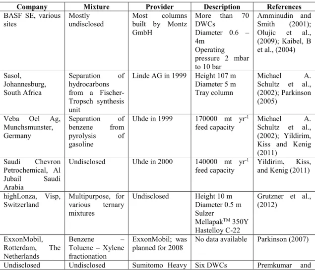
Table 2.1 shows the industrially available divided wall column applications for ternary mixtures (Yildirim et al., 2011).
TABLE 2.1 Industrial applications of DWCs for ternary systems (Yildirim et al., 2011)
Company Mixture Provider Description References
BASF SE, various
sites Mostly undisclosed Most built by Montz columns GmbH More than 70 DWCs Diameter 0.6 – 4m Operating pressure 2 mbar to 10 bar Amminudin and Smith (2001); Olujic et al., (2009); Kaibel, B et al., (2004) Sasol, Johannesburg, South Africa Separation of hydrocarbons from a Fischer-Tropsch synthesis unit Linde AG in 1999 Height 107 m Diameter 5 m Tray column Michael A. Schultz et al., (2002); Parkinson (2005)
Veba Oel Ag, Munchsmunster, Germany Separation of benzene from pyrolysis of gasoline Uhde in 1999 170000 mt yr-1
feed capacity Michael Schultz et al., A. (2002); Yildirim, Kiss and Kenig (2011) Saudi Chevron Petrochemical, Al Jubail Saudi Arabia Undisclosed Uhde in 2000 140000 mt yr-1
feed capacity Yildirim, Kiss, and Kenig (2011) highLonza, Visp,
Switzerland Multipurpose, for various ternary mixtures Undisclosed Height 10 m Diameter 0.5 m Sulzer MellapakTM 350Y Hastelloy C-22 Grutzner et al., (2012) ExxonMobil, Rotterdam, The Netherlands Benzene – Toluene – Xylene fractionation ExxonMobil; was
planned for 2008 No data available Parkinson (2007)
Chapter 2: Literature review
22
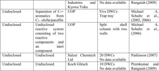
Industries and
Kyowa Yuka No data available Rangaiah (2009) Undisclosed Separation of C7+
aromatics from C7+ olefin/paraffin
UOP Five DWCs
Trap tray Michael Schultz et al., A. (2002, 2006) Undisclosed Undisclosed reactive system consisting of two reactive components and an inert component
UOP Split shell
column with two walls
Michael A.
Schultz et al., (2006)
Undisclosed Undisclosed Sulzer Chemtech
Ltd 20 DWCs No data available Parkinson (2007)
Undisclosed Undisclosed Koch Glitsch 10 DWCs
No data available Premkumar and Rangaiah (2009) For the separation of mixtures with more than three components, Table 2.2 shows two applications of divided wall columns.
TABLE 2.2 Industrial applications of divided wall columns for multicomponent mixtures
Company System Constructor Features Reference
BASF SE Recovery of four
component mixture of fine chemical
intermediates
BASF SE/Montz
GmbH since 2002 Single wall Height 34 m Diameter 3.6 m Column works under high vacuum Dejanovic et al (2011a), Olujic et al. (2009) Undisclosed customer in the Far East Integration of a product separator and an HPNA stripper
Designed by UOP Five product
streams Schultz et al. (2006), Parkinson (2007)
2.2 CONCEPTUAL DESIGN OF DIVIDED WALL COLUMN: REVIEW
The divided wall column system has many known advantages, but the lack of knowledge for design, operating, and control may cause limited growth of divided wall column in the process industry. Almost all papers that have been published were restricted to ternary mixtures with three products, sharp separations, saturated liquid feed, constant flowrate and constant relative volatility. In the section, a review of the methods for design of divided wall columns and reactive divided wall column will be presented.
The design of divided wall columns or fully thermally coupled distillations is more complex than traditional distillation because it has more degrees of freedom. A number of papers have
Chapter 2: Literature review
been published on the subject which focus on the calculation of the minimum vapor requirement and determined the number of stages in the various column sections.
C. Triantafyllou and Smith (1992) published a design oriented shortcut method for three products in a divided wall column based on the Fenske-Underwood-Gilliland-Kirkbridge model (FUGK). In this paper, they presented a method to decompose a divided wall column into a three-traditional-column model. By using the decomposition method, they assume that heat transfer across the column wall can be neglected, hence making the divided wall column equivalent to a fully thermally coupled distillation. The prefractionator is considered like a traditional column if a partial condenser and a partial reboiler are used. The main column can be represented as two traditional columns if we assume a total reboiler for the upper part of the main column and a total condenser for the lower part of the main column. The interconnecting streams are considered as the feed flowrates with superheated vapor and sub-cooled liquid conditions, respectively. The FUGK method can be applied to determine operational and structural parameters for each column. The minimum number of equilibrium stages can determined by the Fenske equation, the minimum reflux ratio can be determined by using the Underwood equation, the number of stages can be determined by the Gilliland method when choosing operating reflux ratio, and feed location can be determined by the Kirkbride method. The reflux ratio of the prefractionator is adjusted until its number of stages equals the number of the side section. The recoveries in the prefractionator column are optimized for the minimum vapor flowrate or the minimum number of stages.
Amminidin et al., (2001) proposed a semi-rigorous design method based on equilibrium stage composition concept. Certain assumptions are as follows: constant molar overflow, constant relative volatility, and estimation of component distribution at minimum reflux. Their design procedure starts from defining the products composition, and works backward to determine the design parameters required to achieve them. Therefore, firstly, by using the method of Van Dongen and Doherty (1985), a feasible product distribution is estimated for the composition of the top, middle and bottom products, the minimum reflux ratio and the minimum boil-up ratio. Any distillation operation lies between the two limits of total reflux and minimum reflux ratios. At total reflux ratio, the number of stages is minimized and energy consumption is maximized. At the minimum reflux ratio, the number of stages is maximized and energy consumption is minimized. Therefore, a product distribution must be chosen between the two conditions. Secondly, using the equilibrium stage concept the number of stages, flow rates, feed stage and side stream location for the fully thermally coupled distillation are estimated.
Chapter 2: Literature review
24
An approximate design procedure for fully thermally coupled distillation column is proposed by Kim, Y.H (2002). The Fenske equation is applied to the main column to determine minimum number of stages. However, the author believed that the design of the prefractionator cannot follow the Fenske equation because the end compositions are unknown. Therefore, a stage-to-stage computation is proposed. Then, the number of stages in the system is taken as twice the minimum number of stages. The minimum vapor flowrate was determined by the Underwood equation. The liquid flowrate of the main column is determined by checking the compositions of the products. Clearly, they take twice the minimum number of stages as the number of theoretical trays is considered to be equal to two times the minimum number of stages. It is not always true.
Halvorsen, I.J and Sigurd Skogestad (2003) proposed the Vmin diagram method to determine the minimum energy consumption. To use the method, they assume constant molar flowrates, constant relative volatilities, and an infinite number of stages. Firstly, the Vmin diagram is drawn based on the Underwood equation. The minimum energy requirement for separation of a feed mixture of n components into n pure products is given by:
VminPetlyuk = max ∑ αiziF αi− θj
; j ∈ {1, n − 1}
j
i=1
Here: θj are the n-1 common Underwood roots found from:
1 − q = ∑ αizi αi− θ n
i=1
Underwood roots obey α1 > θ1> α2> θ2> ⋯ > θn−1> αn
Where: q is liquid fraction in the feed (F) z is the feed composition
Secondly, they choose the actual flowrate around 10% and the minimum number of stages was calculated based on the Underwood equation.
Calzon-McConville, C. J et al., (2006) presented an energy efficient design procedure for optimization of the thermally coupled distillation sequences with initial designs based on the design of conventional distillation sequences. In the first step, it is assumed that each column performs with specified recoveries of components of 98 % (light and heavy key components) and by using the shortcut method (FUG model), the number of stages of conventional distillation schemes are obtained. In the second step, the stage arrangements in the integrated configurations are obtained; finally, an optimization procedure is used to minimize energy consumption. The energy-efficient design procedure for thermally coupled distillation
Chapter 2: Literature review
sequences is applied not only for the separation of ternary and quaternary mixtures but also to the separation of five or more component mixtures.
Sotudeh, N and Bahram Hashemi Shahraki (2007, 2008) proposed a shortcut method for the design of a divided wall column based only on the Underwood equation because authors believe that using the Fenske equation for calculating the minimum number of stages is not adequate for designing divided wall columns. The theoretical number of stages can be calculated by using the basic Underwood equation. In this method, the number of stages in the prefractionator is set to be the same as in the side section. Clearly, we cannot know that the number of stages of prefractionator is correct or not. Moreover, the paper does not carry out simulations to confirm the method.
Ramirez-Corona, N et al., (2010) presented an optimization procedure for the Petlyuk distillation system. The procedure used the FUG model to determine the structural design of the divided wall column as well as the mass and energy balances, the thermodynamic relationships, and cost equations. The objective function was set as the minimization of the total annual cost. In the procedure, they estimated the composition of the interconnection streams between the prefractionator and the main column by solving the feed line and the operating line equations.
yi= ( q q − 1) xi− xi,D q − 1 yi= ( R R + 1) xi+ xi,D R + 1 Combining these equations, one obtains:
xi= zi. (R + 1) + xi,D. (q − 1) R + q yi = R. zi+ q. xi,D R + q
Chu, K. T et al., (2011) presented a new shortcut method based on the efficient net flow model to determine the composition of the key components. They then applied the shortcut method of Fenske, Underwood, Gilliland and Kirkbride to determine the number of stages of each section. Liquid split RL and vapor split RV are dependent variables due to the constant
molar flow assumption. The values of RL and RV are chosen to obtain the same number trays
in the prefractionator and side section.
Table 2.3 shows the summary of several shortcut methods for design of divided wall columns.
Chapter 2: Literature review
26
TABLE 2.3 Summary of several shortcut methods for design divided wall column
References Model Method Hypothesis Mixture analysis
Triantafyllou and
Smith (1992) Three – column sequence model FUGK method Minimum cost of system Constant relative volatilities Constant molar flows i-butane/1-butene/n-butane/trans-2-butene/cis-2-butene Amminidin et al.
(2001) Three sequence model column Semi-rigorous design method based on the equilibrium stage composition concept
Constant molar overflow. Constant relative volatilities. Estimate product distribution at minimum reflux.
Ethylene/Propene/n-Propane/i- butane/1-butane/n-butane/i-Pentane/n-Pentane/n-Hexane Young Han Kim et
al. (2002) Two sequence model (pre-– column fractionator and main column)
Fenske equation for the main column and a stage-to-stage computation for the pre-fractionator.
Take twice the minimum number of stages as the theoretical trays
Ideal equilibrium is assumed between the vapor and liquid of interlinking streams and the shortcut design equations of multi component distillation columns.
Methanol/Ethanol/water Cyclohexane/n-heptane/toluene s-butanol/i-butanol/n-butanol
Ivar J. Halvorsen and Sigurd Skogestad (2003, 2011)
Two – column
sequence model (pre-fractionator and main column)
Vmin diagram method.
Underwood’s equation. Constant molar flow Infinite number of stages Constant relative volatilities Noori Sotudeh and
Bahram Hashemi
Shahraki (2007, 2008)
Three – column
sequence model Underwood’s equation.Number of stages in the pre-fractionator is set to be the same as in the side section.
The compositions of interconnection streams are design variables.
Constant relative volatilities Benzene/Toluene/Xylene
i-butane/1-butene/n-butane/trans-2-butene/cis-2-butene
Nelly Ramirez
Corona et al. (2010) Three – column sequence model FUGK method They calculate the composition of
interconnection streams.
Minimization of the total annual cost.
Constant relative volatilities Constant molar flowrate The interconnecting streams are saturated.
n-pentane/n-hexane/n-heptane n-butane/i-pentane/n-pentane i-pentane/n-pentane/n-hexane Kai Ti Chu et al.
(2011) Six different sections model. Applied the components net flow model. FUGK method
Constant relative volatilities Constant molar flowrate The column is symmetric
Ethanol/n-Propanol/n-Butanol Benzene/Toluene/EthylBenzene Christopher Jorge
Calzon-McConville et al. (2006)
Superstructure model Based on the design of conventional distillation sequences, the stages are rearranged to the integrated configurations.
Minimize energy consumption
n-butane/ isopentane/
Chapter 2: Literature review
Based on the above analysis, we can conclude that a lot of papers focused on the design, simulation and control for divided wall column. However, these methods still have drawbacks. The method of C. Triantafyllou et al., (1992) applied the FUGK model that can quickly and easily determine operational and structural parameters of divided wall columns. However the application of the Fenske equation for the estimation of the minimum number of stages of a divided wall column is not correct since the composition of the liquid stream returning from the main column is not equal to the composition of the vapor entering the main column at the connection points. Kim (2002) applied a stage-to-stage computation method instead of the Fenske equation for the prefractionator. However the actual number of stages in the system takes twice the minimum number of stages. Sotudeh (2007) used only the Underwood equation to determine the number of stages in the main column and they set the number of stages of the prefractionator to be the same number of stages as in the side section. Ramirez-Corona et al., (2010) also applied the FUGK method and estimated the composition of interconnecting streams.
Moreover, all the previous methods have not considered the position and configuration of dividing wall in the column and a great part of them are restricted to ternary mixtures with a feed quality (q) equal to 1.
2.3 CONCEPTUAL DESIGN OF REACTIVE DIVIDED WALL COLUMN: REVIEW
A reactive divided wall column represents a combination of a reactor and a separation unit in one divided wall column or a combination of reactive distillation and divided wall column technology. Kaibel and Miller (2005) proposed the reactive dividing wall column as one of the new possible application areas for dividing wall columns. The design of reactive dividing wall columns is considered as a combination of a design of a reactive distillation column and a design of a non-reactive dividing wall column. The design, simulation, and control of non-reactive divided wall columns is still a new research area.
Mueller, I et al. (2007) decomposed the reactive divided wall column step-by-step into single non-reactive and non-reactive columns as shown in Figure 2.19. Step 1: if the heat transfer across the dividing wall is neglected, the divided wall column is thermodynamically equivalent to the Petlyuk column. Step 2: If one partial re-boiler and one partial condenser is added into the prefractionator, the four liquid and vapor streams between the columns can be replaced by two streams. Step 3: The three traditional distillation columns are equivalent to the prefractionator configuration if one total
Chapter 2: Literature review
28
reboiler is added to column 2 and one total condenser to column 3. In this configuration, the reaction and separation processes occur in column 1 (reactive column). In Column 2 and column 3 (non-reactive columns) only separation occurs.
FIGURE 2.19 Decomposition into simple column sequences (grey area: reactive zone) (Mueller, I
et al. (2007))
For the non-reactive columns, the shortcut methods suggested by Underwood, Fenske, and Gilliland are applied. The Fenske’s equation gives the minimum number of equilibrium stages at total reflux. The minimum reflux ratio is calculated by Underwood’s equation. The Gilliland correlation provides the actual number of theoretical stages. Then, the feed position is determined by the Kirkbride equation. For the reactive columns, they applied the rate-based approach. The actual rates of multicomponent mass and heat transport between liquid and vapor phases can be directly accounted for. In the paper, they suggested that the reactive divided wall column should be used for (1) Reactive systems with more than two products which should each be obtained as a pure fraction; (2) Reactive systems with an inert component and with a desired separation of both products and inert component. (3) Reactive systems with an excess of a reagent, which should be separated before being recycled. Mueller et al. (2007) also presented another method to design the reactive dividing wall column in which the rate-based stage model is applied for both non-reactive and reactive sections.
Guido Daniel et al. (2006) proposed a procedure to obtain feasible designs for a reactive dividing wall column. In the paper, the reactive divided wall column is represented by using a prefractionator and a main column. It is assumed that reaction only occurs in the prefractionator and the main column is used to separate the reaction products. The methodology is based on the