HAL Id: hal-01911995
https://hal.archives-ouvertes.fr/hal-01911995
Submitted on 5 Nov 2018
HAL is a multi-disciplinary open access
archive for the deposit and dissemination of
sci-entific research documents, whether they are
pub-lished or not. The documents may come from
teaching and research institutions in France or
abroad, or from public or private research centers.
L’archive ouverte pluridisciplinaire HAL, est
destinée au dépôt et à la diffusion de documents
scientifiques de niveau recherche, publiés ou non,
émanant des établissements d’enseignement et de
recherche français ou étrangers, des laboratoires
publics ou privés.
Design and simulation of divided wall column:
Experimental validation and sensitivity analysis
Trung Dung Nguyen, David Rouzineau, Michel Meyer, Xuan Mi Meyer
To cite this version:
Trung Dung Nguyen, David Rouzineau, Michel Meyer, Xuan Mi Meyer. Design and simulation of
divided wall column: Experimental validation and sensitivity analysis. Chemical Engineering and
Processing: Process Intensification, Elsevier, 2016, 104, pp.94-111. �10.1016/j.cep.2016.02.012�.
�hal-01911995�
O
pen
A
rchive
T
oulouse
A
rchive
O
uverte
(OATAO)
OATAO is an open access repository that collects the work of some Toulouse
researchers and makes it freely available over the web where possible.
This is an author’s version published in:
http://oatao.univ-toulouse.fr/
20535
To cite this version:
Nguyen, Trung Dung and Rouzineau, David and Meyer, Michel and Meyer, Xuân-Mi
Design and simulation of divided wall column: Experimental validation and sensitivity
analysis. (2016) Chemical Engineering and Processing: Process Intensification, 104.
94-111. ISSN 0255-2701
Any correspondance concerning this service should be sent to the repository administrator:
[email protected]
Design
and
simulation
of
divided
wall
column:
Experimental
validation
and
sensitivity
analysis
Trung
Dung
Nguyen
a,b,
David
Rouzineau
a,*
,
Michel
Meyer
a,
Xuan
Meyer
aaUNIVERSITEDETOULOUSE,ENSIACET—INPdeToulouse,LaboratoiredeGénieChimique,UMRCNRS5503,4alléeEmileMonso,BP44362,31432Toulouse
Cedex4,France
bHanoiUniversityofScienceandTechnology,1DaiCoVietStreet,Hanoi,Vietnam
Keywords:
Processintensification Dividedwallcolumn Processdesign Simulation Pilotplant Sensitivityanalysis
ABSTRACT
Thisarticledealswithdesignandsimulationofdividedwallcolumn.Designparametersareprovidedto therigoroussimulationintheProSimPlus1software.Theresultsshowthattheprocedurecandetermine
parametersquicklyinthecasestudiesandcangiveagoodinitializationforrigoroussimulation.Secondly, apilotplanthasbeendesign,builtandoperatedinourlaboratory.Thepilotplantwillprovidenecessary experimentalevidencetovalidatethepreviousprocedure.Ternarymixtureandfour-componentmixture ofalcoholshavebeenusedinourpilotplantinsteadystateconditions.Theresultsshowthatthe compositionof products,composition andtemperature profilealong thecolumnare inverygood agreementwithsimulationresults.Finally,inordertodeterminetheoptimalparametersofdividedwall columns,theeffectsofthestructuralparametersofthedividedwallcolumnsuchastheheightofthe wall,theverticalpositionofthewallandnumberofstagesofeachsectionareanalyzed.Ternarydiagram isusedasanindicatorbothinshowingwhatthemosteconomicalconfigurationisandinshowingthe distillationboundary.
1.Introduction
Thedividedwallcolumn(DWC)hasmanyknownadvantages, andmanydesignmethodologiesforDWC’shavebeenpublished over thelastyears. Almostallpapers that havebeenpublished were restricted toternarymixtures with three products, sharp separations,saturatedliquidfeed,constantflowrateandconstant relative volatility. The design of divided wall columns or fully thermallycoupleddistillationsismorecomplexthantraditional distillationbecauseithasmoredegreesoffreedom.Anumberof papers have beenpublishedonthesubject which focusonthe calculationoftheminimumvaporrequirementanddetermined thenumberofstagesinthevariouscolumnsections.Triantafyllou and Smith[4] publishedadesign orientedshortcutmethodfor three productsin a dividedwall column basedontheFenske– Underwood–Gilliland–Kirkbridge model (FUGK). In this paper, theypresentedamethodtodecomposeadividedwallcolumninto a three-traditional-column model. By using the decomposition method,theyassumethatheattransferacrossthecolumnwallcan beneglected,hencemakingthedividedwallcolumnequivalentto a fully thermally coupled distillation. The prefractionator is
consideredlikeatraditionalcolumnifapartialcondenseranda partialreboilerareused.Themaincolumncanberepresentedas twotraditionalcolumnsifweassumeatotalreboilerfortheupper partofthemaincolumnandatotalcondenserforthelowerpartof themaincolumn.Theinterconnectingstreamsareconsideredas thefeedflowrateswithsuperheatedvaporandsub-cooledliquid conditions, respectively. The FUGK method can be applied to determineoperationalandstructuralparametersforeachcolumn. Theminimumnumberofequilibriumstagescanbedeterminedby theFenskeequation,theminimumrefluxratiocanbedetermined byusingtheUnderwoodequation,thenumberofstagescanbe determined by the Gilliland method when choosing operating refluxratio,andfeedlocationcanbedeterminedbytheKirkbride method.Therefluxratiooftheprefractionatorisadjusteduntilits number of stages equals the number of the side section. The recoveries in the prefractionatorcolumn are optimized for the minimumvaporflowrateortheminimumnumberofstages.
Amminudinetal.[1,2]proposedasemi-rigorousdesignmethod basedonequilibriumstagecompositionconcept.Certain assump-tions areas follows:constant molaroverflow,constant relative volatility,andestimationofcomponentdistributionatminimum reflux.Theirdesignprocedurestartsfromdefiningtheproducts composition, and works backward to determine the design parametersrequiredtoachievethem.Therefore,firstly,byusing
* Correspondingauthor.
themethodofVanDongenandDoherty[18],afeasibleproduct distributionisestimatedforthecompositionofthetop,middleand bottomproducts,theminimumrefluxratioandtheminimum boil-upratio.Anydistillationoperationliesbetweenthetwolimitsof totalrefluxandminimumreflux ratios.Attotalrefluxratio,the number of stages is minimized and energy consumption is maximized.Attheminimumrefluxratio,thenumberof stages ismaximizedandenergyconsumptionisminimized.Therefore,a productdistributionmustbechosenbetweenthetwoconditions. Secondly, using the equilibrium stage concept the number of stages,flowrates,feedstageandsidestreamlocationforthefully thermallycoupleddistillationareestimated.
Anapproximatedesignprocedureforfullythermallycoupled distillationcolumnisproposedbyKim[11].TheFenskeequationis appliedtothemain columntodetermineminimum numberof stages. However, the author believed that the design of the prefractionatorcannotfollowtheFenskeequationbecausetheend compositionsareunknown.Therefore,astage-to-stage computa-tionisproposed.Then,thenumberofstagesinthesystemistaken as twicetheminimum number of stages. The minimum vapor flowratewasdeterminedbytheUnderwoodequation.Theliquid flowrate of the main column is determined by checking the compositions of the products. Clearly, they take twice the
minimum number ofstages as thenumber of theoreticaltrays isconsideredtobeequaltotwotimestheminimumnumberof stages.Itisnotalwaystrue.
Halvorsen and Skogestad [7,10] proposed the Vmin diagram methodtodeterminetheminimumenergyconsumption.Touse the method, they assume constant molar flowrates, constant relativevolatilities,andaninfinitenumberofstages.Firstly,the Vmindiagram is drawnbased onthe Underwoodequation. The minimumenergyrequirementforseparationofafeedmixtureofn componentsintonpureproductsisgivenby:
VPetlyukmin ¼maxX
j i¼1
a
iziFa
i"u
j;j2f1;n"1gHere:
u
jarethen"1commonUnderwoodrootsfoundfrom:1"q¼X
n i¼1
a
izia
i"u
Underwoodrootsobey
a
1>u
1>a
2>u
2>...>u
n"1>a
nwhere:q is liquid fractionin thefeed (F) and zis the feed composition
Secondly,theychoosetheactualflowratearound10%andthe minimum number of stages was calculated based on the Underwoodequation.
Calzon-McConville et al. [5] presented an energy efficient design procedure for optimization of the thermally coupled distillationsequenceswithinitialdesignsbasedonthedesignof conventionaldistillationsequences.Inthefirststep,itisassumed thateach columnperformswithspecifiedrecoveriesof compo-nentsof98%(lightandheavykeycomponents)andbyusingthe shortcutmethod(FUGmodel),thenumberofstagesof conven-tionaldistillationschemesareobtained. Inthesecondstep,the stagearrangementsintheintegratedconfigurationsareobtained; finally, an optimization procedure is used to minimize energy consumption.Theenergy-efficientdesignprocedureforthermally coupled distillation sequences is applied not only for the separation of ternaryand quaternary mixtures butalso for the separationoffiveormorecomponentmixtures.
SotudehandShahraki[14,15]proposedashortcutmethodfor thedesignofadividedwallcolumnbasedonlyontheUnderwood equationbecauseauthorsbelievethatusingtheFenskeequation forcalculatingtheminimumnumberofstagesisnotadequatefor designingdividedwallcolumns.Thetheoreticalnumberofstages canbecalculatedbyusingthebasicUnderwoodequation.Inthis method,thenumberofstagesintheprefractionatorissettobethe same as in the side section. Clearly, we cannot know that the numberofstagesofprefractionatoriscorrectornot.Moreover,the paperdoesnotcarryoutsimulationstoconfirmthemethod.
Ramirez-Coronaetal.[13]presentedanoptimizationprocedure forthePetlyukdistillationsystem.TheprocedureusedtheFUG model to determine the structural design of the divided wall columnaswellasthemassandenergybalances,the thermody-namic relationships, and cost equations.The objectivefunction was set as the minimization of the total annual cost. In the procedure,theyestimatedthecompositionoftheinterconnection streams between the prefractionator and the main column by solvingthefeedlineandtheoperatinglineequations.
yi¼ q q"1 " # xi" xi;D q"1 yi¼ R Rþ1 " # xiþ xi;D Rþ1 Nomenclature
A,B,C Ternarymixture(Aisthemostvolatilecomponent andCistheleastvolatilecomponent)
D Topproductflowrate(kmolh"1) F Feedflowrate(kmolh"1)
L Liquidflowrateintherectifyingsection(kmolh"1) L Liquidflowrateinthestrippingsection(kmolh"1) N Numberofstages
q Qualityofthestream R Refluxratio
RL Liquid split between prefractionator and main
column
RV Vapor split between prefractionator and main
column
S Sideproductflowrate(kmolh"1)
V Vaporflowrateintherectifyingsection(kmolh"1) V Vaporflowrateinthestrippingsection(kmolh"1) x Molefractionattheproductstream
W Bottomproductflowrate(kmolh"1) z Molefractionatthefeedstream Subscripts
1 ColumnI 2 ColumnII 3 ColumnIII
b,c,d,e sectionsseparatedbydividingwall HK Heaviestkeycomponent
LK Lightestkeycomponent min minimumvalue R Rectifyingsection S Strippingsection Greeksymbols
a
Relativevolatilityofcomponentt
Recoveryratioofthecomponentu
;u
0;u
00 RootsofUnderwood’sequationv
G Gasvelocity(ms"1)Combiningtheseequations,oneobtains: xi¼ ziðRþ1Þþxi;Dðq"1Þ Rþq yi¼Rziþqxi;D Rþq
Chu et al. [6] presented a new shortcut methodbased onthe efficientnetflowmodeltodeterminethecompositionofthekey components.Theythen appliedtheshortcut methodof Fenske, Underwood,GillilandandKirkbridetodeterminethenumberof stages of each section. Liquid split RL and vapor split RV are dependentvariablesduetotheconstantmolarflowassumption. ThevaluesofRLandRVarechosentoobtainthesamenumberof traysintheprefractionatorandinthesidesection.Table1shows thesummary ofseveral shortcutmethodsfordesign ofdivided wallcolumns.Basedontheaboveanalysis,wecanconcludethata lotofpapersfocusedonthedesignandsimulationfordividedwall column. However, these methods still have drawbacks. The methodof TriantafyllouandSmith[4] appliedtheFUGKmodel thatcanquicklyandeasilydetermineoperationalandstructural parametersofdividedwallcolumns.Howevertheapplicationof theFenskeequationfortheestimationoftheminimumnumberof stagesofadividedwallcolumnisnotcorrectsincethecomposition oftheliquidstreamreturningfromthemaincolumnisnotequalto the compositionof thevapor entering themain column atthe connectionpoints.Kim[11]appliedastage-to-stagecomputation method instead of theFenske equation for theprefractionator.
Howevertheactualnumberofstagesinthesystemtakestwicethe minimumnumberofstages.SotudehandShahraki[14]usedonly theUnderwoodequationtodeterminethenumberofstagesinthe main column and they set the number of stages of the prefractionatortobethesamenumber ofstages asin theside section.Ramirez-Coronaetal.[13]alsoappliedtheFUGKmethod and estimated the composition of interconnecting streams. Moreover, all the previous methods are restricted to ternary mixtureswithafeedquality(q)equalto1.
2.Designandsimulationprocedurefordividedwallcolumn 2.1.Modeldesign
This paragraph aims to present, by application of standard shortcutmethod(FUGKmodel)andusingthecomponentnetflow model, a procedure for designing divided wall columns. The approachallowsrapiddeterminationoftheminimumvaporflow rate,minimumrefluxratio,andnumberofstagesforeachsection
Table1
Summaryofseveralshortcutmethodsfordesignofdividedwallcolumns.
References Model Method Hypothesis Mixtureanalysis Triantafyllou andSmith [4] Three—column sequencemodel FUGKmethod Minimumcostofsystem
Constantrelativevolatilities Constantmolarflows
i-Butane/1-butene/n-butane/ trans-2-butene/cis-2-butene Amminudin etal.[2] Three—column sequencemodel
Semi-rigorousdesignmethodbasedon theequilibriumstagecomposition concept
Constantmolaroverflow Constantrelativevolatilities
Estimateproductdistributionatminimumreflux
Ethylene/propene/n-propane/i-butane/1-butane/ n-butane/i-pentane/n-pentane/n-hexane Kim[11] Two—column
sequencemodel (pre-fractionatorandmain column)
Fenskeequationforthemaincolumn andastage-to-stagecomputationfor thepre-fractionator.
Taketwicetheminimumnumberof stagesasthenumberoftheoretical stages
Idealequilibriumisassumedbetweenthevaporand liquidofinterlinkingstreamsandtheshortcutdesign equationsofmulticomponentdistillationcolumns.
Methanol/ethanol/water Cyclohexane/n-heptane/ toluene s-Butanol/i-butanol/n-butanol Halvorsen and Skogestad [7,10] Two—column sequencemodel (pre-fractionatorandmain column)
Vmindiagrammethod
Underwood’sequation
Constantmolarflow Infinitenumberofstages Constantrelativevolatilities Sotudehand Shahraki [15] Three—column sequencemodel Underwood’sequation Numberofstagesinthe pre-fractionatorissettobethesameasin thesidesection
Thecompositionsofinterconnection streamsaredesignvariables
Constantrelativevolatilities Benzene/toluene/Xylene i-Butane/1-butene/n-butane/ trans-2-butene/cis-2-butene Ramirez-Corona etal.[13] Three—column sequencemodel FUGKmethod
Theycalculatethecompositionof interconnectionstreamsMinimization ofthetotalannualcost
Constantrelativevolatilities Constantmolarflowrate
Theinterconnectingstreamsaresaturated
n-Pentane/n-hexane/n-heptane n-Butane/i-pentane/n-pentane i-Pentane/n-pentane/n-hexane
Chuetal.[6] Sixdifferentsections model
Appliedthecomponentsnetflowmodel FUGKmethod
Constantrelativevolatilities Constantmolarflowrate Thecolumnissymmetric
Ethanol/n-propanol/n-butanol Benzene/toluene/ ethylbenzene Calzon-McConville etal.[5]
Superstructuremodel Basedonthedesignofconventional distillationsequences,thestagesare rearrangedtotheintegrated configurations
Minimizeenergyconsumption
n-Butane/isopentane/ n-Pentane/n-hexane/n-heptane
Table2
UnknownvariablesandspecificationsofDWCsystem.
Unknownvariables Specifications Distillateproduct D2;xA;D2;xB;D2;xC;D2 xA;D2 andxC;D2
Sideproduct S;xA;S;xB;S;xC;S xB;S andxA;SorxC;S orxA;S
xC;S
bychoosinganoperatingrefluxratio,liquidandvaporsplitvalues, andthepossiblepositionandconfigurationofthedividingwall. Moreover,thecompositionsofinterconnectingstreamsbetween theprefractionatorandthemaincolumnarealsoestimatedandset astheinitialconditionsforsimulationinProSimPlus1software.
Assumptionsandmodeldesign
Tousethestandardshortcutmethod,thecomponentnetflow model,andsimplifiedmodelofadividedwallcolumn,weassume that:
(1)Therelativevolatilityofcomponentsisconstant;
(2)Thevaporandliquidflowsineachsectionofthedividedwall columnareconstant;
(3)Thepressureofthesystemisconstant;
(4)Theheattransferacrossthedividingwallisneglected; (5)Theheatlossesfromthecolumnwallsarenegligible; (6)Vapor–liquidequilibriumisachievedoneachstage;
(7)Theheavynon-keycomponentisassumedtogocompletelyto the bottom of column II (Fig. 2) and the light non-key componentisassumedtogocompletelytothetopofcolumnIII (Fig.2);
Kister[9]definedthatkeycomponentsarethetwocomponents inthefeedmixturewhoseseparationisspecified.Theyarecalled lightkey component(morevolatile) andheavy keycomponent (lessvolatile).Othercomponentsarecallednon-keycomponents. Anycomponentslighterthanthelightkeyarecalledlightnon-key components,whilethoseheavier thantheheavykeyarecalled heavynon-keyscomponents.Thecomponentsthatliebetweenthe light key and the heavy key are called distributed non-key components.Theprocedure canbeappliednotonlyforternary mixturesbutalsoforfourcomponentmixtures.Tosimplify,we considerseparationofaternarymixtureA,B,andC,inwhichAis thelightestcomponentandCistheheaviestcomponent.Thefeed flowrate is F (kmol/h), feed composition zA,zB, and zC, and recoveriesorpurities ofcomponentin dividedwall columnare known.Therelativevolatilitiesofeach componentareconstant (assumption1).
Thefeedcompositionislistedindecreasingorderoftherelative volatilityofthecomponent:
a
A>a
B>a
C¼1The minimum number of stages at total reflux may be estimated byusing the Fenske equation. It is appliedwith the assumptionthatallstagesreachequilibrium(assumption6)and requiresa constant relativevolatility
a
throughoutthecolumn(assumption 1). To determine the minimum reflux ratio, the equationsdevelopedbyUnderwoodarebasedontheassumption (2):constantmolarflowrate.Then, theknowledgeofminimum stagesandminimumrefluxratioinacolumncanberelatedtothe actual number of stages and the actualreflux required by the Gillilandcorrelation.Finally,thefeedstagecanbeestimatedby usingtheKirkbrideequation.
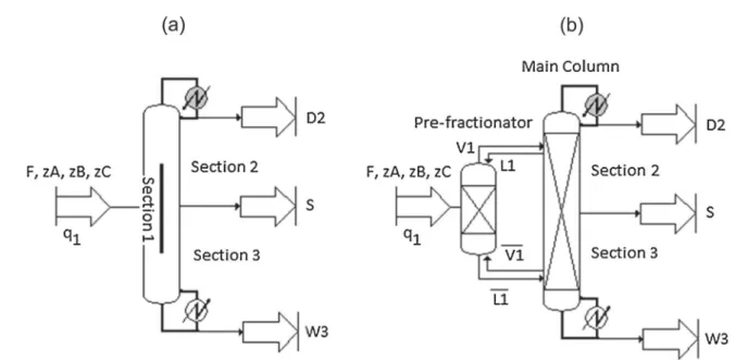
Based on the assumption (4), the divided wall column in
Fig.1(a)isequivalenttothefullythermallycoupleddistillationin
Fig.1(b). Therefore, the prefractionatorwillbe used insteadof section1.Themaincolumnwillbeusedinsteadofsections2and3. Theinterconnectingstreamsareaddedonandconnectedbetween theprefractionatorandthemaincolumn.
Basedonthefigureofthermallycoupleddistillation1(b),the maincolumncanberepresentedastwotraditionalcolumnsshown inFig.2 ifweassumea totalreboilerforcolumnIIand atotal condenserforcolumnIII.Theprefractionatorisalsoconsideredasa traditionalcolumnifweassumeapartialcondenserandapartial reboilerwhiletheinterconnectingstreamsareconsideredasthe feedflow-ratesforcolumnIIandIIIwithsuperheatedvaporand sub-cooledliquidconditions,respectively.
BasedonFig.2,componentsAandCarekeycomponentsand the component B is the distributed component in column I. Therefore,thetopofthecolumnIismainlycomponentA,apartof component Band a little of component C. The bottom of the columnIismainlycomponentC,apartofcomponentBandalittle of component A. Column II separates components A and B. Therefore,AandBarekeycomponentsandcomponentCisheavy nonkeycomponent.Basedontheassumption(7),allofcomponent C leaves from the bottom of column II. Column III separates componentsBandC.Therefore,BandCarekeycomponentsand component A is a light non key component. Based on the assumption(7),allofcomponentAleavesfromthetopofcolumn III.
The FUGK equations of material balance, minimum vapor flowrateofeachcolumn(Fig.2), andnumberofstagesforeach sectionaregiveninAppendix1.
ThisshortcutprocedureisimplementedinProSimPlussoftware toobtainallparametersofdividedwallcolumn.
2.2.SimulationwithProSimPlussoftware
Thereisnostandardmodelforthesimulationofadividedwall columnincommercialsoftware.AsshowninFig.3,therearefour possiblemodelsforthesimulation:pumparoundsequence,two— column sequence with prefractionator, two—column sequence withpostfractionator,andfour—columnsequences.Forthepump aroundsequence,Beckeretal.[3]reportedthatthemodelcanlead to convergenceproblems becausein two pointsof the column entirevaporandliquidaredrawnoff,andnoneremainsto“flow”to thenexttray.Thefour-columnsequencemodelreflectstheactual
bestsituation,butitismostdifficulttoinitialize,becauseinitial valuesofmoreinterconnectingstreamsarerequired.Itisalsothe slowestmodeltoconverge.Itisconsideredforusewithdynamic simulations[8].
Thestructuralandoperationalparametersaredeterminedby shortcut method, they are used as initial parameters for the simulation.Besidestheabovenecessaryinformation,itisnoted thatthecomposition,temperature,andflowratesof interconnect-ingstreams(2and3)or(4and5)mustbesetinthemodel.Ifthere isnospecification,thesimulationcannotberun.Notonlybecause thestream1isthefeedstreambutalsobecausestreams4and5are thefeedstreamsfortheprefractionator.Therefore,theymustbe specifiedfortheinitialrunofthesimulation.
Fig.2. Simplifiedmodeldesignofdividedwallcolumn.
Fig.3.Modelsforsimulation:(a)pumparoundsequence(b)two—columnsequencewithprefractionator(c)two—columnsequencewithpostfractionator(d)four—column sequences.
Basedonthesereasons,thetwo—columnsequencewithprefractionatorisusedtosimulatethesysteminProSimPlus.AsshowninFig.4,thefirstcolumnisconsideredasthe prefractionatorandthesecondcolumnasthemaincolumn.Theinterconnectingstreams2,3,4,and5connectthetwocolumns.Thetop,sideandbottomproductarethe streams6,7,and8,respectivelyandthefeedflowrateisstream1
3. Pilotplant
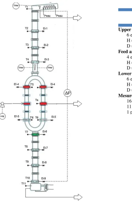
Apilotplantfor thedividedwall columnwas setupin our laboratory(LGC,Toulouse,France,2013).Fig.5showsthediagram ofthe pilotplantforseparation of a multi-componentmixture separation.Totalheightofthepilotplantis5.53m.Itismadeof glass and operates under atmospheric pressure. The column is dividedintothreeparts.Theupperandlowerpartsofthecolumn have6elementseachwithaheightof0.3mandaninnerdiameter of80mm.Themiddlepartofthecolumnisdividedintothefeed sectionandthesidesection.Eachsectionhas4elementswiththe heightofeachelementbeing0.2mandhavinganinnerdiameterof 50mm.Theheightoftheconnectingelementsbetweentheupper partand thelowerpartwiththemiddlepartareY-shapedand approximately 280mm in length. The height of the splitting elementis170mm.Thestructuredpackingusedinthepilotplant isSulzerDXfortheseparationsection.Ourpilotplanthasaparallel structureinthemiddlesection.Thiswaschosenduetothesmall inner diameter. If we put a dividing wall inside, the liquid distributionwillbeeffected.Moreover,theheattransferacrossthe dividingwall is notconsidered in thestudy. At thetop of the column, the condenser is installed and operated with cooling water.Thecondensatereturnstothecolumnduetogravityanda partistakenoutasthedistillateproductthoughttheliquidreflux splitvalve.Thetopproductisdrawnoffintoadistillatetank.Atthe bottomofthecolumn,themixtureinthereboilerisheatedbya vaporstream.Afractionistakenoutasthebottomproduct.The sideproduct,locatedatthesidesection,iscooledbycoolingwater andisdrawnoffintothesidetankbygravity.Thefeedstream,from afeedtankthroughthepump,washeatedbyapreheaterandfed intothefeedlocationinthefeedsection.Thefeedflowrateisvaried from5to7kgh"1.Toreducetheheatlossesthroughthewallofthe column,ajacketisinstalledalongtheentirelengthofthecolumn. Theliquidsplitterdefinestheliquidloadbetweenthefeedsection andthesidesection.Theliquidfromthetopofthecolumnisdrawn offvia afunnelwhich is placed inthesplittingelementand is movedbytwoelectromagnetstofacilitatetheliquiddistributionto each side of the section. The vapor is not controlled but is dependentontheinnerdiameterofthefeedandsidesectionsand thepressuredropinsidethepackedsection.Inourpilotplant,the inner diameters of the feed and side section are the same. Moreovertheheightofthepackingofeachsectionisalsothesame. Therefore,theoretically,thevaporsplitisaround0.5.
Concerningsamplesand measurements, theliquidinlet and outletstreamsin thepilotplantaremeasuredbyweighingthe quantityofliquidcollectedintheproducttanksorlostinthefeed
tank.Theinformationisnotedevery30minduringthesteadystate experimentalruns.Theaccuracyofaweighingmachineis0.001g. Thepilotplantisequippedwiththesixteentemperaturesensors (T)alongthecolumn,ofwhich,twotemperaturesensorsmeasure thetemperatureofcoolingwaterinandoutasshowninthe flow-sheetinFig.5.Alltemperaturesareautomaticallyrecorded.The liquidsamples(El)aretakenfromthefeedstream,threeproducts and11pointsalongthecolumn.Theyareanalyzedbyusinggas chromatography.Twopressuresensorsrecordthepressuredrop betweenthetopandthebottomofthecolumnduringpilotplant operation. The heat duty of the system was calculated by measuringthequantityof liquidleavingascondensatefromthe bottomofthecolumn.
HETP experiments need tobe performed to calculate HETP (heightequivalenttoatheoreticalplant)valueofthepackingused inthepilotplant.Thestandardsfortheexperimentalmethodof separating a binary mixtureat total reflux that are defined by FractionationResearchInc.(FRI)andSeparationResearchProgram (SPR) will be applied. A standard cyclohexane and n-heptane mixture is carried out in the divided wall column system at atmospheric pressure with different runs. Firstly, the flooding pointwasdetermined,thenbackingofftoroughly20%oftheflood flowrate to unloadthe bed. Secondly, the tests are run at the targetedreboilerduty.Theliquidsamplesweretakenonlyfrom El-7,El-8,andEl-9withtheheightofeachunitat0.6masshownin
Fig.5.Itis notnecessarytoanalysemoreliquidsamplesasthe samplecompositionhasstabilised.Thesamplesareanalyzedbya refractometrymethodintherefractometertoassessthe composi-tion of the samples. The number of equilibrium stages is determinedbyusingtheFenskeequation.Theresultsshowthat theaverageF-factorisequal2.01andthenumberoftheoretical stages betweenEl-7 andEl-8 orEl-8and El-9is 5.21.Thus the averageHETPwas0.115
4. Results
4.1.Designandsimulation 4.1.1.Threecomponentmixture
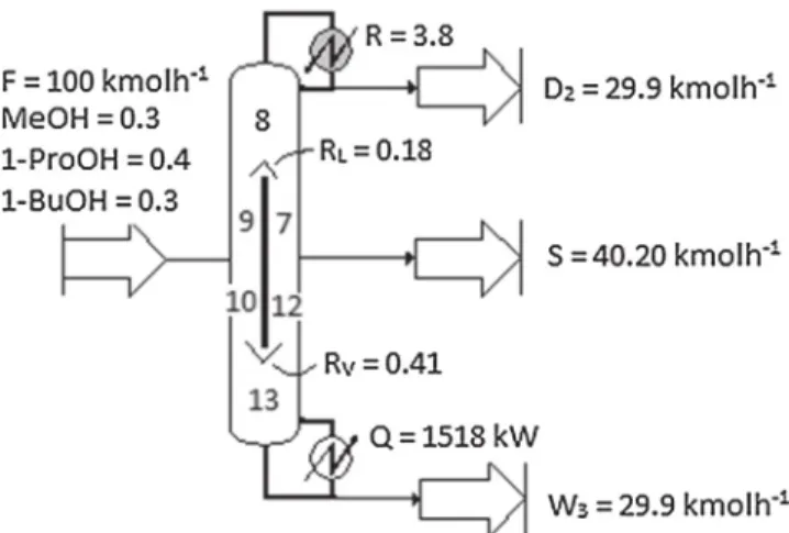
Theseparationofaternarymixture,methanol,1-propanol,and 1-butanol,iscarriedoutindividedwallcolumn.Thefeedflowrate is 100kmolh"1 and contains 30% mole fractionmethanol, 40% molefraction1-propanol,and30%molefraction1-butanol.The feed quality q1 is equal to 1. Operating pressure is 1atm.The specifications forthe productpurities for distillate and bottom productsare99%molefractionandthesideproductis98%mole
fraction. Firstly, the shortcut design procedure determines the structuralandoperationalparametersofthedividedwallcolumn. Then, steady-statesimulationswerecarried outinProSimPlus1 software.Forthethermodynamicmodel,NRTLmodelshouldbe used. Fig. 6 provides the results of design parameters for the divided wall column, while Table 3 shows the relative error betweenthespecifiedproductpuritiesandsimulationresultsof thekeycomponents.Noticethatinordertorunsimulationwith ProSimPlus1,theinformationrequiredtoinitializeasimulationis given in Fig. 6. Based on the volatilities of the components, methanolisthelightestcomponentandiscollectedasdistillate product,1-propanolisthedistributedcomponentcollectedinthe sidestream,and1-butanolistheheaviestcomponentcollectedas thebottomproduct.
InFig.6,thestructureofthedividedwallcolumnconsistedof 40-stages,with19-stagesintheprefractionatorlocatedbetween stages8and27,thefeedlocationisatstage17,thesidestreamat stage15,aliquidandvaporsplitof0.18and0.41,respectively,the refluxratioof3.8andareboilerdutyof1518kW.
Table3comparesthespecificationofkeyproductpuritieswith
simulatedresults. Theresultindicates thattheapproach works wellandprovidesboththebasisforpreliminaryoptimizationanda goodinitializationforsimulation.
4.1.2.Fourcomponentmixture
Whenthree-componentmixtureA,B,andCareseparatedinthe dividedwallcolumn,thelightestcomponentAiscollectedinthe distillateproduct,themiddlecomponentBiscollectedintheside stream,andtheheaviestcomponentCiscollectedinthebottom product. Therefore, three purecomponents can beobtained in threeproductstreams.However,iftheseparationofamixturehas more than three componentsin the divided wall column, it is difficulttoobtaineachpurecomponent.Thissectiondevelopsthe procedureforfourcomponentmixtures.Theseparationofa four-componentmixturecomposedofmethanol(A)40%molefraction, isopropanol (B) 30% mole fraction, 1-propanol (C) 20% mole fraction,and1-butanol(D)10%molefractionisconsidered.Feed flowrateis100kmol/h,feedqualityis1,andoperatingpressureis
1atm. The desired side product is isopropanol. Therefore, the distillateproductcontainsmethanolandalittleisopropanol,and thebottomproductcontainsalittleisopropanol,1-propanol,and 1-butanol.
Inthecaseofthefour-componentmixture,fromthebalance equations, there are seven equations with fifteen unknown variables.Therefore, tosolve thebalanceequations,8 variables havetobespecified:
xA;D2;xC;D2;xD;D2;xB;S;xA;S=xC;S;xD;S;xA;W3;xB;W3 as shown in Fig.7.
Inthetopproduct,xA;D2shouldbespecifiedbecauseitisakey
componentwhilexC;D2 and xD;D2aresettozerobecausewehave
madetheassumptionthatheaviercomponentsarenotpresentin thetopproduct.Inthesideproduct,xB;Sisthekeycomponentsoit
isspecified.ThecompositionofcomponentAandCalsoshouldbe known.ThereforexA,SorxC,SorxA,S/xX,Sshouldbespecified.Finally, inthebottomproduct,thelightestcomponentA(xA,W3)isfixedas zeroandthecompositionB(xB,W3)isspecified.
Inthiscase,themethanolisspecifiedat95%moleinthetop product,isopropanolisspecifiedat90%moleinthesidestream andisopropanolisspecifiedat1%moleinsteadof1-propanolor 1-butanol in the bottom product as shown in Fig. 8. Firstly, the shortcutdesignproceduredeterminesthestructuraland opera-tionalparametersofthedividedwallcolumn.Then,thesimulation ofthedividedwallcolumniscarriedoutinProSimsoftware.The resultsofstructuralandoperationalparametersfromtheshortcut methodareshowninFig.8andrelativeerrorsofkeycomponents intheproductstreamsareshowninTable4.Theresultsshowthat thedividedwallcolumnhas43 stagesinwhich thenumberof stagesintheprefractionatoris20stages.Feedandsidepositions arelocatedatstage14.Theliquidandvaporsplitsare0.5and0.69, respectively. The reflux ratio is 2.85 and the reboiler duty of 1268kW.
Table4showsthatallrelativeerrorsarenegativesthatmeans
thatthesimulatedresultsdo notreachtothespecification.All relativeerrorsarelessthan"5%.
4.2.Experimentalvalidation 4.2.1.Componentsystem
Theprocedurefordesigningadividedwallcolumnappliesnot onlyforternarymixturesbutalsoforfourcomponentmixtures. Therefore, toverify the procedure, ternary mixtures and four-componentmixturesareinvestigatedinthepilotplant.Inthefirst case,aternarymixtureofmethanol,1-propanoland1-butanolare chosenforinvestigationinourpilotplant.Thismixturewaschosen becausethemaximumboilingpointofthemixtureis118*Cwhile
thepreheaterofthepilotplantcanheatthemixtureupto150*C.
Moreover, the alcohols can be easily bought in the chemical industry.Accordingtotheirboilingpointsfromlowesttohighest, methanolisobtainedinthetopproduct,1-propanolisobtainedas thesideproduct,and1-butanolisobtainedasthebottomproduct. Thedifferentfeedcompositionsofthemixtureanddifferentliquid splitswillbeconsidered.Inthesecondcase,thefour-component mixtureofthemethanol,isopropanol,1-propanol,and1-butanol alsoiscarriedoutinthedividedwallcolumn.Thedistributionof thecomponentstotheproductsisstudied.Firstly,isopropanolisa distributedcomponent.Therefore,methanolisobtainedasthetop product, isopropanol is obtained as the side product, and 1-propanol and 1-butanol are obtained as the bottom product. Secondly, 1-propanol is a distributed component. Therefore, methanol and isopropanol are obtainedas the top product, 1-propanolisobtainedasthesideproduct,and1-butanolisobtained asthebottomproduct.
4.2.2.Ternarymixture
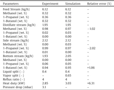
First,aternarymixtureofmethanol,1-propanol,and1-butanol iscarriedoutinthepilotplant.Table4displaysthecomparison between experimental operating parameters at steady state conditionandsimulatedresults.Feedflowrate,feedcomposition, distillateflowrate,sideflowrate,reflux ratio,andliquidsplitsin simulationaresetthesameasexperimentaldatawhilevaporsplit are adjusted in order to obtain the best fitting between experimental dataandsimulated results.The resultshowsthat relativeerrorsofkeycomponentofthreeproductsarelessthan5%.
Table3
Relativeerrorsbetweenspecifyproductpurityandsimulateresultofkeycomponent.
Keycomponent Specificationofkeycomponent(molefraction) Simulation(molefraction) Relativeerror(%)
Methanol 0.99 0.99 0.00
1-Propanol 0.98 0.97 "1.02
1-Butanol 0.99 0.97 "1.02
Inthesimulation,weassumethattheheatlossesfromthecolumn wallsarenegligible.Thus,heatdutyofcondenserinexperimentis usedtocomparewithheatdutyofreboilerinsimulationinsteadof heatdutyofreboilerasshowninTable5.Therelativeerrorisequal to6.31%.
Fig.9showsthecompositionandtemperatureprofilesalong thecolumn.Thisfigureindicatesthattheproductpuritiesshow verygoodagreementbetweenexperimentandsimulationnotonly forproductsbutalsoforcompositioninwholecolumn.Theresults canindicatetworegions:Methanoland1-propanolareseparated intheupperpartwheremolefractionof1-butanolisalmostzero fromapackingheightof2.6–4.4m.The1-propanoland1-butanol are separatedinthelowerpartwheremethanol isalmostzero
Fig.7.Specifiedvariablesforfour-componentmixtureindividedwallcolumn.
Fig.8.Designparametersforthedividedwallcolumn.
Table4
Relativeerrorsbetweenspecifiedproductpurityandsimulationofkeycomponents. Keycomponent Specificationofproducts Simulation Relativeerror(%) Methanol 0.95 0.918 "3.36 Isopropanol 0.90 0.860 "4.44 Isopropanol 0.01 0.0096 "4.00
Table5
Operationparametersandresultsforexperimentalsteady-stateruns. Parameters Experiment Simulation Relativeerror(%) FeedStream(kg/h) 6.12 6.12 – Methanol(wt.%) 0.32 0.32 – 1-Propanol(wt.%) 0.36 0.36 – 1-Butanol(wt.%) 0.32 0.32 – Distillatestream(kg/h) 1.95 1.95 – Methanol(wt.%) 0.98 0.97 "1.02 1-Propanol(wt.%) 0.02 0.03 – 1-Butanol(wt.%) 0.00 0.00 – Sidestream(kg/h) 2.12 2.12 – Methanol(wt.%) 0.00 0.03 – 1-Propanol(wt.%) 0.99 0.97 "2.02 1-Butanol(wt.%) 0.01 0.00 – Bottomstream(kg/h) 1.93 2.05 – Methanol(wt.%) 0.00 0.00 – 1-Propanol(wt.%) 0.06 0.05 – 1-Butanol(wt.%) 0.94 0.95 +1.06 Liquidsplit(") 0.4 0.4 – Vaporsplit(") – 0.65 – Refluxratio(") 4 4 – Heatduty(kW) 2.85 3.03 +6.31 Pressuredrop(mbar) 3.1 – –
from0to2.2m.Clearlytheupperpartisusedtoseparatemethanol and1-propanolandthelowerpartisusedtoseparate1-propanol and1-butanol.Inthemiddlepart,1-propanolreachesamaximum thusitiscollectedasthesideproduct.Fig.9alsoshowsthatthe content of methanol increases and the content of 1-propanol decreases significantly from 3.8 to 4.4m and the content of 1-propanoldecreasesand1-butanolincreasesnotablyat0–0.6m. Inall,foursteady-stateexperimentalrunsarereachedofthe ternary mixture methanol, 1-propanol, and 1-butanol with differentfeedcompositions, feedflowrates, refluxratios, liquid splits,andreboilerheatduty.Thefeedstreamscanbeclassifiedas follows:Case1hasthesamemassfractionof1-propanoland 1-butanolandahighermassfractionofmethanol;Case2hasthe samemassfractionofmethanoland1-butanolandahighermass fractionof1-propanol;Case3isrepresentedbeforewitha feed mixturewithalmostequalmassfractionofallcomponents;Case 4hasthesamemassfractionofmethanoland1-propanolanda highermassfractionof1-butanol.Cases1and2haveliquidsplit equalto0.5,however,Cases3and4haveliquidsplitof0.4and0.6, respectively.Refluxratiosaredeterminedfromsimulationresults andsetintotheactualexperiments.The pressuredropof each experimentwaschangedfrom2.8to6.6mbarwhiletheheatduty changedfrom4.3kWto5.4kW.Forallexperiments,theproduct purities show very good agreement between experiment and simulation along the column and at the top and the bottom column,withamaximumdeviationof3%.Allresultsaregivenin
Appendix1.
4.2.3.Fourcomponentmixture
Theseparationofafour-componentmixtureinapilotdivided wall column is also investigated. Normally, the divided wall columnwithasingledividingwallcanseparateathreecomponent mixtureintothreehighpurityproducts.However,theseparation ofamixtureoffourormorecomponentscarriedoutinadivided wallcolumnachievesonlytwohighpurityproductsandonemixed product. Therefore this section investigates the distribution of components in the divided wall column to see if the fourth
componenthasaneffectonthepurityoftheproducts.Twocases arestudied.First,thefeedstreamofthefifthcasecontains8%mass fraction methanol, 16% mass fraction isopropanol, 45% mass fraction1-propanol,and31%massfraction1-butanol.Thismixture ispreparedbecausewewouldliketocollect1-propanolastheside product.Therefore,methanolandisopropanolarecollectedinthe topproductand1-butanoliscollectedinthebottomproduct.In thesecondcase,thedesiredsideproductisisopropanol.Therefore, the feed stream of the mixture contains 29% mass fraction methanol,35% mass fractionisopropanol, 22% massfraction 1-propanol,and14%massfraction1-butanol.Thefeedflowrateofthe studiedcasesarearound6kg/h.Theliquidsplitandrefluxratioare 0.5 and 6, respectively. Fig.10 illustratesthe temperature and compositionprofilescomparisonbetweentheexperimentaldata andsimulatedresults
Inthefirststudiedcase(Fig.10(a)),amixtureofmethanoland isopropanolwasobtainedasthetopproduct;1-propanolasthe sideproductwith0.97massfraction;and1-butanolasthebottom product with 0.92 mass fraction. In the second studied case (Fig.10(a’)),methanolisthetopproductwith72%massfraction; isopropanolis thesideproduct with0.967mass fractionand a mixtureof1-propanoland1-butanolisthebottomproduct.The resultsindicatedthatahighpurityofkeycomponentsintheside product is obtained. The maximum relative error between experimentandsimulation ofthekeycomponentobtainedwas lessthan10%.Thusitispossibletonotethatthesimulationresults andexperimentaldataareingoodagreement.Thevaporsplitsof allthestudiedcasesarelessthan0.5asperthetrenddiscussedin section4.11whentheliquidsplitis0.5.ThevaporsplitofCases 5and6are0.46and0.45,respectively.
5. Sensitivityanalysisofdividedwallcolumn
Inthispaper,adesignparameterofthedividedwallcolumnis determined by our approach. Then, in order to determine the sensisitiveparametersofdividedwallcolumns,theeffectsofthe structural parameters of the divided wall column such as the
heightofthewall,theverticalpositionofthewallandnumberof stagesofeachsectionareanalyzed.Moreover,thisstudywillalso help to analyze the effectiveness of the short cut method to determinethe structuralparametersminimizing energetic con-sumptionofDWCcolumns.
Notice that the purity specifications of key components of product streams have to be obtained in all cases. The ternary mixture consisting of benzene 0.33mole fraction, toluene 0.33molefractionand o-xylene0.34molefractionischosen for investigation.
5.1.Effectoftheverticalpositionandheightofthewall
The purposeof thissectionis toinvestigate howtheenergy consumptionchangeswhentheverticalpositionandheightofthe
wallchange.Firstly,theverticalpositionof thewall (Fig.11)is moved(N3andN6change)fromthebottomtothetopalongthe column while the height of the wall is constant at 15 stages (N1+N2=N4+N5).Thetotalnumberofstageshavenotchanged (N3+N4+N5+N6), and the feed (N1) and side stream (N4) locationsarethesameastheshortcutresults.Thepositionofthe dividingwallismarkedaszeroinFig.12andisthesameposition thatcomesfromshortcutresults.
Itislocatedbetweenstages9(N3)and24(N3+N4+N5).Inthe negativerange,theverticalpositionofthedividingwallislower thanthe initialposition,and in thepositive range,thevertical positionofthedividingwallishigherthantheinitialposition.Asin
Fig.12,theheatdutyofthedividedwallcolumnisloweratthe initialpositionQb=1245kW.Thelowerorhigherthepositionof thewall,thedividedwallcolumnhasahigherenergydemand.The
Fig.11.DWCdesignparameters.
Fig.12.Effectoftheheightandverticalpositionofthewallontheheatdutyofreboiler.
reboilerheatduty is2400kWwhentheverticalpositionofthe dividingwallis3stageslower.Itislocatedbetweenstages12and 27. The heatduty of thereboileris 1850kWwhen thevertical positionofthedividingwallis3stageshigher.Itislocatedbetween stages6and21.Theresultshowsthattheverticalpositionofthe dividingwallfromtheshortcutresultsrequireslessenergywhen thestructurechanges.
Secondly,thereboilerheatdutyisalsoanalyzedwithachange oftheheightofthedividingwall(N1+N2=N4+N5change).The heightofthewallis15stages,aspertheshortcutresult,marked
zeroinFig.12.Inthenegativerange,thenumberofstagesofthe dividingwallisdecreasedwhileinthepositiverange,thenumber ofstagesofthedividingwallisincreased.Thefeed(N1)andside product(N4)positionremainsthesameastheinitialparameters.
Fig.12 showsthat theenergyconsumption of thedividedwall column is lower if the number of stage decreases from 15 to 13stages.Thereboilerheatdutyisaround1245kW.Thereboiler heatdutyincreasedto2300kWwhentheheightofthedividing walldecreasesto9stages.Thereboilerheatdutyalsoincreasedto 1800kW when the height of the dividing wall increases to 21stages.Clearly,ourprocedurefordesignofdividedwallcolumns givesgoodstructuralparameters;theresultsareveryclosedtothe minimumenergydemandofthecolumn.
5.2.Effectofthenumberofstages
Inthissection,thechangeofthereboilerheatdutyisstudied whenthenumberofstagesofonesectionhaschangedwhilethose ofothersectionsarefixedthesameasinitialparameters.Fig.13
showsthattheheatdutyofthereboilerchangeswiththenumber
Table6
ThreeternarymixtureswithdifferentESIvalue.
Mixture ComponentsA,B,C ESI Pressure(atm) M1 n-Pentane/n-hexane/n-heptane 1.04 2
M2 n-Butane/i-pentane/n-pentane 1.86 4.7 M3 i-Pentane/n-pentane/n-hexane 0.47 2
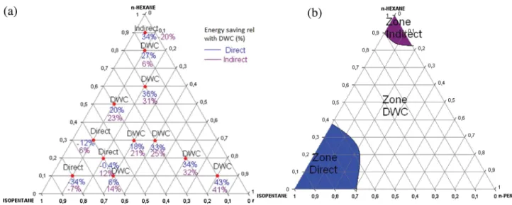
Fig.14.Energysaving(a)andoptimalregions(b)onthecompositionspaceforM1.
ofstagesofeachsection.Theinitialparametersfromtheshortcut resultsaremarkedzeroasshowninFig.13includingN1—8stages, N2—9 stages, N3—9 stages, N4—8 stages,N5—7 stages, andN6— 7stages.Inthenegativerange,thenumberofstagesdecreasesand inthepositiverange,thenumberofstagesincreases.
Fig.13showsthattheheatdutyofthereboilerincreaseswhen the number of stages of each section decreases. Theoretically, when the numbers of stages decreases, in order to retain the specifiedproductpurity,therefluxratiohastoincrease.Therefore thereboilerheat duty willincrease. In Fig.13,thenumbers of stagesinthesection1,4,and6hasasignificanteffectontheheat dutyofthereboilerwhilethenumberofstagesinsections2and 3arenotsignificantlyaffected.Thenumberofstagesinsections 1and5cannotdecreasemoreasthepurityspecificationcannotbe reached, regardless of theenergy supplied tothe column. The numberof stages in each sectionincreases,the energyduty of reboiler slightly decreases as shown in Fig. 13. Clearly, it is importanttonoticethatwhenthenumberofstagesincreases,the capitalcostoftheprocesswillalsoincrease.So,ourprocedurefor designofdividedwallcolumnsgivesgoodinitialvalueofnumber ofstageregardingtotheminimumenergydemandofthecolumn. 5.3.Energyconsumptioncomparisonbetweentraditionalsequences andDWCsystem
Theideaistobuildaternarydiagramandfindtheboundary wheretheconfigurationofdistillationisthemosteconomical.In ordertodo this,theenergy usedfor thetraditionaldistillation columnanddividedwallcolumnforthreeternarymixturesM1, M2andM3areconsidered.Table6displaysthedifferentvaluesof theeaseofseparationindex(ESI)ofthemixture.ESIisdefinedby TedderandRudd[17]:thevalueESIequal(orlessthan,ormore than)to1thatmeansthesplitA/Bisasdifficultas(ormorethan,or lessthan)thesplitB/C.
ESI¼KAKC K2B
whereKA;KB;KCarevolatilitiesofcomponentA,B,andC.
Thefeedflowrateis100kmolh"1.Theoperatingpressurefor eachmixtureischosentoensuretheuseofcoolingwaterinthe
condensers.Thelightestcomponentisrecoveredatthetopofthe columnat99%,theheaviestcomponentisrecoveredatthebottom ofthecolumnat99%andtheintermediatecomponentisrecovered in the middle of the column at 95%. A wide range of feed compositionisstudied.
Figs.14(a),15(a),and16(a)showtheenergysavingrelatedto thedividedwallcolumnwhileFigs.14(b),15(b),and16(b)show thedistillationzonesofthemixtureM1,M2,andM3.Thereddots arethedifferentfeedcompositions;thebluenumbersandpurple numbersarethepercentageofenergysavingrelativetoDWC,for directandindirectsequence(anegativevaluemeansanenergy gainrelativetothecolumnDWC).
The results show that the energy saving of DWC system dependsontheamountofintermediatecomponentinthefeed. MoreenergysavingconsumptioninDWCsystemcanbeachieved ifthemixturehasmoremiddlecomponentinthefeed composi-tion.Forexample,inthemixtureM1,theenergysavingincreases from 18% to 44% when the middle component (n-Hexane) increasesfrom20%molefractionto80%molefractioninthefeed composition.Kissetal.[12]whichshowaproceduretomakethe right choice between process heat integration or traditional arrangementsbasedonthedifferenceinboilingpointsbetween the top and bottom product (
D
Tb), feed flowrate of eachcomponent(FD—productflowrateatthetopofthecolumn,FS— product flowrate of the side product of thecolumn, and FW— productflowrateatthebottomofthecolumn),andproductpurity (xD,xS,andxW)concludethesametendency.
Theresultsshowthatthedistillationzonesdependsalsoofthe ESIvalue.Thedistillationzoneforindirectsequenceisevenlarger thantheESIvalueishigh.Indeed,ESIvalueof1.86showthelargest zoneforindirectsequencezone(Fig.15b).Butthereisadifferent trend for the direct sequence zone. More mixtures should be simulatedtoconcludewithESIvalue.Theaverageenergysaving forthedifferentvaluesofESIis19%,21%and24%formixtureM1, M2,andM3respectively.
Based on the discussion, the divided wall column can save energydutycomparedwiththetraditionalsequence.However,the selectionofthebestarrangementisbasedonthefeedcomposition and ESI value of the mixture. A representation with a ternary diagramcanbeusefultoselectthemosteconomicalconfiguration.
6. Conclusion
ThepaperhasgivenaprocedurefordesignofDWCsystemin whichbothstructuralandoperationalparametersofDWCsystem arerapidlydetermined.Basedonthesimulatedresults,itcanbe concluded that ourprocedurecan give a goodinitialization for rigoroussimulation.Theimplementation,startupandoperationof apilotplanttocarryoutalcoholmixtureareachievedinthepaper. Itindicatedthatthesimulatedresultsareingoodagreementwith the experimental data at steady state condition and then, the proposedprocedureappearstobewelladaptedtoquicklydesign dividedwallcolumns.
Theenergyconsumptionofthetraditionalarrangementsand DWC system are compared. The separations of three different ternary mixtures with different values of ESI are studied. The energyconsumptionoftheDWCsystemismorefavorablethanthe traditionalarrangementsifthemixturehasmoremiddle compo-nent. Clearly,theDWCsystemis notalwaysthebestcompared withtheconventionalarrangements.Theselectiondependsonthe feedcompositionandtheESIvalueofthemixture.
Acknowledgement
TheauthorsgratefullyacknowledgeProSim1Companyfortheir supportanddiscussions.
Appendix1.
FUGKequationforshortcutmethodofDWCcolumnsystem Materialbalanceofdividedwallcolumnforternarymixture
BasedonFig.2,materialbalanceequationsforeachcomponent ForthecomponentA
FzA¼D2xA;D2þSxA;SþW3xA;W3
ForthecomponentB
FzB¼D2xB;D2þSxB;SþW3xB;W3
ForthecomponentC
FzC¼D2xC;D2þSxC;SþW3xC;W3
and
xA;D2þxB;D2þxC;D2¼1
xA;SþxB;SþxC;S¼1
xA;W3þxB;W3þxC;W3¼1
We knowthe feedflowrate(F)and feedcompositionðzA;zB;zCÞ.
From theaboveequations,there aretwelve unknown variables while there are six equations. Therefore, in order to solve the equations,sixofunknownvariablesmustbespecified.Unknown variablesandspecificationarelistedinTable2.
We assumed that the component C goes completely tothe bottomofthecolumnIIandthecomponentAgoescompletelyto the top of the column III. Therefore, we have xC;D2¼0 and
xA;W3¼0.
MinimumvaporflowrateofDWCsystem MinimumvaporflowrateofcolumnI
InthecolumnI,therecoveryratioofcomponentiinthetop productdefinedas:
t
i;T¼xi;D1D1
Fzi
RecoveryratioofcomponentsAandCshouldbechosenbetween: 1>
t
A;T>1" xA;SS zAF 0<t
C;T< xC;SS zBFTherecovery ratioofcomponent Bis calculatedbyStichlmair’s equation[16].Itiscalledthepreferredsplit
b
p:t
B;T¼b
p¼"a
AzAF=a
A"u
1 ð Þ"ða
AzAF=a
A"u
2Þa
BzBF=a
B"u
1 ð Þ"ða
BzBF=a
B"u
2Þ whereu
1;u
2—aretworootsofUnderwood’sequationattheminimumreflux condition. They must be following ranges:
a
A>u
1>a
B>u
2>a
C 1" q1 ð Þ¼X C i¼Aa
izia
i"u
whereq1—Feedqualityisthefractionofthefeedthatisliquidforthe columnI.
Theminimumvaporflowintheprefractionatorisdetermined byUnderwood’sequation: V1;min¼X C i¼A
a
ixi;D1D1a
i"u
andwechoose:V1;min¼max$V1;minð
u
1Þ;V1;minðu
2Þ%MinimumvaporflowrateofcolumnII
Theinterconnectingstreams,asaturatedvaporstreamðV1Þis
leftfromthecolumnIandasaturatedliquidstreamðL1Þisreturned
intothecolumnI,canbemodifiedbyequivalentfeedstreamwitha superheatedvaporcondition.Therefore,thequalityofthefeedfor thecolumnII:
q2¼L2"L2 D1 ¼"
V1;min"D1
D1
Attheminimumrefluxcondition, theUnderwood’sequation canbewrittenasfollows:
1" q2 ð Þ¼X C i¼A
a
ixi;D1a
i"u
0 whereu
01;u
02aretworootsofUnderwood’sequationattheminimum refluxcondition.Theymustbefollowingranges:a
A>u
0
1>
a
B>u
02>a
CTheminimumvaporflowinthecolumnIIcanbeestimatedby:
V2;min¼
XC
i¼A
a
ixi;D2D2Therefore,wecanchoose V2;min¼max V2;minð
u
01Þ;V2;minðu
02Þ$ %
MinimumvaporflowrateofcolumnIII
The streamis fed tothe column III that is connected from interconnectingstreamsareasaturatedliquidstream L1Þ
&
anda saturatedvaporstreamV1Þ
&
,canbemodifiedbyequivalentfeed streamwithasub-cooledliquidcondition.Thequalityofthefeed forthecolumnIIIcanbecalculatedby:
q3¼L3"L3 W1 ¼
V1;min"D1þq1F
W1
Attheminimumrefluxcondition,theUnderwood’sequation canbewrittenasfollows:
1" q3 ð Þ ¼X C i¼A
a
ixi;W1a
i"u
} whereu
} 1;u
}2aretworootsofUnderwood’sequationattheminimum
refluxcondition.Theymustbefollowingranges:
a
A>u
} 1>a
B>u
}2>a
CTheminimumvaporflowinthecolumnIIIcanbedetermined by: V3;min¼" XC i¼A
a
ixi;W3W3a
i"u
} Therefore,wechooseV3;min¼max V3;minð
u
}1Þ;V3;minðu
}2Þg$
MinimumvaporflowrateofDWCsystem
TheminimumvaporflowrateofDWCsystemshouldbechosen byHalvorsenandSkogestad[7,10]
Vmin;DWCs¼max V2;min;V3;minþð1" q1ÞF
$ %
NumberofstagesforeachsectionofDWCsystem
TheminimumrefluxratiooftheDWCsystemcanbecalculated asfollows:
Rmin¼
Vmin;DWCs
D2 "
1
TheoperatingrefluxratiooftheDWCsystemcanbechosenas: R¼ 1;2
1;5 " #
Rmin
Theliquidandvaporsplitsbetweenprefractionatorandmain columncanbedefinedas:
RL¼ L1 L2 RV¼ V1 V3
StartingfromthestructureasshowninFig.2,anevaluationofNET foreachsectionandrefluxratioforeachcolumnarecomputed basedontraditionalshortcutmethodofFenske,Underwood,and Gilliland and Kirkbride equations by Kister [9]. The minimum number of stages can be determined by Fenske equation for
columni:
Ni;min¼
lnðSÞ lnð
a
avÞwhereSisgivenbyequation S¼ xLK xHK " # Di xHK xLK " # Wi ;i¼1 3
Then, we calculate number of stages by using Gilliland equation:
Y¼0;75:'1"X0;5668(
whereXandYaregivenbyequation X¼R"Rmin
Rþ1
Y¼N"Nmin Nþ1
FeedlocationineachcolumncanbecalculatedbyKirkbridge equation NR NS " # i ¼ zHK zLK " # i xLK;Wi xHK;Di " #2W i Di ( )0:206 Appendix2.
Experimentalresultsforternarymixture
Operatingparametersandresultsforexperimentalsteady-state runs
Parameters Case1 Case2 Case3 Case4 Feed(kg/h) 5.41 5.77 6.12 5.97 Methanol(wt.%) 0.4 0.29 0.32 0.3 1-Propanol(wt.%) 0.3 0.46 0.36 0.24 1-Butanol(wt.%) 0.3 0.25 0.32 0.46 Distillate(kg/h) 2.66 2.00 1.95 1.80 Methanol(wt.%) 0.814 0.85 0.98 0.93 1-Propanol(wt.%) 0.186 0.15 0.02 0.07 1-Butanol(wt.%) 0 0 0 0 Sidestream(kg/h) 1.038 2.17 2.12 0.918 Methanol(wt.%) 0 0 0 0 1-Propanol(wt.%) 0.995 1 0.998 0.96 1-Butanol(wt.%) 0.005 0 0.002 0.04 Bottomstream(kg/h) 1.872 1.7 1.93 3.144 Methanol(wt.%) 0 0 0 0 1-Propanol(wt.%) 0.21 0.114 0.06 0.19 1-Butanol(wt.%) 0.979 0.886 0.94 0.81 Liquidsplit(") 0.5 0.5 0.4 0.6 Refluxratio(") 3 6 4 4 Heatduty(kW) 5.17 5.1 4.3 5.4 Heatcondenser(kW) 2.67 2.2 2.24 2.5 Pressuredrop(mbar) 2.8 6.6 3.1 2.4 Relativeerror(%)of massbalances Total "2.92 "1.73 1.96 "1.80 Methanol 0.47 "1.59 2.40 7.51 1-Propanol 2.12 "0.11 "3.04 "7.12 1-Butanol "12.48 "4.88 7.15 2.81
Compositionandtemperatureprofilesofexperimentaldataand simulationresultsforternarymixtureFig.A1–A4.
0 0.5 1 1.5 2 2.5 3 3.5 4 4.5 60 80 100 120 H e ig h t o f P a ck in g ( m ) Temperature (°C) Main column PrefracConator
0 0.5 1 1.5 2 2.5 3 3.5 4 4.5 -0.2 0 0.2 0.4 0.6 0.8 1 1.2 H e ig h t o f P a ck in g ( m ) FracCon mole MeOH ProOH BuOH
Fig.A2.Case2.
0 0.5 1 1.5 2 2.5 3 3.5 4 4.5 65 85 105 125 H e ig h t o f P a ck in g ( m ) Temperature (°C) Main column PrefracConator
0 0.5 1 1.5 2 2.5 3 3.5 4 4.5 -0.2 0 0.2 0.4 0.6 0.8 1 1.2 P a ck in g h e ig h ( m ) FracCon mole
Methanol 1-propanol 1-butanol
Fig.A1. Case1.
0 0.5 1 1.5 2 2.5 3 3.5 4 4.5 60 80 100 120 H e ig h t o f P a ck in g ( m ) Temperature (°C) Main column PrefracConator
0 0.5 1 1.5 2 2.5 3 3.5 4 4.5 -0.2 0 0.2 0.4 0.6 0.8 1 1.2 H ei g h t o f P a ck in g ( m ) FracCon mole MeOH ProOH BuOH
References
[1]K.A.Amminudin,R.Smith,Designandoptimizationoffullythermallycoupled distillationcolumns:part2:applicationofdividingwallcolumnsinretrofit, Chem.Eng.Res.Des.79(7)(2001)716–724.
[2]K.A.Amminudin,R.Smith,D.C.Thong,G.P.Towler,Designandoptimizationof fullythermallycoupleddistillationcolumns:Part1:Preliminarydesignand optimizationmethodology,Chem.Eng.Res.Des.79(7)(2001)701–715. [3]H.Becker,S.Godorr,H.Kreis,Partitioneddistillationcolumns—whywhenand
how,Chem.Eng.108(1)(2001)68–74.
[4]C.Triantafyllou,R.Smith,Thedesignandoptimizationoffullythermally coupleddistillationcolumns,Inst.Chem.Eng.70(March(A2))(1992)118–132. [5]C.J.Calzon-McConville,M.B.Rosales-Zamora,J.G.Segovia-Hernandez,S.
Hernandez,V.Rico-Ramírez,Designandoptimizationofthermallycoupled distillationschemesfortheseparationofmulticomponentmixtures,Ind.Eng. Chem.Res.45(2)(2006)724–732.
[6]K.T.Chu,L.Cadoret,C.C.Yu,J.D.Ward,Anewshortcutdesignmethodand economicanalysisofdividedwallcolumns,Ind.Eng.Chem.Res.50(15)(2011) 9221–9235.
[7]I.J.Halvorsen,S.Skogestad,Minimumenergyconsumptionin
multicomponentdistillation.3.Morethanthreeproductsandgeneralized Petlyukarrangements,Ind.Eng.Chem.Res.42(3)(2003)616–629. [8]HaoLing,WilliamL.Luyben,Newcontrolstructurefordividedwallcolumns,
Ind.Eng.Chem.Res.48(13)(2009)6034–6049.
[9]HenryZ.Kister,DistillationDesign,McGraw-Hill,1992. [10]I.J.Halvorsen,S.Skogestad,Minimumenergyconsumptionin
multicomponentdistillation:2.Three-productPetlyukcolumn,Ind.Eng. Chem.Res.42(2003)605–615.
[11]Y.H.Kim,Structuraldesignandoperationofafullythermallycoupled distillationcolumn,Chem.Eng.J.85(2)(2002)289–301.
[12]A.A.Kiss,S.J.FloresLandaeta,C.A.InfanteFerreira,Towardsenergyefficient distillationtechnologies—makingtherightchoice,Energy47(1)(2012)531– 542.
[13]NellyRamirez-Corona,ArturoJiménezGuiérrez,AngelCastroAgüero,Vicente Rico-Ramirez,OptimumdesignofPetlyukanddividedwalldistillation systemsusingashortcutmodel,Chem.Eng.Res.Des.88(2010)1405–1418. [14]NooriSotudeh,BahramHashemiShahraki,Amethodforthedesignofdivided
wallcolumns,Chem.Eng.Technol.30(9)(2007)1284–1291.
[15]N.Sotudeh,B.H.Shahraki,Extensionofamethodforthedesignofdividedwall columns,Chem.Eng.Technol.31(1)(2008)83–86.
[16]J.Stichlmair,Distillationandrectification,Ullmann’sEncyclopediaof IndustrialChemistryB3,(1988) 4-1-4-94.
[17]D.W.Tedder,D.F.Rudd,Parametricstudiesinindustrialdistillation:PartI. Designcomparisons,AIChEJ.24(2)(1978)303–315.
[18]D.B.VanDongen,M.F.Doherty,Designandsynthesisofhomogeneous azeotropicdistillations.1.Problemformulationforasinglecolumn,Ind.Eng. Chem.Fundam.24(4)(1985)454–463. 0 0.5 1 1.5 2 2.5 3 3.5 4 4.5 60 80 100 120 H e ig h t o f P a ck in g ( m ) Temperature (°C) Main column PrefracConator
0 0.5 1 1.5 2 2.5 3 3.5 4 4.5 -0.2 0 0.2 0.4 0.6 0.8 1 1.2 H e ig h t o f P a ck in g ( m ) FracCon mole MeOH ProOH BuOH